EP1439645A2 - WDM optische Quelle und damit ausgerüstete passive optische Netzwerkeinrichtung - Google Patents
WDM optische Quelle und damit ausgerüstete passive optische Netzwerkeinrichtung Download PDFInfo
- Publication number
- EP1439645A2 EP1439645A2 EP04000024A EP04000024A EP1439645A2 EP 1439645 A2 EP1439645 A2 EP 1439645A2 EP 04000024 A EP04000024 A EP 04000024A EP 04000024 A EP04000024 A EP 04000024A EP 1439645 A2 EP1439645 A2 EP 1439645A2
- Authority
- EP
- European Patent Office
- Prior art keywords
- optical
- signals
- wavelength
- division
- multiplexed
- Prior art date
- Legal status (The legal status is an assumption and is not a legal conclusion. Google has not performed a legal analysis and makes no representation as to the accuracy of the status listed.)
- Withdrawn
Links
Images


Classifications
-
- H—ELECTRICITY
- H04—ELECTRIC COMMUNICATION TECHNIQUE
- H04L—TRANSMISSION OF DIGITAL INFORMATION, e.g. TELEGRAPHIC COMMUNICATION
- H04L12/00—Data switching networks
- H04L12/28—Data switching networks characterised by path configuration, e.g. LAN [Local Area Networks] or WAN [Wide Area Networks]
-
- H—ELECTRICITY
- H04—ELECTRIC COMMUNICATION TECHNIQUE
- H04B—TRANSMISSION
- H04B10/00—Transmission systems employing electromagnetic waves other than radio-waves, e.g. infrared, visible or ultraviolet light, or employing corpuscular radiation, e.g. quantum communication
- H04B10/50—Transmitters
- H04B10/501—Structural aspects
- H04B10/506—Multiwavelength transmitters
Definitions
- the present invention relates to a wavelength-division-multiplexed optical source and a passive optical network system employing the same, and more particularly, to a wavelength-division-multiplexed optical source for providing data services and broadcasting services, and to a passive optical network system employing the same.
- a Wavelength-Division-Multiplexed Passive Optical Network provides broadband communication services at very high speed by using intrinsic wavelengths assigned to each subscriber. Therefore, the WDM-PON can keep a communication secret with certainty and can easily accommodate an increase in communication capacity as well as a special communication service requested by a subscriber.
- the WDM-PON can be reconfigured for new subscriber terminals just by adding intrinsic wavelengths to be assigned to each additional terminal.
- the WDM-PON can thus easily be made to accommodate extra subscriber terminals.
- a central office (CO) and subscriber terminals of which the WDM-PON is comprised must have at least one optical source with an assigned oscillation wavelength and at least one wavelength-stabilizing circuit for stabilizing the wavelength of the optical source, which imposes a high cost burden on the subscribers to the WDM-PON.
- the WDM-PON has not yet been put to practical use for this reason in spite of its many advantages. There accordingly exists a need for an economical optical source in order to put the WDM-PON to practical use.
- the broadcasting service provision method using a DFB laser directly modulates a distributed feedback laser in accordance with broadcasting service signals, amplifies the modulated signals through an optical amplifier, and outputs the amplified signals through a power splitting optical link to provide the broadcasting service to each subscriber terminal.
- the power splitting optical link is provided with a special link so as to be differentiated from the optical link of WDM for data service.
- This method complicates the manufacturing procedure and requires the use of high-priced elements which are necessary to provide accurate wavelength selectivity and wavelength stability of a WDM optical source.
- the method further requires a special power splitting optical link so as to be differentiated from the optical link of WDM for data service. Subscribers are therefore burdened by additional construction cost and continuous investment from the viewpoint of maintenance and operation.
- the broadcasting service provision method using a DFB laser array carrying some of the same disadvantages as the broadcasting service provision using a DFB laser, electrically multiplexes data service signals and broadcasting service signals of differing frequency bands, modulates directly each distributed feedback laser in accordance with the multiplexed signals, and then outputs the signals through optical link of WDM to provide the broadcasting service to each subscriber terminal. Similar to the case of the broadcasting service provision method using a DFB laser, this method complicates manufacturing and requires the use of high-priced elements which are needed to provide accurate wavelength selectivity and wavelength stability of the WDM optical source. Also characteristic of this method is degradation of data service signals and broadcasting service signals due to their simultaneous provision through one channel.
- the broadcasting service provision method using a spectrum-sliced light source modulates directly or indirectly an optical source outputting optical signals of wide bandwidth in accordance with broadcasting service signals, spectrally slices the modulated signals, and outputs plenty of wavelength-sliced channels generated as the result through optical link of the WDM to provide the broadcasting service to each subscriber terminal.
- This method therefore doesn't need an optical source with specific generation wavelength and a wavelength-stabilizing circuit for stabilizing the wavelength.
- Examples of an optical source for the spectrum-sliced method are a light emitting diode (LED), a super luminescent diode (SLD) and a fiber amplifier light source.
- transmission performance may be degraded for the broadcasting service provision method using a spectrum-sliced light source, because this method causes some distortion of the broadcasting service signals by chromatic dispersion effect.
- the receive sensitivity may also be degraded, because signal-to-signal beat noise generated in an optical receiver exists in the bandwidth of the broadcasting service signals.
- the LED and the SLD have extremely wide optical bandwidth and may cut the construction cost, narrow modulation bandwidth causes the transmissible capacity of the broadcasting service signals to be small, and the low output of optical sources require the addition of an optical amplifier for compensating the loss generated by the spectrum slicing.
- Another optical source and yet another optical amplifier must be additionally included so as to provide more capacity for broadcasting service signals.
- the fiber amplifier light source may provide high power for spectrum-sliced channels, use of the light source entails the high price of an external modulator.
- WDM wavelength-division-multiplexed
- WDM-PON wavelength-division-multiplexed passive optical network
- the present invention provides an economical WDM optical source for economically providing broadcasting services in the WDM-PON.
- the present invention provides a central office system of the WDM-PON for providing economical broadcasting services.
- the present invention provides a local office system of the WDM-PON for providing economical broadcasting services.
- the present invention provides subscriber terminals of the WDM-PON to afford economical broadcasting services.
- An inventive wavelength-division-multiplexed optical source comprises: a pump laser; a first optical amplifier, operated by rear-pumping of the pump laser, for generating amplified spontaneous emission noise (ASE noise); a first multiplexer/demultiplexer having a first input/output terminal on one side and a plurality of second input/output terminals on the other side, for demultiplexing signals inputted into the first input/output terminal and outputting the demultiplexed signals to the second input/output terminals, and for multiplexing signals inputted into the second input/output terminals and outputting the multiplexed signals to the first input/output terminal; a plurality of mirrors, connected to the second input/output terminals in one-to-one correspondence, for inputting again the demultiplexed signals outputted through the second input/output terminals; a circulator for transmitting signals inputted from the first optical amplifier to the first input/output terminal, and for outputting multiplexed signals inputted from the first input/out
- a passive optical network system including a central office, a local office, and a plurality of subscriber terminals, the central office being connected with the local office through an optical fiber and providing optical communication service to the subscriber terminals through the local office, the central office comprising: a first wavelength-division-multiplexed (WDM) optical source for providing a downstream broadcasting service to the subscriber terminals; a second WDM optical source for providing a downstream data service to the subscriber terminals; a plurality of optical receivers for receiving upstream data service signals transmitted from each subscriber terminal and converting the received signals to electric signals; a plurality of first wavelength division multiplexers for multiplexing/demultiplexing upstream/downstream data service signals to provide upstream/downstream data services to the subscriber terminals; a second multiplexer/demultiplexer for multiplexing a plurality of downstream data service signals outputted from the first wavelength division multiplexers, and for demultiplexing upstream data service signals to be
- WDM wavelength-division-multiplexe
- a passive optical network system including a central office, a local office, and a plurality of subscriber terminals, the local office being connected to the central office and the subscriber terminals through optical fibers and providing optical communication service to the subscriber terminals, the local office comprising: a multiplexer/demultiplexer for demultiplexing optical signals for downstream data service and optical signals for downstream broadcasting service multiplexed and transmitted from the central office 100, and for multiplexing upstream optical signals transmitted from the subscriber terminals.
- a passive optical network system including a central office, a local office, and a plurality of subscriber terminals connected to the central office through the local office by optical fibers and being provided optical communication service provided from the central office, a subscriber terminal of said plurality comprising: a wavelength division multiplexer for demultiplexing optical signals transmitted downstream from the local office and dividing optical signals for downstream data service and optical signals for downstream broadcasting service and outputting the divided optical signals, and for multiplexing optical signals for upstream transmission from said subscriber terminal to the local office; a downstream data receiver for receiving optical signals for downstream data service demultiplexed by the wavelength division multiplexer and converting the received optical signals to electric signals; a downstream broadcasting receiver for receiving optical signals for downstream broadcasting service demultiplexed by the wavelength division multiplexer and converting the received optical signals to electric signals; and an upstream optical source for generating optical signals for upstream transmission to the local office through the wavelength division multiplexer.
- FIG. 1 is a schematic view of a wavelength-division-multiplexed (WDM) optical source in accordance with an embodiment of the present invention.
- the WDM optical source according to an embodiment of the present invention comprises first and second optical amplifiers 30, 70, a circulator 40, a multiplexer/demultiplexer 50, a plurality of mirrors 55, a band-pass filter 60, first and a second optical splitters 20, 80, and an external modulator 90.
- the first optical amplifier 30 amplifies multiplexed signals inputted from the second optical splitter 80 and outputs the amplified signals to the circulator 40.
- the circulator 40 transmits signals inputted from the first optical amplifier 30 to an input/output terminal 1-N located on a second side of the multiplexer/demultiplexer 50, and outputs multiplexed signals inputted from the input/output terminals 1-N of the multiplexer/demultiplexer 50 to the band-pass filter 60.
- the multiplexer/demultiplexer 50 has one input/output terminal at a first side and a plurality of input/output terminals 1-N at the second side.
- the multiplexer/demultiplexer 50 accordingly demultiplexes signals inputted from the input/output terminal of the first side to output the demultiplexed signals to the input/output terminals 1-N of the second side, and then multiplexes signals inputted from the input/output terminals 1-N of the second side to output the multiplexed signals to the input/output terminal of the first side.
- WGR waveguide grating router
- a plurality of mirrors 55 are connected in one-to-one correspondence to the plurality of input/output terminals 1-N located at the second side of the multiplexer/demultiplexer 50 and are disposed such that the mirrors 55 input again, i.e., reflect back, each demultiplexed signal outputted from the input/output terminals 1-N of the second side as input into the input/output terminals 1-N of the second side.
- the band-pass filter 60 outputs the multiplexed signals inputted from the circulator 40 to the second optical amplifier 70, while limiting the multiplexed signal to a preset wavelength band-pass for the WDM optical source.
- the second optical amplifier 70 is operated with rear pumping by a pump laser diode 10, and amplifies multiplexed signals which are outputted from the circulator 40 and then transmitted through the band-pass filter 60. It is preferred that the second optical amplifier 70 be configured as an erbium-doped fiber amplifier (EDFA) or a semiconductor optical amplifier.
- EDFA erbium-doped fiber amplifier
- each of the first and the second optical splitters 20, 80 be configured with 1 ⁇ N splitter.
- the first optical splitter 20 splits signals of the pump laser diode 10 to feed the first and the second optical amplifiers 30, 70.
- the second optical splitter 80 splits the multiplexed signals amplified by the second optical amplifier 70 for subsequent output to the first optical amplifier 30 and to outside the closed configuration.
- the external modulator 90 modulates the multiplexed signals that are split and outputted outside from the second optical splitter 80, in accordance with preset broadcasting service signals, and then outputs the modulated signals to a transmission link. It is preferred that the external modulator 90 be configured with a LiNbO 3 modulator, an electro-absorption modulator or a semiconductor optical amplifier.
- FIG. 2 portrays another embodiment that differs from the embodiment of FIG. 1 in that the external modulator is configured with a semiconductor optical amplifier 95.
- the semiconductor optical amplifier 95 can perform its modulation function at high speed due to its wide modulation bandwidth as well as perform optical amplification.
- the WDM optical source modulating the WDM optical signals in accordance with broadcasting service signals and simultaneously amplifying the power, can therefore transmit more broadcasting service signals over longer distances.
- ASE noise generated from the first optical amplifier 30 with a wide spectrum band enters the multiplexer/demultiplexer 50 configured with an 1 ⁇ N waveguide grating router (WGR) by means of the circulator 40 and is spectrum-split by the multiplexer/demultiplexer into N channels.
- the spectrally split channels are reflected back by the N mirrors 55 connected to the second end of the multiplexer/demultiplexer 50 and are then multiplexed in the multiplexer/demultiplexer 50.
- the multiplexed signals are outputted to the circulator 40 and then transmitted by the circulator to the band-pass filter 60 which has the same band-pass as the free spectrum range (FSR) of the WGR for spectrum analysis.
- FSR free spectrum range
- the filtered signals are amplified by the second optical amplifier 70 and are split by the second optical splitter 80 into signals destined for the first optical amplifier 30 and the external modulator 90, respectively.
- the filtered signals inputted to external modulator 90 are transmitted to a transmission link after being modulated in accordance with broadcasting service signals.
- Filtered signals inputted to the first optical amplifier 30 by means of the second optical splitter 80 are amplified in the first optical amplifier 30, are inputted to the multiplexer/demultiplexer 50 by means of the circulator 40 to be demultiplexed, and are outputted after reflection as multiplexed signals.
- the multiplexed signals are amplified by the second optical amplifier 70 after being band pass filtered, and are inputted to the second optical splitter 80.
- the second optical splitter 80 splits the filtered signals for output to the first optical amplifier 30 and the external modulator 90/semiconductor optical amplifier 95, respectively, and the signals inputted to the external modulator 90/semiconductor optical amplifier 95 are modulated in accordance with broadcasting service signals.
- the WDM optical source repeats the serial operation endlessly, thus generating the multiplexed signals with very narrow line width and high power and inputting the multiplexed signals to the external modulator 90/semiconductor optical amplifier 95.
- the optical source can transmit more broadcasting service signals over longer distances.
- the increase in signal power is achieved, moreover, efficiently due to filtering by the band-pass filter 60.
- the signals inputted to the multiplexer/demultiplexer 50 are spectrum-split into a variety of wavelengths spread as the period of the FSR of the WGR, as shown in FIG. 3. Transmission performance may be degraded owing to the spectrum spread in the wide wavelength band and a consequent increase in chromatic dispersion effect and signal-to-signal beat noise, if such signals are inputted to the external modulator 90 and are transmitted after being modulated in accordance with broadcasting service signals.
- FSR free spectrum range
- the band-pass filter 60 confine the spectrum band of the signals having been spectrum-split in the multiplexer/demultiplexer 50 to a band not exceeding a free spectrum range (FSR) of the WGR, so that the spectrum exists in only one wavelength. This allows the transmission of more broadcasting service signals and to a farther distance.
- FSR free spectrum range
- FIG. 4 is a schematic view of a passive optical network system in accordance with an embodiment of the present invention.
- the passive optical network system comprises a central office 100, a local office 200 and a plurality of subscriber terminals 300, each apparatus being connected with one another through an optical fiber.
- the central office 100 provides optical communication service to the subscriber terminals 300 through the local office 200.
- the local office 200 is connected to the central office 100 and the subscriber terminals 300 through an optical fiber so as to provide the subscriber terminals 300 optical communication service from the central office 100.
- the multiplexer/demultiplexer 150 in the central office 100 and the multiplexer/demultiplexer 210 in the local office 200 are identical with the multiplexer/demultiplexer 50 (referring to the Fig. 1).
- the central office 100 includes two kinds of optical sources for simultaneously providing data service and broadcasting service downstream to the subscriber terminals 300.
- the central office 100 may include a multichannel downstream broadcasting optical source 130 and a plurality of downstream data optical sources 110.
- the central office 100 may also include a plurality of upstream optical receivers 120 for receiving the upstream data service signals transmitted from each subscriber terminal 300 to convert the received signals to electric signals.
- the configuration of the downstream broadcasting optical source 130 is that depicted and described in conjunction with FIG. 1 and therefore is not repeated here.
- the downstream broadcasting optical source 130 and the downstream data optical sources 110 preferably include band-pass filters having different band-pass from each other in order to generate optical signals that differ as to wavelength band.
- each downstream data optical source 110 comprise a second band-pass filter having a band-pass different from the band-pass of the first band-pass filter.
- the both band-pass filters be configured to have the same band-pass as a free spectrum range (FSR) of a multiplexer/demultiplexer 50 (referring to FIG. 1) included in the downstream broadcasting optical source 130, and to have its center wavelength separated by more than a FSR of a multiplexer/demultiplexer 50 (referring to Fig. 1) from the center wavelength of the second band-pass filter. Avoiding an overlap in the FSRs allows optical receivers in subscriber terminals to distinguish data service channels from broadcasting service channels.
- FSR free spectrum range
- the central office 100 includes a plurality of a first wavelength division multiplexers (WD_MUX#1) 140, multiplexer/demultiplexer 150, and a second wavelength division multiplexer (WD_MUX#2) 160.
- WD_MUX#1 first wavelength division multiplexers
- WD_MUX#2 second wavelength division multiplexer
- the first wavelength division multiplexer (WD_MUX#1) 140 communicates upstream data service signals on its multiplexing side and downstream data service signals on its demultiplexing side. Accordingly, (WD_MUX#1) 140 possibly can be configured to include a third band-pass filter having the same band-pass as a preset wavelength band of the downstream data optical source 110 and a fourth band-pass filter having the same band-pass as a preset wavelength band of an upstream optical source 310 in the subscriber terminal 300.
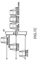
- FIG. 7A describes band-pass characteristic of the first wavelength division multiplexer (MD_MUX#1) 140.
- the multiplexer/demultiplexer 150 multiplexes a plurality of downstream data service signals outputted from the first wavelength division multiplexer (WD_MUX#1) 140 and demultiplexes upstream data service signals transmitted through the second wavelength division multiplexer (WD_MUX#2) 160.
- Multiplexer/demultiplexer 150 is preferably composed of 1 ⁇ N waveguide grating router (WGR).
- the second wavelength division multiplexer (WD_MUX#2) 160 multiplexes the multiplexed signals inputted from the multiplexer/demultiplexer 150 and the multiplexed signals inputted from the downstream broadcasting optical source 130, and demultiplexes upstream data service signals inputted from the local office 200 to output the demultiplexed signals to the multiplexer/demultiplexer 150. That is, the second wavelength division multiplexer (WD_MUX#2) 160 has an operation characteristic which passes the wavelength-division-multiplexed optical signals for upstream/downstream data service and the signals of the downstream broadcasting optical source.
- the second wavelength division multiplexer (WD_MUX#2) 160 it is therefore possible for the second wavelength division multiplexer (WD_MUX#2) 160 to include a fifth band-pass filter having the same band-pass as a wavelength band of wavelength-division-multiplexed optical signals for upstream/downstream data service by the operation characteristic and a sixth band-pass filter having the same band-pass as a preset wavelength band of the downstream optical source 130.
- FIG. 7B describes band-pass characteristic of the second wavelength division multiplexer (MD_MUX#2) 160.
- the central office 100 preferably further comprises an optical amplifier (for example, an erbium-doped fiber amplifier) on an optical fiber connected to the local office 200 to amplify the downstream signals outputted from, and the upstream signals inputted to, the second wavelength division multiplexer (WD_MUX#2) 160.
- an optical amplifier for example, an erbium-doped fiber amplifier
- the local office 200 comprises a multiplexer/demultiplexer 210 which demultiplexes multiplexed optical signals for downstream data service and multiplexed optical signals for downstream broadcasting service transmitted from the central office 100 and multiplexes upstream optical signals transmitted from the subscriber terminals 300. It is preferred that the multiplexer/demultiplexer 210 be implemented as a 1 ⁇ N waveguide grating router (WGR).
- WGR waveguide grating router
- the subscriber terminal 300 comprises a third wavelength division multiplexer (WD_MUX#3) 340, an upstream optical source 310, a downstream data receiver 320 and a downstream broadcasting receiver 330.
- WD_MUX#3 third wavelength division multiplexer
- the third wavelength division multiplexer (WD_MUX#3) 340 demultiplexes optical signals transmitted downstream from the local office 200 and divides them for downstream data service and for downstream broadcasting service.
- the third wavelength division multiplexer (WD_MUX#3) 340 also multiplexes optical signals for upstream transmission from the subscriber terminal 300 to the local office 200 and outputs the multiplexed optical signals.
- the third wavelength division multiplexer (WD_MUX#3) 340 can be configured with a seventh band-pass filter for passing the wavelength band of the upstream optical source 310, an eighth band-pass filter for passing optical signals for downstream data service, and a ninth band-pass filter for passing the optical signals for downstream broadcasting service, according to the operation characteristic. That is, because the third wavelength division multiplexer (WD_MUX#3) 340 has as an operation characteristic the function of passing the signals of the upstream optical source 310, the signals of the downstream data optical source 110, and the signals the downstream broadcasting optical source 130.
- FIG. 7C is a spectrum illustrating band-pass characteristic of the third wavelength division multiplexer (MD_MUX#3) 340.
- the upstream optical source 310 generates optical signals for upstream transmission to the local office 200 through the third wavelength division multiplexer (WD_MUX#3) 340.
- the band-pass of the optical signals generated from the upstream optical source 310 is preferably confined to a different band-pass from that of the optical signals for downstream data service as well as a different band-pass from that of the optical signals for downstream broadcasting service.
- the downstream data receiver 320 receives optical signals for downstream data service demultiplexed by the third wavelength division multiplexer (WD_MUX#3) 340 and converts the received optical signals to electric signals.
- the downstream broadcasting receiver 330 receives optical signals for downstream broadcasting service demultiplexed by the third wavelength division multiplexer (WD_MUX#3) 340 and converts the received optical signals, to electric signals.
- WD_MUX#3 third wavelength division multiplexer
- optical signals generated from the downstream data optical source 110 and the downstream broadcasting optical source 130 in the central office 100 are multiplexed by the second wavelength division multiplexer (WD_MUX#2) 160 and are transmitted to the local office 200.
- the multiplexer/demultiplexer 210 in the local office 200 demultiplexes the multiplexed signals, and divides the data service and broadcasting service optical signals for respective output to each pertinent channel.
- WGR waveguide grating router
- FSR free spectrum range
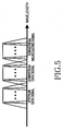
- FIG. 5 is an exemplary conceptual diagram illustrating the spectra of multiplexed WDM optical signals for data service and for broadcasting service and a spectrum of multiplexed upstream optical signals, the spectra being mutually distinct by virtue of their respective disposition within the free spectrum range (FSR) of the WGR.
- FSR free spectrum range
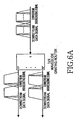
- FIG. 6A is an exemplary conceptual diagram illustrating a spectrum of channel signals for data service and for broadcasting service which are outputted to each subscriber terminal after being demultiplexed by the multiplexer/demultiplexer 210 in the local office 200.
- FIG. 6B is an exemplary conceptual diagram illustrating a spectrum of upstream signals outputted from the multiplexer/demultiplexer 210 in the local office 200.
- Optical signals for data service and the optical signals for broadcasting service are demultiplexed by the multiplexer/demultiplexer 210 for output to respective third wavelength division multiplexers (WD_MUX#3) 340.
- WDMs further demultiplex the received signals into optical signals that optical receivers 320, 330 convert into electrical signals.
- upstream optical signals which are outputted from the upstream optical source 310 are transmitted to the local office 200 through the third wavelength division multiplexer (WD_MUX#3) 340 and are then multiplexed by the multiplexer/demultiplexer 210.
- the latter multiplexed signals are transmitted to the central office 100, where they are demultiplexed in the multiplexer/demultiplexer 150 after passing through the second wavelength division multiplexer (WD_MUX#2) 160.
- the signals are then passed through the first wavelength division multiplexer (WD_MUX#1) 140 and are transmitted to the upstream optical receiver 120 to be convert to electric signals.
- the WDM optical source according to the present invention adopts a spectrum-slicing method that advantageously relieves the need for a WDM optical source with a specific generation wavelength or a wavelength-stabilizing circuit for stabilizing wavelength.
- the WDM optical source according to the present invention also provides WDM signals with high power and very narrow line width, and therefore a broadcasting service without signal distortion by a chromatic dispersion effect. Nor is there a need for an additional amplifier and/or external modulator, which are expensive and whose implementation would economically burden subscribers.
Landscapes
- Engineering & Computer Science (AREA)
- Computer Networks & Wireless Communication (AREA)
- Signal Processing (AREA)
- Physics & Mathematics (AREA)
- Electromagnetism (AREA)
- Optical Communication System (AREA)
- Lasers (AREA)
Applications Claiming Priority (2)
| Application Number | Priority Date | Filing Date | Title |
|---|---|---|---|
| KR10-2003-0002622A KR100520604B1 (ko) | 2003-01-15 | 2003-01-15 | 파장분할다중방식 광원 및 이를 이용한 수동형 광 가입자망시스템 |
| KR2003002622 | 2003-01-15 |
Publications (2)
| Publication Number | Publication Date |
|---|---|
| EP1439645A2 true EP1439645A2 (de) | 2004-07-21 |
| EP1439645A3 EP1439645A3 (de) | 2007-06-20 |
Family
ID=32588954
Family Applications (1)
| Application Number | Title | Priority Date | Filing Date |
|---|---|---|---|
| EP04000024A Withdrawn EP1439645A3 (de) | 2003-01-15 | 2004-01-02 | WDM optische Quelle und damit ausgerüstete passive optische Netzwerkeinrichtung |
Country Status (4)
| Country | Link |
|---|---|
| US (1) | US7272316B2 (de) |
| EP (1) | EP1439645A3 (de) |
| JP (1) | JP3943549B2 (de) |
| KR (1) | KR100520604B1 (de) |
Cited By (2)
| Publication number | Priority date | Publication date | Assignee | Title |
|---|---|---|---|---|
| CN100454788C (zh) * | 2004-10-27 | 2009-01-21 | 华为技术有限公司 | 一种无源光网络 |
| EP3547574A1 (de) * | 2018-03-28 | 2019-10-02 | Fujitsu Limited | Wellenlängenmultiplex-übertragungsvorrichtung und übertragungsverfahren |
Families Citing this family (20)
| Publication number | Priority date | Publication date | Assignee | Title |
|---|---|---|---|---|
| KR100325687B1 (ko) * | 1999-12-21 | 2002-02-25 | 윤덕용 | 주입된 비간섭성 광에 파장 잠김된 페브리-페롯 레이저다이오드를 이용한 파장분할 다중방식 광통신용 광원 |
| US7256930B2 (en) * | 2003-04-15 | 2007-08-14 | Jian Liu | High power pulse shaping fiber laser for high data rate free space telecommunication systems |
| KR100955129B1 (ko) * | 2003-05-30 | 2010-04-28 | 정보통신연구진흥원 | 비간섭성 광대역 광원을 이용한 파장분할다중방식 수동형 광 네트워크 구현 방법 |
| KR100678245B1 (ko) | 2004-12-01 | 2007-02-02 | 삼성전자주식회사 | 수동형 광 가입자 망 |
| KR100678256B1 (ko) * | 2005-01-12 | 2007-02-02 | 삼성전자주식회사 | 파장 분할다중 방식 수동형 광 가입자 망 |
| KR100692194B1 (ko) * | 2005-07-21 | 2007-03-09 | 광주과학기술원 | 파장분할 다중화 기반의 라디오 오버 파이버 시스템용 전광업 컨버터 |
| KR100698766B1 (ko) * | 2005-09-07 | 2007-03-23 | 한국과학기술원 | 파장분할 다중방식 수동형 광 가입자 망 시스템에 사용되는장애 위치 감시 장치 및 이를 구비한 파장분할 다중방식수동형 광 가입자 망 시스템 |
| KR100785436B1 (ko) * | 2005-09-20 | 2007-12-13 | 한국과학기술원 | 방송 서비스와 통신 서비스를 융합한 파장분할 다중방식수동형 광 가입자망 |
| JP4646773B2 (ja) * | 2005-10-06 | 2011-03-09 | 日本放送協会 | 局側終端装置及び光送信機並びに加入者側終端装置 |
| CN101043287B (zh) * | 2006-03-24 | 2012-02-22 | 华为技术有限公司 | 波分复用的无源光网络的传输方法和系统 |
| US8571410B2 (en) | 2006-10-11 | 2013-10-29 | Novera Optics, Inc. | Mutual wavelength locking in WDM-PONS |
| GB0722204D0 (en) * | 2007-11-13 | 2007-12-19 | Ct For Integrated Photonics Th | Real-time data transfer system using a wavelength division multiplexed passive optical network |
| WO2009122577A1 (ja) * | 2008-04-02 | 2009-10-08 | 三菱電機株式会社 | 光通信システム、親局装置および子局装置 |
| JP2010010986A (ja) | 2008-06-26 | 2010-01-14 | Fujikura Ltd | 4光波混合を利用した光伝送システム |
| JP5305377B2 (ja) | 2008-06-26 | 2013-10-02 | 株式会社フジクラ | ラマン光増幅を用いた光伝送システム |
| CN104541151A (zh) * | 2012-05-04 | 2015-04-22 | 美国地震系统有限公司 | 光纤感测系统及其操作方法 |
| US9197352B2 (en) * | 2013-03-11 | 2015-11-24 | Google Inc. | Increasing the capacity of a WDM-PON with wavelength reuse |
| CN104702338B (zh) * | 2013-12-10 | 2017-12-01 | 华为技术有限公司 | 一种信号处理方法以及光接收装置 |
| KR102005832B1 (ko) * | 2018-02-21 | 2019-08-01 | 주식회사 올리브헬스케어 | 생체 신호를 분석하는 신호 처리 장치 및 이를 이용한 생체 신호 분석 장치 |
| US11631431B2 (en) | 2021-07-02 | 2023-04-18 | Seagate Technology Llc | Analog optical link for a moveable actuator in a data storage system |
Citations (3)
| Publication number | Priority date | Publication date | Assignee | Title |
|---|---|---|---|---|
| EP0938169A2 (de) * | 1998-02-18 | 1999-08-25 | Lucent Technologies Inc. | Hochleistungs-Multiwellenlängenlichtquelle |
| EP1024541A2 (de) * | 1999-01-28 | 2000-08-02 | NEC Corporation | Lichtquelle zur Ausstrahlung von Licht verschiedener Wellenlängen und zugehörige optische Übertragungsvorrichtung |
| US20010004290A1 (en) * | 1999-12-21 | 2001-06-21 | Lee Chang Hee | Low-cost WDM source with an incoherent light injected fabry-perot laser diode |
Family Cites Families (11)
| Publication number | Priority date | Publication date | Assignee | Title |
|---|---|---|---|---|
| DE69028497T2 (de) * | 1989-12-20 | 1997-02-06 | Canon Kk | Polarisierendes Beleuchtungsgerät |
| US5073830A (en) * | 1990-01-09 | 1991-12-17 | Greyhawk Systems, Inc. | High-efficiency polarized light source |
| JP2823649B2 (ja) * | 1990-04-05 | 1998-11-11 | 旭光学工業株式会社 | 光束合成装置 |
| ATE162921T1 (de) * | 1990-05-08 | 1998-02-15 | Canon Kk | Polarisationsumsetzungsapparat |
| US5115305A (en) * | 1990-07-05 | 1992-05-19 | Baur Thomas G | Electrically addressable liquid crystal projection system with high efficiency and light output |
| JPH1093164A (ja) | 1996-09-17 | 1998-04-10 | Kokusai Denshin Denwa Co Ltd <Kdd> | 多波長光源及び離散波長可変光源 |
| US5742414A (en) * | 1996-09-24 | 1998-04-21 | At&T Corp. | Multiplicity of services via a wavelength division router |
| US6577422B1 (en) * | 1998-02-18 | 2003-06-10 | At&T Corp. | Long reach delivery of broadcast services using broadband optical sources and pre-compensation dispersion |
| JP3694636B2 (ja) | 2000-06-14 | 2005-09-14 | 日本電信電話株式会社 | 光フィルタ |
| US7286761B2 (en) * | 2000-08-03 | 2007-10-23 | At&T Corp. | Method of flexible multiple broadcast service delivery over a WDM passive optical network based on RF Block-conversion of RF service bands within wavelength bands |
| US7155127B2 (en) * | 2001-08-15 | 2006-12-26 | Nippon Telegraph And Telephone Corporation | Optical communication system, optical communication unit, and optical transceiving package |
-
2003
- 2003-01-15 KR KR10-2003-0002622A patent/KR100520604B1/ko not_active IP Right Cessation
- 2003-08-18 US US10/642,778 patent/US7272316B2/en not_active Expired - Fee Related
-
2004
- 2004-01-02 EP EP04000024A patent/EP1439645A3/de not_active Withdrawn
- 2004-01-15 JP JP2004008512A patent/JP3943549B2/ja not_active Expired - Fee Related
Patent Citations (3)
| Publication number | Priority date | Publication date | Assignee | Title |
|---|---|---|---|---|
| EP0938169A2 (de) * | 1998-02-18 | 1999-08-25 | Lucent Technologies Inc. | Hochleistungs-Multiwellenlängenlichtquelle |
| EP1024541A2 (de) * | 1999-01-28 | 2000-08-02 | NEC Corporation | Lichtquelle zur Ausstrahlung von Licht verschiedener Wellenlängen und zugehörige optische Übertragungsvorrichtung |
| US20010004290A1 (en) * | 1999-12-21 | 2001-06-21 | Lee Chang Hee | Low-cost WDM source with an incoherent light injected fabry-perot laser diode |
Non-Patent Citations (1)
| Title |
|---|
| LEE J S ET AL: "SPECTRUM-SLICED FIBER AMPLIFIER LIGHT SOURC FOR MULTICHANNEL WDM APPLICATIONS" IEEE PHOTONICS TECHNOLOGY LETTERS, IEEE SERVICE CENTER, PISCATAWAY, NJ, US, vol. 5, no. 12, 1 December 1993 (1993-12-01), pages 1458-1461, XP000432998 ISSN: 1041-1135 * |
Cited By (3)
| Publication number | Priority date | Publication date | Assignee | Title |
|---|---|---|---|---|
| CN100454788C (zh) * | 2004-10-27 | 2009-01-21 | 华为技术有限公司 | 一种无源光网络 |
| EP3547574A1 (de) * | 2018-03-28 | 2019-10-02 | Fujitsu Limited | Wellenlängenmultiplex-übertragungsvorrichtung und übertragungsverfahren |
| US10972188B2 (en) | 2018-03-28 | 2021-04-06 | Fujitsu Limited | Transmission apparatus and transmission method |
Also Published As
| Publication number | Publication date |
|---|---|
| KR20040065596A (ko) | 2004-07-23 |
| JP3943549B2 (ja) | 2007-07-11 |
| KR100520604B1 (ko) | 2005-10-10 |
| EP1439645A3 (de) | 2007-06-20 |
| US7272316B2 (en) | 2007-09-18 |
| JP2004222304A (ja) | 2004-08-05 |
| US20040136716A1 (en) | 2004-07-15 |
Similar Documents
| Publication | Publication Date | Title |
|---|---|---|
| US7272316B2 (en) | Wavelength-division-multiplexed optical source and passive optical network system employing the same | |
| KR100480540B1 (ko) | 광가입자단의 파장제어가 가능한 파장분할다중방식 수동형광가입자망 시스템 | |
| JP4584584B2 (ja) | 波長分割多重パッシーブ光ネットワークを含むシステムおよびそのための方法 | |
| KR100875922B1 (ko) | Wdm 수동형 광가입자망에서의 파장 무의존 광원을이용한 하향 광송신 장치 및 그 방법과, 그를 이용한광선로 종단 시스템 | |
| US7389048B2 (en) | Optical wavelength-division multiple access system and optical network unit | |
| EP2157722B1 (de) | WDM-PON Architektur zur Überlagerung eines analogen Signales unter Verwendung von Quanten-Dot Mehrwellenlängenlaserquellen | |
| US9008513B2 (en) | Wavelength division multiplexing-passive optical network system | |
| KR101855716B1 (ko) | 수동 광 파장 분할 다중화 네트워크를 위한 광 회선 단말 | |
| JP4876172B2 (ja) | 波長非依存wdm受動型光加入者網のためのolt及びonu装置及び方法 | |
| US20100266283A1 (en) | Wdm pon with distribution via cyclic array waveguide grating | |
| KR20100092853A (ko) | 저잡음 다파장 광원을 구비한 저잡음 광신호의 전송 장치, 저잡음 다파장 광원을 이용한 방송 신호 전송 장치, 및 이를 구비한 광가입자망 | |
| US8538262B2 (en) | Color free WDM PON based on broadband optical transmitters | |
| US20100046950A1 (en) | Seeding wdm pon system based on quantum dot multi-wavelength laser source | |
| KR100734829B1 (ko) | 광 전송 장치 및 방법 | |
| KR100724901B1 (ko) | 인터리버를 구비한 파장분할다중 방식의 수동형 광가입자망 | |
| RU2009114694A (ru) | Устройство и способ для терминала оптической линии (olt) и модуля оптической сети (onu) в независимых от длины волны пассивных оптических сетях с мультиплексированием с разделением по длине волны | |
| US20050259988A1 (en) | Bi-directional optical access network | |
| WO2009078608A2 (en) | Optical network system for providing wireless broadband services | |
| EP1503531A2 (de) | WDM passives, optisches Netzwerk unter Verwendung von Mehrwellenlängenlaserquellen und reflektierenden, optischen Verstärkungsmitteln | |
| Reichmann et al. | Delivery of 240 broadcast digital video channels to 1024 subscribers on a 1.3-μm spectrally sliced PDFA amplified PON | |
| KR100982207B1 (ko) | 초고주파 대역 결합기 및 이를 이용한 네트워크 시스템 | |
| KR20160035482A (ko) | 싸이클릭 배열 도파로 라우터를 이용한 수동 광 네트워크 시스템 |
Legal Events
| Date | Code | Title | Description |
|---|---|---|---|
| PUAI | Public reference made under article 153(3) epc to a published international application that has entered the european phase |
Free format text: ORIGINAL CODE: 0009012 |
|
| 17P | Request for examination filed |
Effective date: 20040102 |
|
| AK | Designated contracting states |
Kind code of ref document: A2 Designated state(s): AT BE BG CH CY CZ DE DK EE ES FI FR GB GR HU IE IT LI LU MC NL PT RO SE SI SK TR |
|
| AX | Request for extension of the european patent |
Extension state: AL LT LV MK |
|
| PUAL | Search report despatched |
Free format text: ORIGINAL CODE: 0009013 |
|
| AK | Designated contracting states |
Kind code of ref document: A3 Designated state(s): AT BE BG CH CY CZ DE DK EE ES FI FR GB GR HU IE IT LI LU MC NL PT RO SE SI SK TR |
|
| AX | Request for extension of the european patent |
Extension state: AL LT LV MK |
|
| 17Q | First examination report despatched |
Effective date: 20071127 |
|
| AKX | Designation fees paid |
Designated state(s): DE FR GB |
|
| RBV | Designated contracting states (corrected) |
Designated state(s): DE FR GB |
|
| STAA | Information on the status of an ep patent application or granted ep patent |
Free format text: STATUS: THE APPLICATION IS DEEMED TO BE WITHDRAWN |
|
| 18D | Application deemed to be withdrawn |
Effective date: 20091210 |