EP1439631A2 - Method and mechanism for the production of energy - Google Patents
Method and mechanism for the production of energy Download PDFInfo
- Publication number
- EP1439631A2 EP1439631A2 EP04386001A EP04386001A EP1439631A2 EP 1439631 A2 EP1439631 A2 EP 1439631A2 EP 04386001 A EP04386001 A EP 04386001A EP 04386001 A EP04386001 A EP 04386001A EP 1439631 A2 EP1439631 A2 EP 1439631A2
- Authority
- EP
- European Patent Office
- Prior art keywords
- energy
- production
- wheels
- rings
- torque
- Prior art date
- Legal status (The legal status is an assumption and is not a legal conclusion. Google has not performed a legal analysis and makes no representation as to the accuracy of the status listed.)
- Withdrawn
Links
Images

Classifications
-
- H—ELECTRICITY
- H02—GENERATION; CONVERSION OR DISTRIBUTION OF ELECTRIC POWER
- H02K—DYNAMO-ELECTRIC MACHINES
- H02K53/00—Alleged dynamo-electric perpetua mobilia
-
- F—MECHANICAL ENGINEERING; LIGHTING; HEATING; WEAPONS; BLASTING
- F03—MACHINES OR ENGINES FOR LIQUIDS; WIND, SPRING, OR WEIGHT MOTORS; PRODUCING MECHANICAL POWER OR A REACTIVE PROPULSIVE THRUST, NOT OTHERWISE PROVIDED FOR
- F03G—SPRING, WEIGHT, INERTIA OR LIKE MOTORS; MECHANICAL-POWER PRODUCING DEVICES OR MECHANISMS, NOT OTHERWISE PROVIDED FOR OR USING ENERGY SOURCES NOT OTHERWISE PROVIDED FOR
- F03G7/00—Mechanical-power-producing mechanisms, not otherwise provided for or using energy sources not otherwise provided for
-
- F—MECHANICAL ENGINEERING; LIGHTING; HEATING; WEAPONS; BLASTING
- F05—INDEXING SCHEMES RELATING TO ENGINES OR PUMPS IN VARIOUS SUBCLASSES OF CLASSES F01-F04
- F05B—INDEXING SCHEME RELATING TO WIND, SPRING, WEIGHT, INERTIA OR LIKE MOTORS, TO MACHINES OR ENGINES FOR LIQUIDS COVERED BY SUBCLASSES F03B, F03D AND F03G
- F05B2260/00—Function
- F05B2260/40—Transmission of power
- F05B2260/403—Transmission of power through the shape of the drive components
- F05B2260/4031—Transmission of power through the shape of the drive components as in toothed gearing
- F05B2260/40311—Transmission of power through the shape of the drive components as in toothed gearing of the epicyclic, planetary or differential type
-
- H—ELECTRICITY
- H02—GENERATION; CONVERSION OR DISTRIBUTION OF ELECTRIC POWER
- H02K—DYNAMO-ELECTRIC MACHINES
- H02K7/00—Arrangements for handling mechanical energy structurally associated with dynamo-electric machines, e.g. structural association with mechanical driving motors or auxiliary dynamo-electric machines
- H02K7/10—Structural association with clutches, brakes, gears, pulleys or mechanical starters
- H02K7/116—Structural association with clutches, brakes, gears, pulleys or mechanical starters with gears
Definitions
- the present invention relates to the field of the art of methods, means and mechanisms for the production of energy at an extremely high efficiency and more specifically it proposes a method and a mechanism based in the simultaneous exploitation of an action exerted on a system and of the reaction being associated with that action, wherein the proposed method and mechanism succeed in producing energy with a controlled and adjustable with an absolute accuracy at a desired predetermined level, torque and power output.
- the object of the present invention to advantageously overcome the disadvantages and drawbacks of the prior art and propose a method and mechanism, the employment of which will lead to advantageously overcoming the disadvantages and drawbacks of the prior art and to ensuring the production of energy with a high efficiency, wherein the proposed method and mechanism are based on the theory of a simultaneous exploitation of the action exerted on a system and of the reaction produced thereby and wherein the proposed method and mechanism achieve the production of energy with controlled, adjustable with an absolute precision at a desirable predetermined level, parameters of torque and motive power.
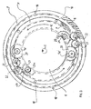
- the device of the invention includes sequential steps of transformation of motion, constituted from flywheels, series of toothed wheels (gears) with suitably selected accessories, such as bearings, spacers, wedges, etc., all of which are arranged in the perimeter of a central principal shaft 2.
- the device of the invention is put in operation when by means of any desirable, conventional and known in the prior art, suitable and available mode and means, is provided a certain quantity of initial energy, e.g. from the power supplying motor that is not depicted.
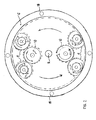
- Three sequential flywheel units 3, 4, 5 are mounted along the principal central axis 2 of the device in between the bottom basement 1 and the upper cover 15 thereof.
- Three rings 6, 7 and 8 are mounted, again from the bottom to the top of central shaft 2, having progressively increasing diameters, so that the diameter of fixedly mounted ring 8 is bigger than that of ring 7 and the diameter of ring 7 is bigger than that of ring 6.
- the three rings are mounted in the circumference of the device, being fixedly mounted via suitable pillars 18 in the basement 1 of the device. All three fixedly mounted rings 6, 7 and 8 are provided with a circumferential internal toothing.
- the power supply motor that is not portrayed in the drawings is engaged with the denture of the first bottom flywheel 3.
- the kinetic energy is thereby transferred from flywheel 3 on the one hand in the series of double toothed wheels 9 that are pivotally mounted within suitable bearings and on the other hand in the shafts 13 of flywheel 4 extending on either side of the principal shaft 2 of the device.
- each pair of wheels 9 corresponds an underlying wheel 9a of smaller diameter, wherein the wheels 9a are engaged in the circumferential first fixed ring 6 and, as it appears in Fig. 2, two such series of double toothed wheels 9 are arranged in diametrically opposing positions in the perimeter of ring 6.
- two such series of double toothed wheels 9 are arranged in diametrically opposing positions in the perimeter of ring 6.
- Wheels 25 move in the circumference of the fixed wheel with external denture 11, whilst the wheels 25a engaged in the wheel 11 a of the generator shaft 26 supply the energy required by the system.
- wheels 10 being engaged with wheels 9 result in the increase of torque in the shafts 19 of wheels 9 ⁇ 9a, as the wheels 9a move around the circumference of the first fixed ring 6 and they simultaneously perform a rotation around their own axis.
- wheels 9a' and 20 that lie above the wheels 9-9a along the same axis with the latter to wheels that are engaged with the third fixed ring with internal denture 8.
- wheels 9a' having the same diameter as the wheels 9a, are engaged to the second internally toothed fixed ring 7 and move around the circumference thereof, thereby providing the torque increased during the second stage to the overlying wheels of bigger diameter 20.
- free toothed wheels 21 that transfer the motion in the wheels 22 that have the same diameter and move around the circumference of the third internally toothed fixed ring 8, providing a resultant still further increased torque.
- the device of the invention was tried in operation by the Swedish company V ⁇ STKUSTKRAFT AB.
- the measuring instrumentation used in the test was equipped with an electric motor, of the asynchronous 3-phase and of a nominal capacity 2.25 kVA type.
- the motor was connected in series with an on-off switch and starter with a three phase durable adjustable resistor of 3.0 kVA.
- the electric energy was supplied through a suitable voltage potentiometer with a safety fuse 3X20 A, connected through a D form quadrapolar conductive wire.
- a single phase synchronous self magnetized generator of an optimum capacity of 1.5 KVA at 3000 revs was mounted onto the output shaft.
- the Measurement was carried out only in the engine, not including the rheostatic resistance.
- the measuring instrument Fluke 43 was used for the recordal of voltage and current. This instrument records these parameters, as well as the frequency and the intermediate - transitory produced parameters and it displays all the electric parameters, that are essential and relevant in the framework of the measurement and specific order to the testing company V ⁇ STKUSTKRAFT AB.
- the instrument was put in operation and measurements were carried out three times. It was the third time that the maximum revs amounting to 95% of the nominal value at 50 Hz was recorded in the resulting output. This corresponds in a number of revs at the generator of the order of 2.850 rpm.
- the device did not present any problem during these measurements, but the number of revs was decreased for the sake of safety of those present and for avoiding damages being produced in the invented device.
- the device was put in operation, but the measurement stopped after 17 seconds as the frequency of 28.8 Hz was reached, in order to correct a calibration problem encountered with the measuring instrument FLUKE 43.
- the device was put in operation and the number of revs was continuously increased up to a value close to approximately 95% of the total number of revs that could be reached by a synchronous generator. At a value of approximately 62% of the nominal number of revs a voltage was measured at the generator that started to supply energy to the load imposed to the device. This was manifested more clearly when the noise of the instrument became more intense.
- the rheostatic resistance was regulated also for higher voltage values, so that the number of revs would not need to be decreased.
- the first measurement was recorded at the 89% of the total number of revs. At the 95% of the total number of revs of the generator, the power produced was logarithmically increased and it was at this rpm value that 0.77 kW was produced. The power supplied at this instant was 0.77 kW. Such measurement is remarkable of course if one takes into account the expected losses of the device itself.
- the device entered in operation the number of revs was increased and energy was produced by the generator.
- the power produced by the generator was 0.92 kW at cos ⁇ 1.0.
- the power input at this particular moment was 0.88 kW.
- the measurement lasted 94 seconds, as long as it was judged advisable in order to avoid any danger for those present in the test procedure.
- the 95% of the total number of revs was kept constant for a period of 32 seconds. Throughout these 32 seconds the power output was higher than the power input.
Landscapes
- Engineering & Computer Science (AREA)
- Chemical & Material Sciences (AREA)
- Combustion & Propulsion (AREA)
- Power Engineering (AREA)
- Mechanical Engineering (AREA)
- General Engineering & Computer Science (AREA)
- Connection Of Motors, Electrical Generators, Mechanical Devices, And The Like (AREA)
- Retarders (AREA)
Abstract
Description
| Resultant energy | Fluke 41 B | |
| Supplement in the input voltage | Beckman T 110 B | |
| Resultant output, energy, sinusoidal wave, as well as intermediate-transitory parameters and voltage, as well as recording of | Fluke | 43 |
| Supplement in the output voltage | Fluke 87 |
Claims (7)
- Mechanism for the production of energy characterized by that its operation is based in the simultaneous exploitation of an action exerted on a system and of the reaction being associated with that action, wherein the proposed mechanism receives an in initial power input and is capable of producing energy with a controlled and adjustable with an absolute accuracy at a desired predetermined level, torque and power output at a shaft (26) of a generator supplying energy for consumption, said mechanism comprising a plurality of discreet stages arranged longitudinally along and around the perimeter of a fixedly mounted central shaft (2) extending from a bottom basement (1) to a top cover (15), wherein each one of said discreet stages comprises a system of fixed and movable toothed wheels that engage one to the other, certain ones of said fixed and movable toothed wheels performing a rotation around their own axis whilst in the same time performing a rotation around fixed internally toothed perimetrically arranged rings, thereby producing through conversion of the reaction produced to action and given suitable correlation of diameters, a gradually increasing output torque.
- Mechanism for the production of energy according to the above claim 1, characterized by that it comprises three sequential flywheel units (3), (4), (5) fixedly mounted by means of pillars (18) from the bottom basement (1) to the upper cover (15) thereof, three rings (6), (7) and (8) being accordingly mounted, again from the bottom to the top, said three rings having progressively increasing diameters, so that the diameter of fixedly mounted ring (8) is bigger than that of ring (7) and the diameter of ring (7) is bigger than that of ring (6), wherein all three rings (6), (7) and (8) are provided with a circumferential internal toothing and are respectively engaged to planet wheels (9a), (9a') and (22), said planet wheels performing a rotation around themselves whilst proceeding around the perimeter of said rings (6,7,8), thereby producing a gradually and continuously increasing torque that they transfer towards the central shaft (2) of the mechanism whereupon is mounted said shaft (26) of the energy producing generator (17).
- Mechanism for the production of energy according to the above claim 2, characterized by that equidistantly spaced pairs of toothed wheels (9a), (9a') and (22) respectively are mounted at the perimeter of each one of said rings (6,7,8).
- Mechanism for the production of energy according to the above claim 3, characterized by that said equidistantly spaced pairs of toothed wheels (9a), (9a') and (22) respectively mounted at the perimeter of each one of said rings (6,7,8) are two antidiametrically located pairs, the distance in between them corresponding to an arc of 180°.
- Mechanism for the production of energy according to the above claim 3, characterized by that said equidistantly spaced pairs of toothed wheels (9a), (9a') and (22) respectively mounted at the perimeter of each one of said rings (6,7,8) are three circumferentially located pairs, the distance in between them corresponding to an arc of 120°.
- Mechanism for the production of energy according to the above claims 1-5, characterized by that it comprises transmission means of the movement of an uppermost wheel (11a) connected to the shaft (26) of generator (17) wherein is obtained the maximum value of the gradually increasing torque to a lowest said first flywheel (3) corresponding to the input to the system, so as to eliminate, following employment of brake means for adjustment of the desired rpm of the mechanism, needed initial input to the power supplying motor.
- Method for the production of energy based in the simultaneous exploitation of an action exerted on a system and of the reaction being associated with that action, wherein the proposed method receives an in initial power input and is capable of producing energy with a controlled and adjustable with an absolute accuracy at a desired predetermined level, torque and power output at a generator supplying energy for consumption, wherein is employed a mechanism for the production of energy as claimed in any of the above claims 1-6.
Applications Claiming Priority (2)
| Application Number | Priority Date | Filing Date | Title |
|---|---|---|---|
| GR20030100013A GR1004373B (en) | 2003-01-14 | 2003-01-14 | Power regeneration method and mechanism |
| GR2003100013 | 2003-01-14 |
Publications (2)
| Publication Number | Publication Date |
|---|---|
| EP1439631A2 true EP1439631A2 (en) | 2004-07-21 |
| EP1439631A3 EP1439631A3 (en) | 2006-12-06 |
Family
ID=29559962
Family Applications (1)
| Application Number | Title | Priority Date | Filing Date |
|---|---|---|---|
| EP04386001A Withdrawn EP1439631A3 (en) | 2003-01-14 | 2004-01-08 | Method and mechanism for the production of energy |
Country Status (2)
| Country | Link |
|---|---|
| EP (1) | EP1439631A3 (en) |
| GR (1) | GR1004373B (en) |
Cited By (8)
| Publication number | Priority date | Publication date | Assignee | Title |
|---|---|---|---|---|
| WO2006106375A1 (en) * | 2005-04-04 | 2006-10-12 | Tantris Ltd | Device for non reactive propulsion generated from eccentric motions |
| WO2008032133A1 (en) * | 2005-08-17 | 2008-03-20 | Jayantha Liyanage | The dual drive electric regenerator |
| WO2008037014A1 (en) * | 2006-09-29 | 2008-04-03 | Universal Engines Pty Ltd | Force amplification method and apparatus by the harnessing of centrifugal force |
| WO2010147450A1 (en) * | 2009-06-17 | 2010-12-23 | Green-Tech Holdings Sdn Bhd | Uninterrupted battery operated generator system |
| ITAV20100003A1 (en) * | 2010-07-30 | 2012-01-31 | Michele Masiello | "INNOVATIVE MECHANICAL DEVICE THAT, THANKS TO A SERIES OF GEARS OF DIFFERENT DIAMETER, SOME FLYERS FOR THE ACCUMULATION OF ENERGY AND A LARGE SATELLITE USED AS A LEVER, GENERATES WORK" |
| WO2015003205A1 (en) * | 2013-07-07 | 2015-01-15 | Universal Engines Pty Ltd | Self powering energy generation by the harnessing of centrifugal force |
| WO2019091272A1 (en) * | 2017-11-07 | 2019-05-16 | 张志军 | Gradient difference type permanent magnet driver |
| WO2023130154A1 (en) * | 2022-01-07 | 2023-07-13 | Geoffrey William Good Leviny | Energy generator |
Family Cites Families (5)
| Publication number | Priority date | Publication date | Assignee | Title |
|---|---|---|---|---|
| JPS5635676A (en) * | 1979-08-27 | 1981-04-08 | Mitsuaki Inagaki | Electric generator |
| JPH08256470A (en) * | 1993-04-12 | 1996-10-01 | Takashi Nosaka | Rotational force amplifying apparatus, and motor and generation set therefor |
| EP1293029A1 (en) * | 2000-06-20 | 2003-03-19 | Alexander Ellison Rees | Electrical drive line |
| US6433450B1 (en) * | 2000-11-28 | 2002-08-13 | Wen-Ping Chao | Power generating system with physical energy to enhance output |
| DE10208059A1 (en) * | 2001-05-02 | 2002-10-24 | David Evince O'lucky | Electrical amplification generator for domestic and industrial use manipulates electrical current to produce e.g. 4 kW for use from 1 kW from socket, has chassis and several parts |
-
2003
- 2003-01-14 GR GR20030100013A patent/GR1004373B/en unknown
-
2004
- 2004-01-08 EP EP04386001A patent/EP1439631A3/en not_active Withdrawn
Cited By (9)
| Publication number | Priority date | Publication date | Assignee | Title |
|---|---|---|---|---|
| WO2006106375A1 (en) * | 2005-04-04 | 2006-10-12 | Tantris Ltd | Device for non reactive propulsion generated from eccentric motions |
| WO2008032133A1 (en) * | 2005-08-17 | 2008-03-20 | Jayantha Liyanage | The dual drive electric regenerator |
| AU2006348382B2 (en) * | 2005-08-17 | 2013-04-18 | Jayantha Liyanage | The dual drive electric regenerator |
| WO2008037014A1 (en) * | 2006-09-29 | 2008-04-03 | Universal Engines Pty Ltd | Force amplification method and apparatus by the harnessing of centrifugal force |
| WO2010147450A1 (en) * | 2009-06-17 | 2010-12-23 | Green-Tech Holdings Sdn Bhd | Uninterrupted battery operated generator system |
| ITAV20100003A1 (en) * | 2010-07-30 | 2012-01-31 | Michele Masiello | "INNOVATIVE MECHANICAL DEVICE THAT, THANKS TO A SERIES OF GEARS OF DIFFERENT DIAMETER, SOME FLYERS FOR THE ACCUMULATION OF ENERGY AND A LARGE SATELLITE USED AS A LEVER, GENERATES WORK" |
| WO2015003205A1 (en) * | 2013-07-07 | 2015-01-15 | Universal Engines Pty Ltd | Self powering energy generation by the harnessing of centrifugal force |
| WO2019091272A1 (en) * | 2017-11-07 | 2019-05-16 | 张志军 | Gradient difference type permanent magnet driver |
| WO2023130154A1 (en) * | 2022-01-07 | 2023-07-13 | Geoffrey William Good Leviny | Energy generator |
Also Published As
| Publication number | Publication date |
|---|---|
| GR1004373B (en) | 2003-10-23 |
| EP1439631A3 (en) | 2006-12-06 |
Similar Documents
| Publication | Publication Date | Title |
|---|---|---|
| US6731017B2 (en) | Distributed powertrain that increases electric power generator density | |
| RU2423716C2 (en) | Method and device of mechanism monitoring | |
| US6239524B1 (en) | Power conversion methods and apparatus | |
| AU2006200782A1 (en) | Methods and apparatus for pitch control power conversion | |
| US8049353B1 (en) | Stackable generator arrangement | |
| EP1439631A2 (en) | Method and mechanism for the production of energy | |
| JP7146580B2 (en) | Wind power generator and wind power generation system | |
| RU2737738C1 (en) | Test bench for electric drives | |
| ES2555067T3 (en) | Test facility and method for testing gearboxes and electromechanical energy converters | |
| CN209444758U (en) | A kind of direct-drive type harmonic speed reducer transmission device | |
| US10844944B2 (en) | Inverted harmonic gear actuator | |
| US20160201652A1 (en) | System and method for integrating a horizontal axis wind turbine and a vertical axis wind turbine | |
| CA2589083C (en) | Mechanical system for power change between the input and output thereof | |
| CN201541175U (en) | Natural power generating equipment and generator set | |
| CN102025220B (en) | Natural force power generation equipment and generator set | |
| JP2021019500A (en) | Power transmission device | |
| US8517669B2 (en) | Mechanical wind turbine and method of use | |
| CN102418674B (en) | Energy storage wind driven power generation device | |
| CN106712688B (en) | A kind of safe and reliable high-efficiency solar power generator | |
| BR112023005785A2 (en) | WIND TURBINE POWER TRANSMISSION SYSTEM | |
| SU1796044A3 (en) | Multiflow double-stage reduction gear of bearing transmission unit of wind-driven power plant | |
| WO2008053494A1 (en) | An engine to convert gravitational energy into electrical energy | |
| JP2006144598A (en) | Step-up gear device for wind turbine device | |
| CN207513690U (en) | Gas Turbine Generating Units and its connection structure | |
| CN203756873U (en) | Planetary difference ring reducer |
Legal Events
| Date | Code | Title | Description |
|---|---|---|---|
| PUAI | Public reference made under article 153(3) epc to a published international application that has entered the european phase |
Free format text: ORIGINAL CODE: 0009012 |
|
| AK | Designated contracting states |
Kind code of ref document: A2 Designated state(s): AT BE BG CH CY CZ DE DK EE ES FI FR GB GR HU IE IT LI LU MC NL PT RO SE SI SK TR |
|
| AX | Request for extension of the european patent |
Extension state: AL HR LT LV MK |
|
| 17P | Request for examination filed |
Effective date: 20050120 |
|
| PUAL | Search report despatched |
Free format text: ORIGINAL CODE: 0009013 |
|
| AK | Designated contracting states |
Kind code of ref document: A3 Designated state(s): AT BE BG CH CY CZ DE DK EE ES FI FR GB GR HU IE IT LI LU MC NL PT RO SE SI SK TR |
|
| AX | Request for extension of the european patent |
Extension state: AL LT LV MK |
|
| AKX | Designation fees paid |
Designated state(s): AT BE BG CH CY CZ DE DK EE ES FI FR GB GR HU IE IT LI LU MC NL PT RO SE SI SK TR |
|
| STAA | Information on the status of an ep patent application or granted ep patent |
Free format text: STATUS: THE APPLICATION IS DEEMED TO BE WITHDRAWN |
|
| 18D | Application deemed to be withdrawn |
Effective date: 20120801 |