EP1439554A1 - Inductive component - Google Patents
Inductive component Download PDFInfo
- Publication number
- EP1439554A1 EP1439554A1 EP04100016A EP04100016A EP1439554A1 EP 1439554 A1 EP1439554 A1 EP 1439554A1 EP 04100016 A EP04100016 A EP 04100016A EP 04100016 A EP04100016 A EP 04100016A EP 1439554 A1 EP1439554 A1 EP 1439554A1
- Authority
- EP
- European Patent Office
- Prior art keywords
- core
- elements
- inductive component
- stack
- magnetic
- Prior art date
- Legal status (The legal status is an assumption and is not a legal conclusion. Google has not performed a legal analysis and makes no representation as to the accuracy of the status listed.)
- Withdrawn
Links
- 230000001939 inductive effect Effects 0.000 title claims abstract description 76
- 238000004804 winding Methods 0.000 claims abstract description 64
- 230000004907 flux Effects 0.000 claims abstract description 26
- 238000000034 method Methods 0.000 claims abstract description 7
- 239000000463 material Substances 0.000 claims description 5
- 238000001816 cooling Methods 0.000 claims description 4
- 239000000853 adhesive Substances 0.000 claims description 3
- 230000001070 adhesive effect Effects 0.000 claims description 3
- 239000011162 core material Substances 0.000 description 56
- 239000000696 magnetic material Substances 0.000 description 13
- 230000008878 coupling Effects 0.000 description 8
- 238000010168 coupling process Methods 0.000 description 8
- 238000005859 coupling reaction Methods 0.000 description 8
- 239000004411 aluminium Substances 0.000 description 2
- 229910052782 aluminium Inorganic materials 0.000 description 2
- XAGFODPZIPBFFR-UHFFFAOYSA-N aluminium Chemical compound [Al] XAGFODPZIPBFFR-UHFFFAOYSA-N 0.000 description 2
- 239000004020 conductor Substances 0.000 description 2
- 238000004519 manufacturing process Methods 0.000 description 2
- 230000003071 parasitic effect Effects 0.000 description 2
- 230000035699 permeability Effects 0.000 description 2
- RYGMFSIKBFXOCR-UHFFFAOYSA-N Copper Chemical compound [Cu] RYGMFSIKBFXOCR-UHFFFAOYSA-N 0.000 description 1
- XEEYBQQBJWHFJM-UHFFFAOYSA-N Iron Chemical compound [Fe] XEEYBQQBJWHFJM-UHFFFAOYSA-N 0.000 description 1
- 229910000831 Steel Inorganic materials 0.000 description 1
- 238000004026 adhesive bonding Methods 0.000 description 1
- 230000000712 assembly Effects 0.000 description 1
- 238000000429 assembly Methods 0.000 description 1
- 229910052751 metal Inorganic materials 0.000 description 1
- 239000002184 metal Substances 0.000 description 1
- 239000002707 nanocrystalline material Substances 0.000 description 1
- 238000004806 packaging method and process Methods 0.000 description 1
- 239000010959 steel Substances 0.000 description 1
- 229910000859 α-Fe Inorganic materials 0.000 description 1
Images
Classifications
-
- H—ELECTRICITY
- H01—ELECTRIC ELEMENTS
- H01F—MAGNETS; INDUCTANCES; TRANSFORMERS; SELECTION OF MATERIALS FOR THEIR MAGNETIC PROPERTIES
- H01F37/00—Fixed inductances not covered by group H01F17/00
-
- H—ELECTRICITY
- H01—ELECTRIC ELEMENTS
- H01F—MAGNETS; INDUCTANCES; TRANSFORMERS; SELECTION OF MATERIALS FOR THEIR MAGNETIC PROPERTIES
- H01F3/00—Cores, Yokes, or armatures
- H01F3/10—Composite arrangements of magnetic circuits
-
- H—ELECTRICITY
- H01—ELECTRIC ELEMENTS
- H01F—MAGNETS; INDUCTANCES; TRANSFORMERS; SELECTION OF MATERIALS FOR THEIR MAGNETIC PROPERTIES
- H01F27/00—Details of transformers or inductances, in general
- H01F27/08—Cooling; Ventilating
- H01F27/22—Cooling by heat conduction through solid or powdered fillings
-
- H—ELECTRICITY
- H01—ELECTRIC ELEMENTS
- H01F—MAGNETS; INDUCTANCES; TRANSFORMERS; SELECTION OF MATERIALS FOR THEIR MAGNETIC PROPERTIES
- H01F27/00—Details of transformers or inductances, in general
- H01F27/24—Magnetic cores
- H01F27/26—Fastening parts of the core together; Fastening or mounting the core on casing or support
- H01F27/263—Fastening parts of the core together
-
- H—ELECTRICITY
- H01—ELECTRIC ELEMENTS
- H01F—MAGNETS; INDUCTANCES; TRANSFORMERS; SELECTION OF MATERIALS FOR THEIR MAGNETIC PROPERTIES
- H01F27/00—Details of transformers or inductances, in general
- H01F27/34—Special means for preventing or reducing unwanted electric or magnetic effects, e.g. no-load losses, reactive currents, harmonics, oscillations, leakage fields
-
- H—ELECTRICITY
- H01—ELECTRIC ELEMENTS
- H01F—MAGNETS; INDUCTANCES; TRANSFORMERS; SELECTION OF MATERIALS FOR THEIR MAGNETIC PROPERTIES
- H01F30/00—Fixed transformers not covered by group H01F19/00
- H01F30/06—Fixed transformers not covered by group H01F19/00 characterised by the structure
- H01F30/12—Two-phase, three-phase or polyphase transformers
Definitions
- the present invention relates to an inductive component and to a method for building an inductive component.
- Inductive components in particular inductors, also known as chokes, and transformers, are usually manufactured using one or more windings of a conductive material and a magnetic core of a magnetic material, that is of a material with a relative permeability higher than one.
- the windings and the core are assembled in such a way that the magnetic field generated by the electrical current in the windings causes a magnetic flux to flow within the magnetic core.
- the use of magnetic cores allows for building inductive components with much higher inductivity than that of air-core inductive components, i.e. inductive components without any magnetic core, having the same windings.
- inductive components which can in some cases be built into one single assembly. In other words, it's sometimes possible to integrate multiple inductive components into one.
- inductors and transformers in which the chokes for all three phases are combined into a single inductive component were commonly used.
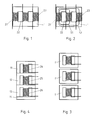
- An example of a prior art three-phase inductor is schematically illustrated in fig. 1.
- This inductive component comprises three windings 21, 22 and 23, made out of a conductive material such as copper wire for example, each winding 21, 22, 23 being wound around one of the three parallel branches of the magnetic core 1.
- Such an assembly is very compact from the packaging and the assembly points of view as all three chokes with the windings 21, 22 and 23 respectively, share the same magnetic core 1, as well as the same mounting structures and connectors.
- the magnetic paths 51 and 52 for the magnetic flux induced in the magnetic core 1 by a current in the first winding 21 of this prior art inductor are illustrated in fig. 2, from where it can be seen that the windings 21, 22 and 23 are magnetically coupled together: the magnetic flux generated by the first winding 21 flows through the other two windings 22 and 23 as well.
- the electrical circuits connected to the windings 21, 22 and 23 are thus also coupled together.
- the interrelation, or flux coupling, between windings for different phases isn't always desired in today's electrical systems, even in today's three-phase electrical systems.
- the prior art three-phase choke illustrated in fig. 1 and in fig. 2 is mainly intended to be used with sinusoidal, non-switched currents and voltages as was the case for most early three-phase electrical systems. Its design is thus based on the assumption that the sum of all phase currents at every moment is equal to zero. In today's power electronic equipments, such as three-phase pulse width modulated (PWM) motor drives for example, this assumption is often not met and the coupling between the different phases of the electrical system may result into parasitic, non-intended currents flowing in the windings.
- PWM pulse width modulated
- a further drawback of prior art integrated inductive components such as the one illustrated in fig. 1 is that their magnetic core is specifically designed to be used with a determined number of windings, thus implying the manufacture of magnetic cores of different shapes in order to build integrated inductive components for use in two-, three- or other multiphase electrical systems.
- An aim of the present invention is thus to provide a compact inductive component for use in multiphase systems avoiding magnetic flux coupling between the different phases.
- Another aim of the present invention is thus to provide a compact inductive component for use in multiphase systems allowing for a significant attenuation of common mode currents.
- Another aim of the present invention is to provide a method for building an inductive component easily adapted for use in different multiphase systems.
- an inductive component comprising a magnetic core and a plurality of windings, the inductive component consisting of an assembly of stack elements each comprising at least one winding and at least one core element, the shortest magnetic path for the magnetic flux induced by the winding or windings of at least one of the stack elements going through part of at least one core element of another stack element without going through any winding of this other stack element, and by a method and a set of core elements for building such an inductive component.
- each of the three windings 24, 25 and 26 is placed around the middle branch of an E-shaped core element 11, 12, respectively 13 made of a magnetic material, thus forming three stack elements.
- the three stack elements 11 and 24, 12 and 25 and 13 and 26 are then assembled such as to build a single inductive component integrating three chokes, whereas the common magnetic material, i.e. all the parts of the assembled magnetic core within which the fluxes of more than one choke can potentially flow, is situated in regions outside either one of the three windings 24, 25 or 26.
- An I-shaped core element 14 is additionally used to close the flux paths of the third choke with winding 26.
- the core elements 11, 12, 13, 14 used in this illustrative example are E- and I-shaped core elements.
- the one skilled in the art will however recognize that other shapes can be used for the basic elements, such as U-or pot-shaped core elements for example, in order to build for instance an inductive component integrating chokes having different mechanical and/or electrical properties.
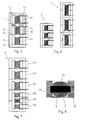
- the magnetic flux paths within the three-phase inductive component are illustrated in more detail in fig. 5.
- Current is assumed to flow in the first and second windings 24 and 25, inducing the fluxes 55, 56 and 57, 58 respectively.
- the fluxes 55 and 56 induced by the current in the first winding 24 find their shortest paths through the external branches of the first E-shaped core element 11. Only a small amount of these fluxes, thus not represented in fig. 4, flows through the external branches of the second and/or third E-shaped core elements 12 and/or 13, resulting in very small magnetic coupling between the chokes.
- the fluxes 57 and 58 induced by the current in the second winding 25 travel in the external branches of the second E-shaped core element 12 only and don't create significant magnetic coupling with the first and third chokes with the windings 24 and 26 respectively.
- Magnetic coupling between the different chokes of a multiphase inductive component according to the invention is thus negligible.
- the multiphase magnetic structure provides impedance, thus attenuation, against common mode currents as well.
- a further advantage of a multiphase inductive component according to the invention is that as the fluxes from different phases such as the fluxes 55, 56 on the one side and fluxes 57, 58 on the other side still share some magnetic material along their paths, the total amount of required magnetic material is reduced compared to the total amount of magnetic material required for building three totally independent chokes as illustrated for example in fig. 3. Because in a three-phase system, for example, the phases of the peak currents, and therefore of the peak flux densities, are shifted by approximately 120 degrees, it is only necessary to provide enough common magnetic material for the peak value of one individual phase. The common magnetic material is thus efficiently shared between the different phases: one phase after another and not simultaneously.
- the assembly of core elements according to the invention is also very efficient since a reduced set of basic magnetic core elements which can be mass-manufactured as standard building blocks can be stacked together in very different ways in order to build many different inductive components.
- Fig. 6 shows for example how just one single type of E-shaped core element and one single type of I-shaped core element are used for building three-phase inductive components 6 and 7 having different characteristics.
- the core elements are laid next to each other.
- the core elements can also be stacked on top of each other in order to build inductive components with different configurations.
- the different core elements of an inductive component according to the invention can also be made of different materials having different magnetic properties, in order for example to adapt the electrical characteristics of the inductive component to the needs of a specific application.
- the inductive components according to the invention are not limited to three-phase electrical systems.
- Other multiphase inductive components can be built by assembling different numbers of stack elements, thus building inductive components to be used for instance in a two- or four-phase electrical system.
- At least some windings of the inventive inductive component can be electrically connected to each other in order to form an electrical circuit having some required characteristics, such as for example higher current capacity in that two or more windings are connected in parallel and/or higher inductance in that two or more windings are connected in series.
- the core elements can also be assembled in order to integrate different types of inductors.
- Fig. 7 shows for example how three differential chokes 211, 212 and 213 and one common mode choke structure 214, 215, 216 are integrated in the same inductive component 8 by assembling the same core elements in a different manner as previously shown.
- the differential mode chokes 211, 212 and 213 and the common mode chokes 214, 215 and 216 can either be connected to the same electrical circuit or can each belong to totally separated electrical circuits.
- the inductive component according to the invention is thus built by the assembly of a certain number of possibly different stack elements made of one or more core elements and of one or more windings, the core elements and the windings of each stack element being arranged so as to obtain the desired electrical and/or mechanical properties for the corresponding stack element.
- the shortest magnetic path for the magnetic flux generated by the winding or windings of one of the stack elements goes through at least part of the core element of another stack element, without going through any of the windings of this other stack element.
- the shortest magnetic path is the path having the lowest reluctance.
- the shortest magnetic path will usually correspond to the physically shortest path, such as the shortest magnetic paths represented for the fluxes 55, 56, 57 and 58 in the example of fig. 5. It can usually be considered that only a very small part of the magnetic fluxes follow other paths than the shortest magnetic path, thus resulting, in the inventive inductive component, in very low magnetic coupling between at least two windings of different stack elements. In other words, at least two of the stack elements share some of their magnetic material, with their chokes being magnetically very weakly coupled.
- the inductive component of fig. 4 is thus constituted of three stack elements.
- the first stack element being made of the core element 11 and the winding 24, the second stack element being made of the core element 12 and the winding 25 and the third stack element including the core elements 13 and 14 as well as the winding 26.
- the inductive components represented in fig. 6 are also assemblies of three stack elements, whereas the inductive component of fig. 7 is an assembly of four stack elements, one of them having a completely different configuration from that of the other three.
- the magnetic material used for the core elements is preferably any magnetic material such as steel, ferrite, iron powder, sinter metal, amorphic or nanocrystalline material.
- the assembled core elements forming the magnetic core of the inductive component are preferably assembled and held together by some assembly means.
- the assembled core elements 10 and windings 20 are for example hosted in a frame 3, for example in an aluminium profile holding all the parts of the inductive component together.
- the frame additionally preferably comprises cooling elements, such as for instance radiators 30, in order to provide the inductive component with cooling.
- the core elements are for instance held together by gluing them to each other with a preferably magnetic adhesive material.
- the core elements comprise profiles designed to cooperate with corresponding profiles on the other core elements. The core elements can then be attached to each other through these profiles.
- the above examples are illustrative but not limiting examples: the one skilled in the art will easily recognize that other types of assembly means can be used in order to hold the core elements together and provide the inductive element with mechanical stability.
- the core elements can be assembled using various mechanical means such as for example bolts inserted through the entire core assembly.
Landscapes
- Engineering & Computer Science (AREA)
- Power Engineering (AREA)
- Chemical & Material Sciences (AREA)
- Composite Materials (AREA)
- Coils Or Transformers For Communication (AREA)
Abstract
Inductive component comprising a magnetic core and a plurality
of windings (24, 25, 26), the inductive component consisting of an assembly
of stack elements each comprising at least one winding and at least one
core element (11, 12, 13, 14), the shortest magnetic path for the magnetic
flux induced by the winding (24) or windings of at least one of the stack
elements going through part of at least one core element (12) of another
stack element without going through any winding (25) of this other stack
element. Method and set of core elements for building such an inductive
component.
Description
- The present invention relates to an inductive component and to a method for building an inductive component.
- Inductive components, in particular inductors, also known as chokes, and transformers, are usually manufactured using one or more windings of a conductive material and a magnetic core of a magnetic material, that is of a material with a relative permeability higher than one. The windings and the core are assembled in such a way that the magnetic field generated by the electrical current in the windings causes a magnetic flux to flow within the magnetic core. The use of magnetic cores allows for building inductive components with much higher inductivity than that of air-core inductive components, i.e. inductive components without any magnetic core, having the same windings.
- Electrical systems often require the use of a plurality of inductive components, which can in some cases be built into one single assembly. In other words, it's sometimes possible to integrate multiple inductive components into one. In three-phase electrical systems for example, inductors and transformers in which the chokes for all three phases are combined into a single inductive component were commonly used. An example of a prior art three-phase inductor is schematically illustrated in fig. 1. This inductive component comprises three
windings magnetic core 1. Such an assembly is very compact from the packaging and the assembly points of view as all three chokes with thewindings magnetic core 1, as well as the same mounting structures and connectors. - The
magnetic paths magnetic core 1 by a current in the first winding 21 of this prior art inductor are illustrated in fig. 2, from where it can be seen that thewindings first winding 21 flows through the other twowindings windings - The interrelation, or flux coupling, between windings for different phases isn't always desired in today's electrical systems, even in today's three-phase electrical systems. The prior art three-phase choke illustrated in fig. 1 and in fig. 2 is mainly intended to be used with sinusoidal, non-switched currents and voltages as was the case for most early three-phase electrical systems. Its design is thus based on the assumption that the sum of all phase currents at every moment is equal to zero. In today's power electronic equipments, such as three-phase pulse width modulated (PWM) motor drives for example, this assumption is often not met and the coupling between the different phases of the electrical system may result into parasitic, non-intended currents flowing in the windings.
- Another drawback of the multiphase inductor represented in fig. 1 and in fig. 2 is that it doesn't provide much attenuation against the so called "common mode currents", which are parasitic currents flowing in the same direction in all the windings of the inductive component, the sum of which isn't thus equal to zero. Common mode currents are the main reason for many electromagnetic interference problems.
- A further drawback of prior art integrated inductive components such as the one illustrated in fig. 1 is that their magnetic core is specifically designed to be used with a determined number of windings, thus implying the manufacture of magnetic cores of different shapes in order to build integrated inductive components for use in two-, three- or other multiphase electrical systems.
- The common prior art solution in order to avoid the drawbacks mentioned above is to use one single-phase inductive component 1' for each phase of the multiphase electrical system, as illustrated in fig. 3. This solution however has the major disadvantage of being costly and voluminous.
- An aim of the present invention is thus to provide a compact inductive component for use in multiphase systems avoiding magnetic flux coupling between the different phases.
- Another aim of the present invention is thus to provide a compact inductive component for use in multiphase systems allowing for a significant attenuation of common mode currents.
- Another aim of the present invention is to provide a method for building an inductive component easily adapted for use in different multiphase systems.
- These aims are achieved with an inductive device and a method for building inductive devices having the characteristics described in the corresponding independent claims, advantageous variant embodiments being given by the dependant claims.
- In particular, these aims are achieved by an inductive component comprising a magnetic core and a plurality of windings, the inductive component consisting of an assembly of stack elements each comprising at least one winding and at least one core element, the shortest magnetic path for the magnetic flux induced by the winding or windings of at least one of the stack elements going through part of at least one core element of another stack element without going through any winding of this other stack element, and by a method and a set of core elements for building such an inductive component.
- The present invention will be better understood with the help of the following description illustrated by the figures 1 to 8, where:
- Previously discussed fig. 1 is a prior art three-phase inductive component;
- Previously discussed fig. 2 shows the paths of the magnetic flux within the magnetic core of the inductive component of fig. 1;
- Previously discussed fig. 3 is a prior art solution for implementing inductive components in a three-phase system;
- Fig. 4 shows a preferred embodiment of a three-phase inductive component according to the invention;
- Fig. 5 shows the paths of the magnetic flux in the magnetic core of the inductive component of fig. 4;
- Fig. 6 shows a variant embodiments of a three-phase inductive components according to the invention;
- Fig. 7 shows an inductive component according to the invention integrating three differential mode chokes and one common mode choke;
- Fig. 8 is a top view of an inductive component according to the invention enclosed in an aluminium profile.
-
- In a three-phase inductive component according to a preferred embodiment of the invention illustrated in fig. 4, each of the three
windings E-shaped core element stack elements windings shaped core element 14 is additionally used to close the flux paths of the third choke with winding 26. - The
core elements - The magnetic flux paths within the three-phase inductive component according to the preferred embodiment of the invention are illustrated in more detail in fig. 5. Current is assumed to flow in the first and
second windings fluxes fluxes E-shaped core element 11. Only a small amount of these fluxes, thus not represented in fig. 4, flows through the external branches of the second and/or thirdE-shaped core elements 12 and/or 13, resulting in very small magnetic coupling between the chokes. In a similar way, thefluxes E-shaped core element 12 only and don't create significant magnetic coupling with the first and third chokes with thewindings - A further advantage of a multiphase inductive component according to the invention is that as the fluxes from different phases such as the
fluxes fluxes - From a manufacturing point of view, the assembly of core elements according to the invention is also very efficient since a reduced set of basic magnetic core elements which can be mass-manufactured as standard building blocks can be stacked together in very different ways in order to build many different inductive components. Fig. 6 shows for example how just one single type of E-shaped core element and one single type of I-shaped core element are used for building three-phase
inductive components - The different core elements of an inductive component according to the invention can also be made of different materials having different magnetic properties, in order for example to adapt the electrical characteristics of the inductive component to the needs of a specific application.
- The one skilled in the art will easily recognize that the inductive components according to the invention are not limited to three-phase electrical systems. Other multiphase inductive components can be built by assembling different numbers of stack elements, thus building inductive components to be used for instance in a two- or four-phase electrical system.
- According to the application, at least some windings of the inventive inductive component can be electrically connected to each other in order to form an electrical circuit having some required characteristics, such as for example higher current capacity in that two or more windings are connected in parallel and/or higher inductance in that two or more windings are connected in series.
- The core elements can also be assembled in order to integrate different types of inductors. Fig. 7 shows for example how three
differential chokes mode choke structure inductive component 8 by assembling the same core elements in a different manner as previously shown. Thedifferential mode chokes common mode chokes - The one skilled in the art will thus recognize that the configuration possibilities are very numerous and different. The inductive component according to the invention is thus built by the assembly of a certain number of possibly different stack elements made of one or more core elements and of one or more windings, the core elements and the windings of each stack element being arranged so as to obtain the desired electrical and/or mechanical properties for the corresponding stack element. According to the invention, the shortest magnetic path for the magnetic flux generated by the winding or windings of one of the stack elements goes through at least part of the core element of another stack element, without going through any of the windings of this other stack element.
- The shortest magnetic path is the path having the lowest reluctance. In the case for instance of a magnetic core assembly having homogenous permeability characteristics, the shortest magnetic path will usually correspond to the physically shortest path, such as the shortest magnetic paths represented for the
fluxes - The inductive component of fig. 4, for example, is thus constituted of three stack elements. The first stack element being made of the
core element 11 and the winding 24, the second stack element being made of thecore element 12 and the winding 25 and the third stack element including thecore elements - The magnetic material used for the core elements is preferably any magnetic material such as steel, ferrite, iron powder, sinter metal, amorphic or nanocrystalline material.
- The assembled core elements forming the magnetic core of the inductive component are preferably assembled and held together by some assembly means.
- In a preferred embodiment illustrated in fig. 8, the assembled
core elements 10 andwindings 20 are for example hosted in aframe 3, for example in an aluminium profile holding all the parts of the inductive component together. The frame additionally preferably comprises cooling elements, such as forinstance radiators 30, in order to provide the inductive component with cooling. - In a variant embodiment, the core elements are for instance held together by gluing them to each other with a preferably magnetic adhesive material. In still another variant embodiment, the core elements comprise profiles designed to cooperate with corresponding profiles on the other core elements. The core elements can then be attached to each other through these profiles.
- The above examples are illustrative but not limiting examples: the one skilled in the art will easily recognize that other types of assembly means can be used in order to hold the core elements together and provide the inductive element with mechanical stability. In particular, the core elements can be assembled using various mechanical means such as for example bolts inserted through the entire core assembly.
Claims (17)
- Inductive component comprising a magnetic core and a plurality of windings (24, 25, 26), said inductive component consisting of an assembly of stack elements each comprising at least one winding (24, 25, 26) and at least one core element (11, 12, 13),
characterized in that the shortest magnetic path (55, 56) for the magnetic flux induced by the winding (24) or windings of at least one of said stack elements goes through part of at least one core element (12) of another one of said stack elements without going through any winding (25) of said another one of said stack elements. - Inductive component according to the preceding claim, each winding of said plurality of windings (24, 25, 26) being arranged around a branch of one core element of said plurality of core elements (11, 12, 13).
- Inductive component according to one of the preceding claims, wherein said plurality of windings (24, 25, 26) and said plurality of core elements (11, 12, 13) are assembled to build a plurality of chokes.
- Inductive component according to one of the preceding claims, further comprising assembly means (30) for assembling said stack elements.
- Inductive component according to the preceding claim, said assembly means comprising a frame (3) holding said plurality of core elements together.
- Inductive component according to the preceding claim, said frame comprising cooling means (30).
- Inductive component according to claim 4, said assembly means comprising a magnetic adhesive material.
- Inductive component according to claim 4, said assembly means comprising profiles on each core element of said plurality of core elements designed to cooperate with other profiles on other core elements of said plurality of core elements.
- Inductive component according to one of the preceding claims, said core elements being made of E- and I-shaped core elements (11, 12,13,14).
- Inductive component according to one of the preceding claims, said core elements comprising U-shaped core elements.
- Inductive component according to one of the preceding claims, said core elements comprising pot-shaped core elements.
- Method for building an inductive component comprising a plurality of windings (24, 25, 26) and one magnetic core, said method comprising the steps of:building stack elements by arranging at least one winding (24, 25, 26) and at least one core element (11, 12, 13) for each stack element,assembling said stack elements such that the shortest magnetic path (55, 56) for the magnetic flux induced by the winding (24) or windings of at least one of said stack elements goes through part of at least one core element (12) of another one of said stack elements without going through any winding (25) of said another one of said stack elements.
- Set of core elements comprising a plurality of E-shaped, I-shaped, U-shaped and/or pot-shaped core elements and assembly means (3) for assembling a plurality of core elements (11, 12, 13, 14) in said set for building an inductive component comprising a magnetic core and a plurality of windings (24, 25, 26), said inductive component consisting of the assembly of stack elements each comprising at least one winding and at least one core element, wherein the shortest magnetic path (55, 56) for the magnetic flux induced by the winding (24) or windings of at least one of said stack elements goes through part of at least one core element (12) of another one of said stack elements without going through any winding (25) of said another one of said stack elements.
- Set according to the preceding claim, said assembly means comprising a frame (3) holding said stack elements together.
- Set according to the preceding claim, said frame comprising cooling means (30).
- Set according to claim 13, said assembly means comprising a magnetic adhesive material.
- Set according to claim 13, said assembly means comprising profiles on each core element of said plurality of core elements designed to cooperate with other profiles on other core elements of said plurality of core elements.
Priority Applications (1)
| Application Number | Priority Date | Filing Date | Title |
|---|---|---|---|
| EP04100016A EP1439554A1 (en) | 2003-01-17 | 2004-01-06 | Inductive component |
Applications Claiming Priority (3)
| Application Number | Priority Date | Filing Date | Title |
|---|---|---|---|
| EP03001014 | 2003-01-17 | ||
| EP03001014 | 2003-01-17 | ||
| EP04100016A EP1439554A1 (en) | 2003-01-17 | 2004-01-06 | Inductive component |
Publications (1)
| Publication Number | Publication Date |
|---|---|
| EP1439554A1 true EP1439554A1 (en) | 2004-07-21 |
Family
ID=32598805
Family Applications (1)
| Application Number | Title | Priority Date | Filing Date |
|---|---|---|---|
| EP04100016A Withdrawn EP1439554A1 (en) | 2003-01-17 | 2004-01-06 | Inductive component |
Country Status (1)
| Country | Link |
|---|---|
| EP (1) | EP1439554A1 (en) |
Cited By (4)
| Publication number | Priority date | Publication date | Assignee | Title |
|---|---|---|---|---|
| DE102012216693A1 (en) * | 2012-09-18 | 2014-03-20 | Schmidbauer Transformatoren und Gerätebau GmbH | Three-phase reactor for decoupling electrical power source of alternating current network for use in e.g. inverter, has magnetically conductive common mode rejection ratio compound provided between first and second conductive yokes |
| DE102015104660A1 (en) * | 2015-03-26 | 2016-09-29 | Block Transformatoren-Elektronik Gmbh | throttle arrangement |
| EP3422372A1 (en) * | 2017-06-29 | 2019-01-02 | Yazaki Corporation | Noise filter |
| EP4246540A1 (en) * | 2022-03-18 | 2023-09-20 | Delta Electronics (Thailand) Public Co., Ltd. | Choke assembly and electric conversion device |
Citations (7)
| Publication number | Priority date | Publication date | Assignee | Title |
|---|---|---|---|---|
| DE2308965A1 (en) * | 1973-02-23 | 1974-09-05 | Jun Friedrich Buerkle | MULTI-PHASE TRANSFORMER |
| AU487591B2 (en) * | 1973-08-08 | 1975-02-13 | Soltra Pty. Limited | Transformer or choke |
| US4488136A (en) * | 1981-05-18 | 1984-12-11 | Westinghouse Electric Corp. | Combination transformer with common core portions |
| EP0387841A2 (en) * | 1989-03-14 | 1990-09-19 | VOGT electronic Aktiengesellschaft | Noise-damping bobbin arrangement for damping symmetric and asymmetric noise currents |
| JPH03241719A (en) * | 1990-02-19 | 1991-10-28 | Tamura Seisakusho Co Ltd | Ac reactor |
| US5204653A (en) * | 1990-01-22 | 1993-04-20 | Tabuchi Electric Co., Ltd. | Electromagnetic induction device with magnetic particles between core segments |
| JP2001230134A (en) * | 2000-02-16 | 2001-08-24 | Denki Keiki Kk | Assembly method of shell-type reactor and core for shell-type reactor |
-
2004
- 2004-01-06 EP EP04100016A patent/EP1439554A1/en not_active Withdrawn
Patent Citations (7)
| Publication number | Priority date | Publication date | Assignee | Title |
|---|---|---|---|---|
| DE2308965A1 (en) * | 1973-02-23 | 1974-09-05 | Jun Friedrich Buerkle | MULTI-PHASE TRANSFORMER |
| AU487591B2 (en) * | 1973-08-08 | 1975-02-13 | Soltra Pty. Limited | Transformer or choke |
| US4488136A (en) * | 1981-05-18 | 1984-12-11 | Westinghouse Electric Corp. | Combination transformer with common core portions |
| EP0387841A2 (en) * | 1989-03-14 | 1990-09-19 | VOGT electronic Aktiengesellschaft | Noise-damping bobbin arrangement for damping symmetric and asymmetric noise currents |
| US5204653A (en) * | 1990-01-22 | 1993-04-20 | Tabuchi Electric Co., Ltd. | Electromagnetic induction device with magnetic particles between core segments |
| JPH03241719A (en) * | 1990-02-19 | 1991-10-28 | Tamura Seisakusho Co Ltd | Ac reactor |
| JP2001230134A (en) * | 2000-02-16 | 2001-08-24 | Denki Keiki Kk | Assembly method of shell-type reactor and core for shell-type reactor |
Non-Patent Citations (2)
| Title |
|---|
| PATENT ABSTRACTS OF JAPAN vol. 016, no. 027 (E - 1158) 23 January 1992 (1992-01-23) * |
| PATENT ABSTRACTS OF JAPAN vol. 2000, no. 25 12 April 2001 (2001-04-12) * |
Cited By (6)
| Publication number | Priority date | Publication date | Assignee | Title |
|---|---|---|---|---|
| DE102012216693A1 (en) * | 2012-09-18 | 2014-03-20 | Schmidbauer Transformatoren und Gerätebau GmbH | Three-phase reactor for decoupling electrical power source of alternating current network for use in e.g. inverter, has magnetically conductive common mode rejection ratio compound provided between first and second conductive yokes |
| DE102015104660A1 (en) * | 2015-03-26 | 2016-09-29 | Block Transformatoren-Elektronik Gmbh | throttle arrangement |
| EP3422372A1 (en) * | 2017-06-29 | 2019-01-02 | Yazaki Corporation | Noise filter |
| CN109215937A (en) * | 2017-06-29 | 2019-01-15 | 矢崎总业株式会社 | Noise filter |
| US10431366B2 (en) | 2017-06-29 | 2019-10-01 | Yazaki Corporation | Noise filter |
| EP4246540A1 (en) * | 2022-03-18 | 2023-09-20 | Delta Electronics (Thailand) Public Co., Ltd. | Choke assembly and electric conversion device |
Similar Documents
| Publication | Publication Date | Title |
|---|---|---|
| EP1914868B1 (en) | Filtering choke arrangement for a frequency converter | |
| EP2577856B1 (en) | Powder core material coupled inductors and associated methods | |
| US10128035B2 (en) | Coupled inductor arrays and associated methods | |
| US7221251B2 (en) | Air core inductive element on printed circuit board for use in switching power conversion circuitries | |
| US8134443B2 (en) | Extended E matrix integrated magnetics (MIM) core | |
| CN105518810B (en) | Integrated magnet assembly and its assemble method | |
| JP7133566B2 (en) | inverter | |
| US6768408B2 (en) | Method of configuring common mode/differential mode choke | |
| CN106935384B (en) | Coupled inductor array and related method | |
| US10276288B2 (en) | Coupled inductors with non-uniform winding terminal distributions | |
| JPH05299270A (en) | Electromagnetic device and electromagnetic core structure | |
| US20120062207A1 (en) | Powder Core Material Coupled Inductors And Associated Methods | |
| US20220084743A1 (en) | Coupled inductors for low electromagnetic interference | |
| EP1519392A1 (en) | Inductor arrangement | |
| CN111837206A (en) | Integrated polyphase uncoupled power inductor and method of manufacture | |
| JP3818465B2 (en) | Inductance element | |
| KR100754055B1 (en) | Split inductor with partial turn of each winding and PCC containing such inductor | |
| CN114424304B (en) | Winding configuration as part of an integrated structure for a medium frequency transformer | |
| EP3853876B1 (en) | Low-height coupled inductors | |
| US20220223328A1 (en) | Choke for a Multi-Conductor System | |
| US8970339B2 (en) | Integrated magnetic assemblies and methods of assembling same | |
| JP2013537026A (en) | Multiphase converter with magnetically coupled phases | |
| EP3762952B1 (en) | Inductor assembly | |
| EP1439554A1 (en) | Inductive component | |
| US9552919B2 (en) | Coupling device for a multi-phase converter |
Legal Events
| Date | Code | Title | Description |
|---|---|---|---|
| PUAI | Public reference made under article 153(3) epc to a published international application that has entered the european phase |
Free format text: ORIGINAL CODE: 0009012 |
|
| AK | Designated contracting states |
Kind code of ref document: A1 Designated state(s): AT BE BG CH CY CZ DE DK EE ES FI FR GB GR HU IE IT LI LU MC NL PT RO SE SI SK TR |
|
| AX | Request for extension of the european patent |
Extension state: AL LT LV MK |
|
| AKX | Designation fees paid | ||
| REG | Reference to a national code |
Ref country code: DE Ref legal event code: 8566 |
|
| STAA | Information on the status of an ep patent application or granted ep patent |
Free format text: STATUS: THE APPLICATION IS DEEMED TO BE WITHDRAWN |
|
| 18D | Application deemed to be withdrawn |
Effective date: 20041222 |