EP1439536A1 - Sampling clock generator for bca data decoding - Google Patents
Sampling clock generator for bca data decoding Download PDFInfo
- Publication number
- EP1439536A1 EP1439536A1 EP03001133A EP03001133A EP1439536A1 EP 1439536 A1 EP1439536 A1 EP 1439536A1 EP 03001133 A EP03001133 A EP 03001133A EP 03001133 A EP03001133 A EP 03001133A EP 1439536 A1 EP1439536 A1 EP 1439536A1
- Authority
- EP
- European Patent Office
- Prior art keywords
- sampling clock
- value
- signal
- bca
- reference clock
- Prior art date
- Legal status (The legal status is an assumption and is not a legal conclusion. Google has not performed a legal analysis and makes no representation as to the accuracy of the status listed.)
- Granted
Links
- 238000005070 sampling Methods 0.000 title claims abstract description 86
- 230000003287 optical effect Effects 0.000 claims description 9
- 230000000630 rising effect Effects 0.000 claims description 4
- 238000010586 diagram Methods 0.000 description 10
- 238000000034 method Methods 0.000 description 7
- CNCWASXFRPCBBE-UHFFFAOYSA-N 3-hydroxy-2-[[5-hydroxy-2-(7-hydroxy-6-methylheptan-2-yl)-5-methylcyclopent-2-en-1-yl]methyl]-4-methoxycyclohex-2-en-1-one Chemical compound COC1CCC(=O)C(=C1O)CC2C(=CCC2(C)O)C(C)CCCC(C)CO CNCWASXFRPCBBE-UHFFFAOYSA-N 0.000 description 1
- 238000010276 construction Methods 0.000 description 1
- 230000007423 decrease Effects 0.000 description 1
- 230000003247 decreasing effect Effects 0.000 description 1
- 238000012986 modification Methods 0.000 description 1
- 230000004048 modification Effects 0.000 description 1
- 230000005855 radiation Effects 0.000 description 1
Images




Classifications
-
- G—PHYSICS
- G11—INFORMATION STORAGE
- G11B—INFORMATION STORAGE BASED ON RELATIVE MOVEMENT BETWEEN RECORD CARRIER AND TRANSDUCER
- G11B27/00—Editing; Indexing; Addressing; Timing or synchronising; Monitoring; Measuring tape travel
- G11B27/10—Indexing; Addressing; Timing or synchronising; Measuring tape travel
- G11B27/19—Indexing; Addressing; Timing or synchronising; Measuring tape travel by using information detectable on the record carrier
- G11B27/24—Indexing; Addressing; Timing or synchronising; Measuring tape travel by using information detectable on the record carrier by sensing features on the record carrier other than the transducing track ; sensing signals or marks recorded by another method than the main recording
-
- G—PHYSICS
- G11—INFORMATION STORAGE
- G11B—INFORMATION STORAGE BASED ON RELATIVE MOVEMENT BETWEEN RECORD CARRIER AND TRANSDUCER
- G11B20/00—Signal processing not specific to the method of recording or reproducing; Circuits therefor
- G11B20/10—Digital recording or reproducing
- G11B20/14—Digital recording or reproducing using self-clocking codes
- G11B20/1403—Digital recording or reproducing using self-clocking codes characterised by the use of two levels
-
- G—PHYSICS
- G11—INFORMATION STORAGE
- G11B—INFORMATION STORAGE BASED ON RELATIVE MOVEMENT BETWEEN RECORD CARRIER AND TRANSDUCER
- G11B2220/00—Record carriers by type
- G11B2220/20—Disc-shaped record carriers
- G11B2220/21—Disc-shaped record carriers characterised in that the disc is of read-only, rewritable, or recordable type
- G11B2220/215—Recordable discs
- G11B2220/216—Rewritable discs
-
- G—PHYSICS
- G11—INFORMATION STORAGE
- G11B—INFORMATION STORAGE BASED ON RELATIVE MOVEMENT BETWEEN RECORD CARRIER AND TRANSDUCER
- G11B2220/00—Record carriers by type
- G11B2220/20—Disc-shaped record carriers
- G11B2220/21—Disc-shaped record carriers characterised in that the disc is of read-only, rewritable, or recordable type
- G11B2220/215—Recordable discs
- G11B2220/218—Write-once discs
-
- G—PHYSICS
- G11—INFORMATION STORAGE
- G11B—INFORMATION STORAGE BASED ON RELATIVE MOVEMENT BETWEEN RECORD CARRIER AND TRANSDUCER
- G11B2220/00—Record carriers by type
- G11B2220/20—Disc-shaped record carriers
- G11B2220/25—Disc-shaped record carriers characterised in that the disc is based on a specific recording technology
- G11B2220/2537—Optical discs
- G11B2220/2562—DVDs [digital versatile discs]; Digital video discs; MMCDs; HDCDs
-
- G—PHYSICS
- G11—INFORMATION STORAGE
- G11B—INFORMATION STORAGE BASED ON RELATIVE MOVEMENT BETWEEN RECORD CARRIER AND TRANSDUCER
- G11B2220/00—Record carriers by type
- G11B2220/20—Disc-shaped record carriers
- G11B2220/25—Disc-shaped record carriers characterised in that the disc is based on a specific recording technology
- G11B2220/2537—Optical discs
- G11B2220/2562—DVDs [digital versatile discs]; Digital video discs; MMCDs; HDCDs
- G11B2220/2575—DVD-RAMs
Definitions
- the invention relates generally to a sampling clock generator for BCA data decoding, and in particular to a sampling clock generator for BCA data decoding using a speed indicating signal of a spindle motor to generate a sampling clock.
- DVDs digital video optical disks or digital versatile disks
- DVD-ROM Read Only Memory
- DVD-R Recordable
- DVD-RAM Random Access Memory
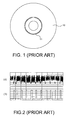
- a burst cutting area is provided on the optical disk for data writing so as to mark individual information on each optical disk.
- the BCA 11 of the optical disk 10 is positioned away from the disk center by 22.3 (+0/-0.4) mm to 23.50 ⁇ 0.5 mm.
- Each BCA data bit is encoded from two BCA channel bits.
- Channel bits "10" represent a data bit "0," while channel bits "01” represent a data bit “1.”
- a laser beam is employed to remove the reflection film on a portion of the BCA in a radiation direction.
- the length and gap of the removed reflection film is dominated by the RZ (Return to Zero) modulation of the channel bit.
- the RF (radio frequency) signal read by the optical head for the BCA data includes not only a BCA stripe signal but also a high-frequency pit string signal, as shown in FIG. 2(A).
- a BCA signal reproduction device is employed to process the RF signal and to generate the BCA reproducing signal, as shown in FIG. 2(B).
- FIG. 3 is a block diagram showing a conventional apparatus for retrieving the BCA signal.
- the BCA data bit retrieving device 30 utilizes a BCA channel bit generator 32 to sample the BCA reproducing signal based on a sampling clock.
- the BCA reproducing signal is then subjected to a RZ demodulation to become a BCA channel bit.
- the BCA decoder 33 decodes the BCA channel bit to generate a BCA data bit.
- One method for generating a sampling clock is to use a reference clock whose frequency is divided in the frequency divider 31. However, the method has to make sure that the disk rotating speed meets a predefined value. If the disk rotating speed deviates from the predefined value, the BCA channel bit generator 32 may not correctly sample the BCA reproducing signal based on the sampling clock because the frequency of the BCA reproducing signal changes with the variation of the disk rotating speed.
- an object of the invention is to provide a sampling clock generator for BCA data decoding using a FG signal (spindle motor speed indicating signal) of the spindle motor to generate a sampling clock.
- the sampling clock generator of the invention includes a frequency counter, a divider and a variable frequency divider.
- the frequency counter receives a FG signal, counts a number of pulses of a reference clock corresponding to each period of the FG signal, and generates a counting value.
- the divider receives the counting value of the frequency counter and divides the counting value by a predefined value to generate a divided value.
- the variable frequency divider receives the reference clock, a BCA reproducing signal and the divided value, divides the frequency of the reference clock using the divided value as a divisor of the variable frequency divider to generate the sampling clock, and adjusts the phase of the sampling clock based on the BCA reproducing signal.
- sampling clock generator for BCA data decoding of the invention will be described with reference to the accompanying drawings.
- FIG. 4 is a block diagram showing the implementation architecture of the sampling clock generator for BCA data decoding according to the invention.
- the sampling clock generator 41 for BCA data decoding of the invention receives a spindle-motor-speed indicating signal FG and a BCA reproducing signal to generate a sampling clock for BCA data decoding.
- the sampling clock is supplied to the BCA channel bit generator 42 and the BCA decoder 43. Therefore, the BCA channel bit generator 42 samples the correct BCA channel bit and the BCA decoder 43 decodes the correct BCA data bit based on the sampling clock.
- the BCA channel bit rate is 1/(8.89 ⁇ s) or 112.49 KHz at the disk rotating speed of 1440 rpm (24Hz). However, if the disk rotating speed deviates from 1440 rpm, the BCA channel bit rate will also deviate from 112.49 KHz. For example, the BCA channel bit rate is 1/(9.85 ⁇ s) or 101.55 KHz at a disk rotating speed of 1300 rpm (21.67 Hz).
- the BCA channel bit generator uses a sampling clock with a constant frequency to retrieve the BCA channel bit data, the BCA channel bit data may be correctly retrieved at a standard disk rotating speed. However, if the disk rotating speed deviates far from the standard disk rotating speed, the retrieved BCA channel bit data may be incorrect.
- the period of the spindle-motor-speed indicating signal FG is 1/(24 * N), wherein N is an integer, such as 3, 4, 6, and the like, depending on different spindle motor designs.
- a period of the spindle-motor-speed indicating signal FG has about 4678/N (i.e., 1/(24*N)/(8 .89* 10 -6 )) BCA channel bits. Since the BCA channel bit rate is directly proportional to the frequency of the spindle-motor-speed indicating signal FG, a sampling clock for BCA data decoding with a correct frequency can be provided as long as the frequency of the spindle-motor-speed indicating signal FG is computed based on the relationship of (4678/N).
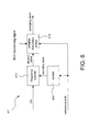
- FIG. 5 is a block diagram showing the sampling clock generator for BCA data decoding according to a first embodiment of the invention.
- the sampling clock generator 41 includes a frequency counter 411, a divider 412, and a variable frequency divider 413 with a variable divisor. Because the invention utilizes a reference clock as a standard clock to generate a sampling clock, the frequency of the reference clock has to be higher than that of the spindle-motor-speed indicating signal FG and that of the sampling clock. For example, the frequency of the reference clock may be 33 MHz.
- the frequency counter 411 receives the spindle-motor-speed indicating signal FG and the reference clock, and counts the number of pulses of the reference clock corresponding to each period of the spindle-motor-speed indicating signal FG to generate a counting value. For example, when the disk rotating speed is 1440 rpm and N is 4, the counting value is about 343.75 K.
- the divider 412 divides the counting value to scale down the counting value into a divided value.
- the divisor of the divider 412 is defined according to the relation of the frequency of the spindle-motor-speed indicating signal FG and the BCA channel bit rate, such as about 4678/N. For example, if N is 4, the divisor is about 1196.
- the divided value outputted from the divider 412 is about 287 in this embodiment.
- the variable frequency divider 413 divides the frequency of the reference clock according to the divided value to generate a sampling clock.
- the sampling clock has a frequency substantially equal to 115 KHz in this embodiment.
- the frequency of 115 KHz deviates from the required frequency 112.5KHz of the sampling clock by less than 5%. This frequency deviation of less than 5% can be compensated using the design of the variable frequency divider by adjusting the phase in order to prevent the channel bit from being incorrectly sampled.
- the frequency of the sampling clock obtained from the sampling clock generator of the invention changes proportionally to the frequency of the spindle-motor-speed indicating signal FG, because the frequency of the spindle-motor-speed indicating signal FG changes with the disk rotating speed.
- the counting value in this embodiment substantially becomes 381 K
- the divided value becomes 318
- the frequency of the sampling clock becomes 103.8 KHz. Consequently, the frequency of the sampling clock correspondingly decreases 10.3%, and then the system may generate a correct frequency of the sampling clock corresponding to the rotating speed.
- FIG. 6 is a block diagram showing the sampling clock generator for BCA data decoding according to a second embodiment of the invention.
- the sampling clock generator 41 utilizes the frequency counter to generate a counting value, which is then divided by a predefined value to become a divided value.
- the sampling clock generator 41' divides the frequency of the reference clock to generate a counting clock, and then utilizes a frequency counter to generate a divided value.
- the sampling clock generator 41' includes a frequency divider 414, a frequency counter 411, and a variable frequency divider 413 with a variable divisor.
- the frequency of the reference clock has to be higher than that of the spindle-motor-speed indicating signal FG and that of the sampling clock.
- the frequency of the reference clock may be 33 MHz.
- the sampling clock generator 41' utilizes the frequency divider 414 to divide the frequency of the reference clock and to generate a counting clock.
- the frequency divisor of the frequency divider 414 is defined according to relation of the frequency of the spindle-motor-speed indicating signal FG and the BCA channel bit rate, such as about 4678/N. In the second embodiment, for example, the divided value is 1196. Consequently, the frequency of the counting clock generated from the frequency divider 414 is 27.59 KHz.
- the frequency counter 411 receives the spindle-motor-speed indicating signal FG and counting clock, counts the number of pulses of the counting clock corresponding to each period of the spindle-motor-speed indicating signal FG, and generates a divided value accordingly. For example, when the disk rotating speed is 1440 rpm and N is 4, the divided value is about 287.
- the variable frequency divider 413 divides the frequency of the reference clock according to the divided value to generate a sampling clock.
- the sampling clock has a frequency substantially equal to 115 KHz in this embodiment. The frequency of 115 KHz in this embodiment deviates from the required frequency 112.5KHz of the sampling clock by less than 5%.
- This frequency deviation of less than 5% may be compensated using the design of the variable frequency divider by adjusting the phase to prevent the channel bit from being incorrectly sampled.
- the frequency divider 414 may be omitted.
- the frequency divider 414 can be omitted.
- FIG. 7 is a block diagram showing a variable frequency divider.
- the variable frequency divider 413 includes a clear signal generator 4131, a counter 4132, and a pulse generator 4133.
- the variable frequency divider 413 utilizes the BCA reproducing signal to adjust the phase of the sampling clock so that the generated sampling clock may have a better sampling phase and a minute frequency error in the sampling clock may also be compensated.
- the variable frequency divider 413 utilizes the clear signal generator 4131 to generate a clear signal according to the BCA reproducing signal. For example, a pulse of a clear signal may be generated at the rising edge of each BCA reproducing signal.
- the counter 4132 receives the reference clock and the divided value to generate a counting value.
- the counter 4132 is reset when the counting value equals to the divided value or when the pulse of the clear signal is received.
- the pulse generator 4133 receives the counting value of the counter 4132, and generates a pulse on the sampling clock when the counting value equals to "A.”
- the pulse width of the sampling clock may be designed according to the requirements. For example, the pulse generator 4133 may output a signal of HIGH when the counting value is between "A” and "A+B,” and output a signal of LOW when the counting value is not between "A” and "A+B.”
- FIG. 8 is a schematic illustration showing the relation of the BCA reproducing signal, counting value and sampling clock.
- the counting value is cleared and reset to 0 at the rising edge of the BCA reproducing signal.
- the sampling clock generates a pulse.
- the counting value is counted to "D" (D is a divided value)
- the counter is reset to 0 and recount. Since the variable frequency divider 413 utilizes the BCA reproducing signal to adjust the phase, the generation of the sampling clock will never be influenced even if some errors occur in the divided value.
Landscapes
- Engineering & Computer Science (AREA)
- Signal Processing (AREA)
- Signal Processing For Digital Recording And Reproducing (AREA)
Abstract
Description
- The invention relates generally to a sampling clock generator for BCA data decoding, and in particular to a sampling clock generator for BCA data decoding using a speed indicating signal of a spindle motor to generate a sampling clock.
- Currently, digital video optical disks or digital versatile disks (hereinafter referred to as DVDs) include DVD-ROM (Read Only Memory), DVD-R (Recordable), and DVD-RAM (Random Access Memory). In the development of DVD-ROM, a burst cutting area (BCA) is provided on the optical disk for data writing so as to mark individual information on each optical disk. As shown in FIG. 1, the
BCA 11 of theoptical disk 10 is positioned away from the disk center by 22.3 (+0/-0.4) mm to 23.50±0.5 mm. Each BCA data bit is encoded from two BCA channel bits. Channel bits "10" represent a data bit "0," while channel bits "01" represent a data bit "1." In the BCA data writing method, a laser beam is employed to remove the reflection film on a portion of the BCA in a radiation direction. The length and gap of the removed reflection film is dominated by the RZ (Return to Zero) modulation of the channel bit. Since a dummy pit string already exists in the original BCA, the RF (radio frequency) signal read by the optical head for the BCA data includes not only a BCA stripe signal but also a high-frequency pit string signal, as shown in FIG. 2(A). Thereafter, a BCA signal reproduction device is employed to process the RF signal and to generate the BCA reproducing signal, as shown in FIG. 2(B). - FIG. 3 is a block diagram showing a conventional apparatus for retrieving the BCA signal. As shown in FIG. 3, the BCA data
bit retrieving device 30 utilizes a BCAchannel bit generator 32 to sample the BCA reproducing signal based on a sampling clock. The BCA reproducing signal is then subjected to a RZ demodulation to become a BCA channel bit. Next, theBCA decoder 33 decodes the BCA channel bit to generate a BCA data bit. One method for generating a sampling clock is to use a reference clock whose frequency is divided in thefrequency divider 31. However, the method has to make sure that the disk rotating speed meets a predefined value. If the disk rotating speed deviates from the predefined value, the BCAchannel bit generator 32 may not correctly sample the BCA reproducing signal based on the sampling clock because the frequency of the BCA reproducing signal changes with the variation of the disk rotating speed. - Although a PLL (Phase Locked Loop) circuit may be employed to generate the sampling clock according to the BCA reproducing signal, the PLL circuit is complicated and expensive. In addition, U.S. Patent No. 6,034,934, entitled "DISC REPRODUCTION APPARATUS," also discloses a method for generating the sampling clock by calculating the edge interval. In such a method, however, additional firmware or circuitry is required, and the cost thereof is high accordingly.
- In view of the above-mentioned problems, an object of the invention is to provide a sampling clock generator for BCA data decoding using a FG signal (spindle motor speed indicating signal) of the spindle motor to generate a sampling clock.
- To achieve the above-mentioned object, the sampling clock generator of the invention includes a frequency counter, a divider and a variable frequency divider. The frequency counter receives a FG signal, counts a number of pulses of a reference clock corresponding to each period of the FG signal, and generates a counting value. The divider receives the counting value of the frequency counter and divides the counting value by a predefined value to generate a divided value. The variable frequency divider receives the reference clock, a BCA reproducing signal and the divided value, divides the frequency of the reference clock using the divided value as a divisor of the variable frequency divider to generate the sampling clock, and adjusts the phase of the sampling clock based on the BCA reproducing signal.
-
- FIG. 1 is a schematic illustration showing the BCA on an optical disk.
- FIG. 2(A) shows the RF signal acquired from the optical disk.
- FIG. 2(B) shows BCA reproducing signal generated using a BCA signal reproduction device to process the RF signal.
- FIG. 3 is a block diagram showing a conventional apparatus for retrieving the BCA signal.
- FIG. 4 is a block diagram showing the implementation architecture of the sampling clock generator for BCA data decoding according to the invention.
- FIG. 5 is a block diagram showing the sampling clock generator for BCA data decoding according to a first embodiment of the invention.
- FIG. 6 is a block diagram showing the sampling clock generator for BCA data decoding according to a second embodiment of the invention.
- FIG. 7 is a block diagram showing a variable frequency divider of the sampling clock generator for BCA data decoding according to the invention.
- FIG. 8 is a schematic illustration showing the relation of the BCA reproducing signal, counting value and sampling clock.
-
- The sampling clock generator for BCA data decoding of the invention will be described with reference to the accompanying drawings.
- FIG. 4 is a block diagram showing the implementation architecture of the sampling clock generator for BCA data decoding according to the invention. Referring to FIG. 4, the
sampling clock generator 41 for BCA data decoding of the invention receives a spindle-motor-speed indicating signal FG and a BCA reproducing signal to generate a sampling clock for BCA data decoding. The sampling clock is supplied to the BCAchannel bit generator 42 and theBCA decoder 43. Therefore, the BCAchannel bit generator 42 samples the correct BCA channel bit and theBCA decoder 43 decodes the correct BCA data bit based on the sampling clock. - According to the BCA specification, the BCA channel bit rate is 1/(8.89 µs) or 112.49 KHz at the disk rotating speed of 1440 rpm (24Hz). However, if the disk rotating speed deviates from 1440 rpm, the BCA channel bit rate will also deviate from 112.49 KHz. For example, the BCA channel bit rate is 1/(9.85 µs) or 101.55 KHz at a disk rotating speed of 1300 rpm (21.67 Hz). Hence, if the BCA channel bit generator uses a sampling clock with a constant frequency to retrieve the BCA channel bit data, the BCA channel bit data may be correctly retrieved at a standard disk rotating speed. However, if the disk rotating speed deviates far from the standard disk rotating speed, the retrieved BCA channel bit data may be incorrect.
- It is assumed that the period of the spindle-motor-speed indicating signal FG is 1/(24 * N), wherein N is an integer, such as 3, 4, 6, and the like, depending on different spindle motor designs. In this case, a period of the spindle-motor-speed indicating signal FG has about 4678/N (i.e., 1/(24*N)/(8 .89* 10-6)) BCA channel bits. Since the BCA channel bit rate is directly proportional to the frequency of the spindle-motor-speed indicating signal FG, a sampling clock for BCA data decoding with a correct frequency can be provided as long as the frequency of the spindle-motor-speed indicating signal FG is computed based on the relationship of (4678/N).
- FIG. 5 is a block diagram showing the sampling clock generator for BCA data decoding according to a first embodiment of the invention. The
sampling clock generator 41 includes afrequency counter 411, adivider 412, and avariable frequency divider 413 with a variable divisor. Because the invention utilizes a reference clock as a standard clock to generate a sampling clock, the frequency of the reference clock has to be higher than that of the spindle-motor-speed indicating signal FG and that of the sampling clock. For example, the frequency of the reference clock may be 33 MHz. First, thefrequency counter 411 receives the spindle-motor-speed indicating signal FG and the reference clock, and counts the number of pulses of the reference clock corresponding to each period of the spindle-motor-speed indicating signal FG to generate a counting value. For example, when the disk rotating speed is 1440 rpm and N is 4, the counting value is about 343.75 K. Next, thedivider 412 divides the counting value to scale down the counting value into a divided value. For example, the divisor of thedivider 412 is defined according to the relation of the frequency of the spindle-motor-speed indicating signal FG and the BCA channel bit rate, such as about 4678/N. For example, if N is 4, the divisor is about 1196. Consequently, the divided value outputted from thedivider 412 is about 287 in this embodiment. Finally, thevariable frequency divider 413 divides the frequency of the reference clock according to the divided value to generate a sampling clock. The sampling clock has a frequency substantially equal to 115 KHz in this embodiment. The frequency of 115 KHz deviates from the required frequency 112.5KHz of the sampling clock by less than 5%. This frequency deviation of less than 5% can be compensated using the design of the variable frequency divider by adjusting the phase in order to prevent the channel bit from being incorrectly sampled. - In addition, the frequency of the sampling clock obtained from the sampling clock generator of the invention changes proportionally to the frequency of the spindle-motor-speed indicating signal FG, because the frequency of the spindle-motor-speed indicating signal FG changes with the disk rotating speed. For example, when the disk rotating speed is decreased to 1300 rpm (the variation rate is 10.3%), the counting value in this embodiment substantially becomes 381 K, the divided value becomes 318, and the frequency of the sampling clock becomes 103.8 KHz. Consequently, the frequency of the sampling clock correspondingly decreases 10.3%, and then the system may generate a correct frequency of the sampling clock corresponding to the rotating speed.
- FIG. 6 is a block diagram showing the sampling clock generator for BCA data decoding according to a second embodiment of the invention. In the first embodiment, the
sampling clock generator 41 utilizes the frequency counter to generate a counting value, which is then divided by a predefined value to become a divided value. In the second embodiment, however, the sampling clock generator 41' divides the frequency of the reference clock to generate a counting clock, and then utilizes a frequency counter to generate a divided value. The sampling clock generator 41' includes afrequency divider 414, afrequency counter 411, and avariable frequency divider 413 with a variable divisor. Because the invention utilizes a reference clock as a standard clock to generate a sampling clock, the frequency of the reference clock has to be higher than that of the spindle-motor-speed indicating signal FG and that of the sampling clock. For example, the frequency of the reference clock may be 33 MHz. First, the sampling clock generator 41' utilizes thefrequency divider 414 to divide the frequency of the reference clock and to generate a counting clock. The frequency divisor of thefrequency divider 414 is defined according to relation of the frequency of the spindle-motor-speed indicating signal FG and the BCA channel bit rate, such as about 4678/N. In the second embodiment, for example, the divided value is 1196. Consequently, the frequency of the counting clock generated from thefrequency divider 414 is 27.59 KHz. Thereafter, thefrequency counter 411 receives the spindle-motor-speed indicating signal FG and counting clock, counts the number of pulses of the counting clock corresponding to each period of the spindle-motor-speed indicating signal FG, and generates a divided value accordingly. For example, when the disk rotating speed is 1440 rpm and N is 4, the divided value is about 287. Finally, thevariable frequency divider 413 divides the frequency of the reference clock according to the divided value to generate a sampling clock. The sampling clock has a frequency substantially equal to 115 KHz in this embodiment. The frequency of 115 KHz in this embodiment deviates from the required frequency 112.5KHz of the sampling clock by less than 5%. This frequency deviation of less than 5% may be compensated using the design of the variable frequency divider by adjusting the phase to prevent the channel bit from being incorrectly sampled. Of course, if the system provides a reference clock with two different frequencies, thefrequency divider 414 may be omitted. For example, if the system provides a counting clock and a reference clock whose frequency are integral multiples of the frequency of the counting clock, thefrequency divider 414 can be omitted. - FIG. 7 is a block diagram showing a variable frequency divider. Referring to FIG. 7, the
variable frequency divider 413 includes aclear signal generator 4131, acounter 4132, and apulse generator 4133. Thevariable frequency divider 413 utilizes the BCA reproducing signal to adjust the phase of the sampling clock so that the generated sampling clock may have a better sampling phase and a minute frequency error in the sampling clock may also be compensated. Thevariable frequency divider 413 utilizes theclear signal generator 4131 to generate a clear signal according to the BCA reproducing signal. For example, a pulse of a clear signal may be generated at the rising edge of each BCA reproducing signal. Thecounter 4132 receives the reference clock and the divided value to generate a counting value. Thecounter 4132 is reset when the counting value equals to the divided value or when the pulse of the clear signal is received. Thepulse generator 4133 receives the counting value of thecounter 4132, and generates a pulse on the sampling clock when the counting value equals to "A." The pulse width of the sampling clock may be designed according to the requirements. For example, thepulse generator 4133 may output a signal of HIGH when the counting value is between "A" and "A+B," and output a signal of LOW when the counting value is not between "A" and "A+B." - FIG. 8 is a schematic illustration showing the relation of the BCA reproducing signal, counting value and sampling clock. As shown in FIG. 8, the counting value is cleared and reset to 0 at the rising edge of the BCA reproducing signal. Then, when the counting value is "A," the sampling clock generates a pulse. Next, when the counting value is counted to "D" (D is a divided value), the counter is reset to 0 and recount. Since the
variable frequency divider 413 utilizes the BCA reproducing signal to adjust the phase, the generation of the sampling clock will never be influenced even if some errors occur in the divided value. - While certain exemplary embodiments have been described and shown in the accompanying drawings, it is to be understood that such embodiments are merely illustrative of and not restrictive on the broad invention, and that this invention should not be limited to the specific construction and arrangement shown and described, since various other modifications may occur to those ordinarily skilled in the art.
Claims (12)
- A sampling clock generator for BCA data decoding, comprising:a frequency counter for receiving a rotation speed indicating signal and a reference clock, counting a number of pulses of the reference clock corresponding to each period of the rotation speed indicating signal, and generating a first counting value;a divider for receiving the first counting value of the frequency counter, dividing the first counting value by a first predefined value, and generating a divided value; anda variable frequency divider for receiving the reference clock, a BCA reproducing signal and the divided value and generating a sampling clock by dividing frequency of the reference clock using the divided value as a divisor, the variable frequency divider also adjusting the phase of the sampling clock according to the BCA reproducing signal.
- The sampling clock generator according to claim 1, wherein the rotation speed indicating signal is generated by a spindle motor controller of an optical disk player.
- The sampling clock generator according to claim 1, wherein the variable frequency divider comprises:a clear signal generator for generating a clear signal according to the BCA reproducing signal;a counter for receiving the reference clock and the divided value, outputting a second counting value, and clearing the second counting value when the clear signal is enabled; anda pulse generator for receiving the second counting value and generating a sampling pulse on the sampling clock when the second counting value equals a predefined second value.
- The sampling clock generator according to claim 3, wherein the clear signal generator enables the clear signal for a period of time at a rising edge of the BCA reproducing signal.
- A sampling clock generator for BCA data decoding, comprising:a frequency divider for receiving a reference clock, dividing the reference clock by a first predefined value, and generating a counting clock;a frequency counter for receiving a rotation speed indicating signal, counting a number of pulses of the counting clock corresponding to each period of the rotation speed indicating signal, and generating a divided value; anda variable frequency divider for receiving the reference clock, a BCA reproducing signal and the divided value to generate a sampling clock by dividing frequency of the reference clock using the divided value as a divisor, the variable frequency divider also adjusting the phase of the sampling clock according to the BCA reproducing signal.
- The sampling clock generator according to claim 5, wherein the rotation speed indicating signal is generated by a spindle motor driver.
- The sampling clock generator according to claim 5, wherein the variable frequency divider comprises:a clear signal generator for generating a clear signal according to the BCA reproducing signal;a counter for receiving the reference clock and the divided value, outputting a counting value, and clearing the counting value when the clear signal is enabled; anda pulse generator for receiving the counting value and generating a sampling pulse on the sampling clock when the counting value equals to a second predefined value.
- The sampling clock generator according to claim 7, wherein the clear signal generator enables the clear signal for a period of time at a rising edge of the BCA reproducing signal.
- A sampling clock generator for BCA data decoding, comprising:a frequency counter for receiving a rotation speed indicating signal and a first reference clock, counting a number of pulses of the first reference clock corresponding to each period of the speed indicating signal, and outputting a divided value; anda variable frequency divider for receiving a second reference clock, a BCA reproducing signal and the divided value and generating a sampling clock by dividing frequency of the second reference clock using the divided value as a divisor and adjusting the phase of the sampling clock according to the BCA reproducing signal.
- The sampling clock generator according to claim 9, wherein the frequency of the first reference clock and the frequency of the second reference clock are positive integral multiples of a third reference clock.
- The sampling clock generator according to claim 9, wherein the divided value is a function of the number of pulses of the first reference clock corresponding to each period of the rotation speed indicating signal.
- The sampling clock generator according to claim 9, wherein the rotation speed indicating signal is generated by a spindle motor controller of an optical disk player.
Priority Applications (1)
| Application Number | Priority Date | Filing Date | Title |
|---|---|---|---|
| EP03001133.2A EP1439536B1 (en) | 2003-01-20 | 2003-01-20 | Sampling clock generation for BCA data decoding |
Applications Claiming Priority (1)
| Application Number | Priority Date | Filing Date | Title |
|---|---|---|---|
| EP03001133.2A EP1439536B1 (en) | 2003-01-20 | 2003-01-20 | Sampling clock generation for BCA data decoding |
Publications (2)
| Publication Number | Publication Date |
|---|---|
| EP1439536A1 true EP1439536A1 (en) | 2004-07-21 |
| EP1439536B1 EP1439536B1 (en) | 2015-07-29 |
Family
ID=32524162
Family Applications (1)
| Application Number | Title | Priority Date | Filing Date |
|---|---|---|---|
| EP03001133.2A Expired - Lifetime EP1439536B1 (en) | 2003-01-20 | 2003-01-20 | Sampling clock generation for BCA data decoding |
Country Status (1)
| Country | Link |
|---|---|
| EP (1) | EP1439536B1 (en) |
Citations (5)
| Publication number | Priority date | Publication date | Assignee | Title |
|---|---|---|---|---|
| EP0454955A1 (en) * | 1990-03-30 | 1991-11-06 | Mitsubishi Denki Kabushiki Kaisha | Sampling clock generating circuit |
| JPH1173648A (en) * | 1997-08-29 | 1999-03-16 | Toshiba Corp | Disk reproducing apparatus and disk reproducing method |
| US20010021144A1 (en) * | 1996-12-19 | 2001-09-13 | Matsushita Electric Industrial Co., Ltd. | Optical disk, method for recording and reproducing write-once information on and from optical disk, optical disk reproducing device, optical disk recording and reproducing device, device for recording write-once information on optical disk, and optical disk recording device |
| US20020057638A1 (en) | 2000-11-10 | 2002-05-16 | Sue-Hong Chou | Method and a control circuit for controlling a BCA clock to read a BCA data on an optical medium |
| US20030002410A1 (en) * | 2000-09-21 | 2003-01-02 | Sony Corporation | Disk-like recording medium, disk recording apparatus and disk recording method, and disk playback apparatus and disk playback method |
Family Cites Families (1)
| Publication number | Priority date | Publication date | Assignee | Title |
|---|---|---|---|---|
| TW467370U (en) * | 1999-12-07 | 2001-12-01 | Via Tech Inc | Reference clock generation circuit of the disk data pre-recording region |
-
2003
- 2003-01-20 EP EP03001133.2A patent/EP1439536B1/en not_active Expired - Lifetime
Patent Citations (5)
| Publication number | Priority date | Publication date | Assignee | Title |
|---|---|---|---|---|
| EP0454955A1 (en) * | 1990-03-30 | 1991-11-06 | Mitsubishi Denki Kabushiki Kaisha | Sampling clock generating circuit |
| US20010021144A1 (en) * | 1996-12-19 | 2001-09-13 | Matsushita Electric Industrial Co., Ltd. | Optical disk, method for recording and reproducing write-once information on and from optical disk, optical disk reproducing device, optical disk recording and reproducing device, device for recording write-once information on optical disk, and optical disk recording device |
| JPH1173648A (en) * | 1997-08-29 | 1999-03-16 | Toshiba Corp | Disk reproducing apparatus and disk reproducing method |
| US20030002410A1 (en) * | 2000-09-21 | 2003-01-02 | Sony Corporation | Disk-like recording medium, disk recording apparatus and disk recording method, and disk playback apparatus and disk playback method |
| US20020057638A1 (en) | 2000-11-10 | 2002-05-16 | Sue-Hong Chou | Method and a control circuit for controlling a BCA clock to read a BCA data on an optical medium |
Non-Patent Citations (1)
| Title |
|---|
| PATENT ABSTRACTS OF JAPAN vol. 1999, no. 08 30 June 1999 (1999-06-30) * |
Also Published As
| Publication number | Publication date |
|---|---|
| EP1439536B1 (en) | 2015-07-29 |
Similar Documents
| Publication | Publication Date | Title |
|---|---|---|
| US7006415B2 (en) | Sampling clock generator for BCA data decoding | |
| US6434091B1 (en) | Information record disc and information recording apparatus | |
| CA2022192C (en) | Optical disk recording/reproducing device | |
| US8014241B2 (en) | Information recording method and apparatus | |
| EP1168330A2 (en) | Optical disc drive, timing signal generator, and information recording and reproduction method | |
| US6700847B2 (en) | Recording/reproducing apparatus and method using accurate recording/reproducing clock signal | |
| US6914862B2 (en) | Device and method for calibrating linear velocity and track pitch for optical disc drive | |
| US7394748B2 (en) | Method and apparatus for optical disk recording capable of reducing settling time and generating an accurate channel clock signal | |
| KR100505634B1 (en) | Apparatus and method for detecting phase difference between phase reference and wobble signal | |
| US7145850B2 (en) | Optical disc recording apparatus and control method therefor | |
| EP1439536B1 (en) | Sampling clock generation for BCA data decoding | |
| CN100385388C (en) | Sampling clock generator for prerecorded zone signal | |
| EP1386319B1 (en) | Record carrier and apparatus for scanning the record carrier | |
| JP4598923B2 (en) | Optical disc recording apparatus and semiconductor integrated circuit thereof | |
| US20060181998A1 (en) | Method and apparatus for generating a sampling clock for a burst cutting area of an optical disc | |
| US20040190415A1 (en) | Recorded information evaluation method and device and information recording medium therefor | |
| KR100459704B1 (en) | Apparatus and method for compensating phase difference between phase reference and wobble signal on optical storage medium | |
| US20040264325A1 (en) | Optical disk apparatus and information recording apparatus | |
| US8064310B2 (en) | Optical disk recording device which detects pre-pit distribution and shifts recording position accordingly | |
| JPH11232763A (en) | Jitter measuring device | |
| US20050259550A1 (en) | Method and apparatus of accessing BCA data | |
| JPH0877715A (en) | Demodulator for digital recording / reproducing device | |
| JPH07111048A (en) | Digital disc player | |
| JP2009238290A (en) | Timing signal generator | |
| JP2006127697A (en) | Optical disc apparatus and servo system adjustment method |
Legal Events
| Date | Code | Title | Description |
|---|---|---|---|
| PUAI | Public reference made under article 153(3) epc to a published international application that has entered the european phase |
Free format text: ORIGINAL CODE: 0009012 |
|
| AK | Designated contracting states |
Kind code of ref document: A1 Designated state(s): AT BE BG CH CY CZ DE DK EE ES FI FR GB GR HU IE IT LI LU MC NL PT SE SI SK TR |
|
| AX | Request for extension of the european patent |
Extension state: AL LT LV MK RO |
|
| 17P | Request for examination filed |
Effective date: 20041117 |
|
| AKX | Designation fees paid |
Designated state(s): DE GB |
|
| R17C | First examination report despatched (corrected) |
Effective date: 20061206 |
|
| GRAP | Despatch of communication of intention to grant a patent |
Free format text: ORIGINAL CODE: EPIDOSNIGR1 |
|
| INTG | Intention to grant announced |
Effective date: 20150316 |
|
| GRAS | Grant fee paid |
Free format text: ORIGINAL CODE: EPIDOSNIGR3 |
|
| GRAA | (expected) grant |
Free format text: ORIGINAL CODE: 0009210 |
|
| AK | Designated contracting states |
Kind code of ref document: B1 Designated state(s): DE GB |
|
| REG | Reference to a national code |
Ref country code: GB Ref legal event code: FG4D |
|
| REG | Reference to a national code |
Ref country code: DE Ref legal event code: R096 Ref document number: 60347863 Country of ref document: DE |
|
| REG | Reference to a national code |
Ref country code: DE Ref legal event code: R097 Ref document number: 60347863 Country of ref document: DE |
|
| PLBE | No opposition filed within time limit |
Free format text: ORIGINAL CODE: 0009261 |
|
| STAA | Information on the status of an ep patent application or granted ep patent |
Free format text: STATUS: NO OPPOSITION FILED WITHIN TIME LIMIT |
|
| 26N | No opposition filed |
Effective date: 20160502 |
|
| PGFP | Annual fee paid to national office [announced via postgrant information from national office to epo] |
Ref country code: GB Payment date: 20180129 Year of fee payment: 16 Ref country code: DE Payment date: 20180129 Year of fee payment: 16 |
|
| REG | Reference to a national code |
Ref country code: DE Ref legal event code: R119 Ref document number: 60347863 Country of ref document: DE |
|
| GBPC | Gb: european patent ceased through non-payment of renewal fee |
Effective date: 20190120 |
|
| PG25 | Lapsed in a contracting state [announced via postgrant information from national office to epo] |
Ref country code: DE Free format text: LAPSE BECAUSE OF NON-PAYMENT OF DUE FEES Effective date: 20190801 |
|
| PG25 | Lapsed in a contracting state [announced via postgrant information from national office to epo] |
Ref country code: GB Free format text: LAPSE BECAUSE OF NON-PAYMENT OF DUE FEES Effective date: 20190120 |