EP1439379B1 - Powder and granular material weighing apparatus - Google Patents
Powder and granular material weighing apparatus Download PDFInfo
- Publication number
- EP1439379B1 EP1439379B1 EP02777900.8A EP02777900A EP1439379B1 EP 1439379 B1 EP1439379 B1 EP 1439379B1 EP 02777900 A EP02777900 A EP 02777900A EP 1439379 B1 EP1439379 B1 EP 1439379B1
- Authority
- EP
- European Patent Office
- Prior art keywords
- powdery
- granular
- weighing
- weighing apparatus
- hopper
- Prior art date
- Legal status (The legal status is an assumption and is not a legal conclusion. Google has not performed a legal analysis and makes no representation as to the accuracy of the status listed.)
- Expired - Lifetime
Links
Images




Classifications
-
- G—PHYSICS
- G01—MEASURING; TESTING
- G01G—WEIGHING
- G01G19/00—Weighing apparatus or methods adapted for special purposes not provided for in the preceding groups
- G01G19/387—Weighing apparatus or methods adapted for special purposes not provided for in the preceding groups for combinatorial weighing, i.e. selecting a combination of articles whose total weight or number is closest to a desired value
- G01G19/393—Weighing apparatus or methods adapted for special purposes not provided for in the preceding groups for combinatorial weighing, i.e. selecting a combination of articles whose total weight or number is closest to a desired value using two or more weighing units
-
- G—PHYSICS
- G01—MEASURING; TESTING
- G01G—WEIGHING
- G01G17/00—Apparatus for or methods of weighing material of special form or property
- G01G17/04—Apparatus for or methods of weighing material of special form or property for weighing fluids, e.g. gases, pastes
- G01G17/06—Apparatus for or methods of weighing material of special form or property for weighing fluids, e.g. gases, pastes having means for controlling the supply or discharge
-
- B—PERFORMING OPERATIONS; TRANSPORTING
- B29—WORKING OF PLASTICS; WORKING OF SUBSTANCES IN A PLASTIC STATE IN GENERAL
- B29B—PREPARATION OR PRETREATMENT OF THE MATERIAL TO BE SHAPED; MAKING GRANULES OR PREFORMS; RECOVERY OF PLASTICS OR OTHER CONSTITUENTS OF WASTE MATERIAL CONTAINING PLASTICS
- B29B7/00—Mixing; Kneading
- B29B7/02—Mixing; Kneading non-continuous, with mechanical mixing or kneading devices, i.e. batch type
- B29B7/22—Component parts, details or accessories; Auxiliary operations
- B29B7/24—Component parts, details or accessories; Auxiliary operations for feeding
-
- B—PERFORMING OPERATIONS; TRANSPORTING
- B29—WORKING OF PLASTICS; WORKING OF SUBSTANCES IN A PLASTIC STATE IN GENERAL
- B29B—PREPARATION OR PRETREATMENT OF THE MATERIAL TO BE SHAPED; MAKING GRANULES OR PREFORMS; RECOVERY OF PLASTICS OR OTHER CONSTITUENTS OF WASTE MATERIAL CONTAINING PLASTICS
- B29B7/00—Mixing; Kneading
- B29B7/30—Mixing; Kneading continuous, with mechanical mixing or kneading devices
- B29B7/58—Component parts, details or accessories; Auxiliary operations
- B29B7/60—Component parts, details or accessories; Auxiliary operations for feeding, e.g. end guides for the incoming material
Definitions
- the present invention relates to a powdery- or granular-material weighing apparatus, and more particularly to a powdery- or granular-material weighing apparatus in which charging of a powdery or granular material to a weighing portion is performed by charging in parts into a plurality of scale units constituting a combination weigher so that the weighing speed is increased.
- Fig. 12 represents the relationship of charging weight and charging flow rate with charging time in a two-stage charging system.
- a powdery or granular material is supplied to a weighing hopper at a large flow rate until the measurement of the weight of the powdery or granular material reaches about 90% of a target weight (100%) (large quantity charging), and subsequently the remaining 10% of the powdery or granular material is supplied to the weighing hopper at a small flow rate (small quantity charging), in order to increase the weighing speed.
- a stage-less system weighing apparatus In order to resolve the problems in the weighing apparatus of two-stage charging mode, a stage-less system weighing apparatus has been developed.
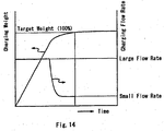
- Fig. 14 represents the relationship of charging weight and charging flow rate with charging time in the stage-less system.
- its charging flow rate is adjusted so as to decrease continuously from the large quantity charging to the small quantity charging according to a predetermined function so that overshoot does not occur at the switchover from the large quantity charging to the small quantity charging.
- a stage-less system weighing apparatus has a drawback in that a control for the stage-less shift from the large quantity charging to the small quantity charging is difficult, and for this reason, cost of the weighing apparatus increases.
- the time-consuming small quantity charging is essential to ensure weighing accuracy and therefore the weighing speed cannot be increased beyond a certain extent.
- the present invention resolves the foregoing problems, and an object of the present invention is to provide a weighing apparatus capable of weighing a powdery or granular material as a material to be weighed at high speed.
- EP-A-253895 , WO-A-8606161 , US-A-5319160 , US-A-4396078 are examples of documents relating to combination type weighing apparatus. Objects to be weighed in one or more of those documents include solid material, a powder material or a liquid material containing solid material.
- the present invention is such that a combination weigher, which has conventionally been used for weighing materials to be weighed that have essentially discontinuous value of weight, such as candies and potato chips, is applied to the weighing of powdery or granular materials, which have essentially continuous value of weight.
- a powdery- or granular-material weighing apparatus for weighing a powdery or granular material within a predetermined allowable range of a target weight, characterized by comprising a plurality of scale units each for weighing a powdery or granular material, the plurality of scale units constituting a combination weigher which discharges the weighed material from the scale units which constitute a combination that attains, among totals for arbitrary combinations of a predetermined number of weighed values in the scale units, a total that is within the predetermined allowable range of the target weight.
- each of the scale units is provided with a powdery- or granular-material supplying means for supplying the powdery or granular material to the scale units.
- the powdery-or granular-material supplying means is characterized by being a pinch valve.
- each of the scale units constitutes a combination weicher, so that a variation in the weights of the powdery or granular material charged in respective scale units does not cause a problem even if it occurs, and a variety of low-cost powdery- or granular-material supplying means can be adopted other than the feeders that are, as in conventional cases, capable of finely adjusting the charging quantity of a powdery or granular material.
- a weighing hopper for weighing a material to be weighed may comprise a cylindrical portion and a pinch valve for opening/closing a lower portion of the cylindrical portion, or may comprise a receiving container that receives the material to be weighed and flips upside down.
- a dust generation-preventing means for preventing the powdery or granular material from generating dust in between such constituting components as a feeding hopper for temporarily retaining the material to be weighed supplied from the powdery- or granular-material supplying means, a weighing hopper for weighing the material to be weighed, a collecting chute for collecting the weighed material discharged from each of the scale units and discharging it.
- the invention provides a powdery or granular-material weighing apparatus as set out in Claim 1.
- Fig. 1 is a schematic cross-sectional view showing a powdery- or granular-material weighing apparatus according to a first illustrative arrangement not falling within the scope of the claimed invention.
- the powdery- or granular-materiel weighing apparatus of the present arrangement has a configuration in which a plurality of the scale units 10 are provided around a center line C as the center. The same also applies to later-described arrangements and embodiments shown in Figs. 2 to 11 .
- the scale unit 10 in the present arrangement is provided with a cut gate 11 serving as a powdery or granular material-supplying means, and the cut gate 11 is attached to a lower portion of a powdery or granular material hopper 12 for guiding a powdery or granular material supplied from above to each of the scale units 10.
- a feeding hopper 13 serves the function of temporarily retaining the powdery or granular material supplied from the cut gate 11, and the cut gate 11 supplies the powdery or granular material to the feeding hopper 13, aiming at an individual target weight as the target for each of the scale units 10.
- the powdery or granular material supplied from the cut gate 11 to the feeding hopper 13 is supplied to a gate-type weighing hopper 14, which is positioned thereunder.
- the weighing hopper 14 is provided with a load cell 15 which measures the weight of the powdery or granular material within the weighing hopper 14, and the weighed value is sent to a control unit, which is not shown in the figure.
- a collecting chute 16 that collects the powdery or granular material discharged from each weighing hopper 14 and supplies it to a wrapping machine or the like.
- a dust-preventing bellow 18 is provided in between the following respective constituting components: the cut gate 11, the feeding hopper 13, the weighing hopper 14, and the collecting chute 16.
- the weighed value sent to the above-mentioned control unit is used for combinatorial computing along with the weighed values from the other scale units 10. Specifically, a predetermined number of the weighed values in the respective scale units is selected, the totals for those combinations are calculated, and among the totals, one that falls within a predetermined allowable range of a target weight is selected. Then the powdery or granular material, which is the material to be weighed, is discharged from the scale units that constitute this total to the above-mentioned collecting chute 16.
- a powdery or granular material is supplied from the cut gate 11 to the feeding hopper 13, aiming at the individual target weight for the scale unit 10 as the target, and during that time, the powdery or granular material is supplied to the feeding hopper 13 approximately at a constant flow rate without performing the large quantity charging and the small quantity charging, or similar controls, as in the conventional powdery- or granular-material weighing apparatus. Accordingly, the powdery or granular material is supplied to the weighing hopper 14 at high speed, and it is possible to increase the weighing speed of the powdery- or granular-material weighing apparatus as a whole.
- the powdery or granular material is simultaneously supplied to a plurality of the scale units 10. and because it is sufficient that the powdery or granular material be supplied aiming at the individual target weight, which is one part in several of the target weight, it becomes possible to reduce the feeding time of the powdery or granular material. Consequently, the weighing speed of the powdery- or granular-material weighing apparatus as a whole can be further increased. Further, with the powdery- or granular-material weighing apparatus of the present arrangement, assume that the powdery- or granular-material weighing apparatus of the present arrangement comprises, for example, 20 sets of the scale units 10.
- the powdery or granular material can be discharged from those scale units 10 that constitute the other combination while the powdery or granular material is being supplied to the weighing hoppers 14 of those scale units 10 from which the powdery or granular material have been discharged previously, which result in a increasing weighing speed of the powdery- or granular-material weighing apparatus as a whole.
- the feeding hopper 13 is provided between the cut gate 11 and the weighing hopper 14 in the present arrangement, it is possible to eliminate the feeding hopper 13 in cases where there is no leakage of the powdery or granular material from the cut gate 11.
- the present arrangement employs the gate-type weighing hopper 14, it is possible tc use a later-described pinch valve-type weighing hopper shown in Fig. 7 , a later-described container-flipping-type weighing hopper shown in Fig. 9 , and the like.
- Fig. 2 is a schematic cross-sectional view of a powdery-or granular-material weighing apparatus according to a second illustrative arrangement.
- Scale units 20 in the powdery- or granular-material weighing apparatus of the present arrangement are identical to the above-described scale unit 10 shown in Fig. 1 , except that a belt feeder 21 is used as a powdery-or granular-material supplying means in place of the cut gate 11 in the scale unit 10, and identical corresponding parts are denoted by the same reference numerals.
- a powdery or granular material is supplied from the belt feeder 21 to the feeding hopper 13 aiming at the individual target weight for each scale unit 20 as the target; and during that time, the powdery or granular material is supplied to the feeding hopper 13 approximately at a constant flow rate without performing the large quantity charging and the small quantity charging, or similar controls.
- the powdery or granular material is simultaneously supplied to a plurality of the scale units 20 and moreover it is sufficient that the powdery or granular material be supplied aiming at the individual target weight, which is one part in several of the target weight, it becomes possible to reduce the feeding time of the powdery or granular material.
- the powdery-or granular-material weighing apparatus of the present arrangement when there exist a plurality of such combinations of the scale units 20 that the total weight of each of the combinations falls within a predetermined allowable range of a target weight, as in the powdery- or granular-material weighing apparatus of Fig. 1 , it is possible to adopt a configuration in which the powdery or granular material is discharged from the scale units 20 that constitute another combination independently of the next supply of the powdery or granular material to the weighing hoppers 14.
- the feeding hopper 13 is likewise provided between the belt feeder 21 and the weighing hopper 14 in the present arrangement, it is possible to adopt a configuration in which the feeding hopper 13 is not provided in cases where there is no leakage of the powdery or granular material from the belt feeder 21.
- the present arrangement employs the gate-type weighing hopper 14, it is possible to use a later-described pinch valve-type weighing hopper shown in Fig. 7 , a later-described container-flipping-type weighing hopper shown in Fig. 9 , and the like.
- Fig. 3 is a schematic cross-sectional view of a powdery-or granular-material weighing apparatus according to a third illustrative arrangement.
- Scale units 30 in the powdery- or granular-material weighing apparatus of the present arrangement are identical to the above-described scale unit 10 shown in Fig. 1 , except that a disk feeder 31 is used as a powdery-or granular-material supplying means in place of the cut gate 11 in the scale unit 10 and that the feeding hopper 13 is not provided, and identical corresponding parts are denoted by the same reference rumerals.
- a powdery or granular-material weighing apparatus of the present arrangement a powdery or granular material is supplied to the weighing hopper 14 by rotating a scraper 31a of the disk feeder 31 and opening a discharging gate 31b.
- a powdery or granular material is supplied from the disk feeder 31 to the weighing hopper 14, aiming at the individual target weight for each scale unit 30 as the target, and during that time, the large quantity charging and the small quantity charging, or similar controls are not performed.
- the powdery or granular material is simultaneously supplied to a plurality of scale units 30 and moreover it is sufficient that the powdery or granular material be supplied aiming at the individual target weight, which is one part in several of the target weight, it becomes possible to reduce the feeding time of the powdery or granular material.
- the powdery- or granular-material weighing apparatus of the present arrangement when there exist a plurality of such combinations of the scale units 30 that their total weights fall within the predetermined allowable range of the target weight, as in the powdery- or granular-material weighing apparatus of Fig. 1 , it is possible to adopt a configuration in which the powdery or granular material is discharged from another combination of the scale units 30, independently of the next supply of the powdery or granular material to the weighing hopper 14.
- the feeding hopper 13 is not provided in the present arrangement, it is possible to provide the feeding hopper 13 may be provided between the disk feeder 31 and the weighing hopper 14 in cases where there is leakage of the powdery or granular material from the disk feeder 31.
- the present arrangement employs the gate-type weighing hopper 14, it is possible to use a later-described pinch valve-type weighing hopper shown in Fig. 7 , a later-described container-flipping-type weighing hopper shown in Fig. 9 , and the like.
- Fig. 4 is a schematic cross-sectional view of a powdery-or granular-material weighing apparatus according to a fourth illustrative arrangement.
- Scale units 40 in the powdery- or granular-material weighing apparatus of the present arrangement are identical to the above-described scale unit 10 shown in Fig. 1 , except that a screw feeder 41 is used as a powdery-or granular-material supplying means in place of the cut gate 11 in the scale unit 10, and identical corresponding parts are denoted by the same reference numerals.
- a powdery or granular material is supplied from the screw feeder 41 to the feeding hopper 13, aiming at the individual target weight for each scale unit 40 as the target, and during that time, the powdery or granular material is supplied to the feeding hopper 13 approximately at a constant flow rate without performing the large quantity charging and the small quantity charging, or similar controls.
- the powdery or granular material is simultaneously supplied to a plurality of the scale units 40 and moreover it is sufficient that the powdery or granular material be supplied aiming at the individual target weight, which is one part in several of the target weight, it becomes possible to reduce the feeding time of the powdery or granular material.
- the powdery- or granular-material weighing apparatus of the present arrangement when there exist a plurality of such combinations of the scale units 40 that their total weights fall within a predetermined allowable range of a target weight, as in the powdery- or granular-material weighing apparatus of Fig. 1 , it is possible to adopt a configuration in which the powdery or granular material is discharged from the scale units 40 that constitute another combination independently of the next supply of the powdery or granular material to the weighing hoppers 14.
- the feeding hopper 13 is provided between the screw feeder 41 and the weighing hopper 14 in the present arrangement, it is possible to adopt a configuration in which the feeding hopper 13 is not provided in cases where there is no leakage of the powdery or granular material from the screw feeder 41.
- the present arrangement employs the gate-type weighing hopper 14, it is possible to use a later-described pinch valve-type weighing hopper shown in Fig. 7 , a later-described container-flipping-type weighing hopper shown in Fig. 9 . and the like.
- Fig. 5 is a schematic cross-sectional view of a powdery-or granular-material weighing apparatus according to a fifth illustrative arrangement.
- Scale units 50 in the powdery- or granular-material weighing apparatus of the present arrangement are identical to the above-described scale unit 10 shown in Fig. 1 , except that a rotary feeder 51 is used as a powdery-or granular-material supplying means in place of the cut gate 11 in the scale unit 10, and identical corresponding parts are denoted by the same reference numerals.
- a powdery or granular material is supplied from the rotary feeder 51 to the feeding hopper 13, aiming at the individual target weight for each scale unit 50 as the target, approximately at a constant flow rate without performing the Large quantity charging and the small quantity charging, or similar controls.
- the powdery or granular material is simultaneously supplied to a plurality of the scale units 50 and moreover the powdery or granular material is supplied aiming at the individual target weight, which is one part in several of the target weight, it becomes possible to reduce the feeding time of the powdery or granular material.
- the powdery- or granular-material weighing apparatus of the present arrangement when there exist a plurality of such combinations of the scale units 50 that their total weights fall within a predetermined allowable range of a target weight, as in the powdery- or granular-material weighing apparatus of Fig. 1 , it is possible to adopt a configuration in which the powdery or granular material is discharged from the scale units 50 that constitute another combination independently of the next supply of the powdery or granular material to the weighing hoppers 14.
- the feeding hopper 13 is provided between the rotary feeder 51 and the weighing hopper 14 in the present arrangement, it is possible to adopt a configuration in which the feeding hopper 13 is not provided in cases where there is no leakage of the powdery or granular material from the rotary feeder 51.
- the present arrangement employs the gate-type weighing hopper 14, it is possible to use a later-described pinch valve-type weighing hopper shown in Fig. 7 , a later-described container-flipping-type weighing hopper shown in Fig. 9 , and the like.
- Fig. 6 is a schematic cross-sectional view of a powdery-or granular-material weighing apparatus according to a sixth illustrative arrangement.
- Scale units 60 in the powdery- or granular-material weighing apparatus of the present arrangement are identical to the above-described scale unit 10 shown in Fig. 1 except that an auger 61 is used as a powdery-or granular-material supplying means in place of the cut gate 11 in the scale unit 10, and identical corresponding parts are denoted by the same reference numerals.
- a powdery or granular material is supplied from the auger 61 to the feeding hopper 13, aiming at the individual target weight for each scale unit 60 as the target, at a constant flow rate without performing the large quantity charging and the small quantity charging, or similar controls.
- the powdery or granular material is simultaneously supplied to a plurality of the scale units 60 and moreover the powdery or granular material is supplied aiming at the individual target weight, which is one part in several of the target weight, it becomes possible to reduce the feeding time of the powdery or granular material.
- the powdery- or granular-material weighing apparatus of the present arrangement when there exist a plurality of such combinations of the scale units 60 that their total weights fall within a predetermined allowable range of a target weight, as in the powdery- or granular-material weighing apparatus of Fig. 1 , it is possible to adopt a configuration in which the powdery or granular material is discharged from the scale units 60 that constitute another combination independently of the next supply of the powdery or granular material to the weighing hoppers 14.
- the feeding hopper 13 is provided between the auger 61 and the weighing hopper 14 in the present arrangement, it is possible to adopt a configuration in which the feeding hopper 13 is not provided in cases where there is no leakage of the powdery or granular material from the auger 61.
- the present arrangement employs the gate-type weighing hopper 14, it is possible to use a later-described pinch valve-type weighing hopper shown in Fig. 7 , a later-described container-flipping-type weighing hopper shown in Fig. 9 , and the like.
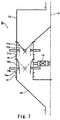
- Fig. 7 is a schematic cross-sectional view of a powdery- or granular-material weighing apparatus according to a first embodiment of the present invention.
- a scale units 70 in the powdery- or granular-material weighing apparatus of the present embodiment is furnished with a cylindrical portion 71a attached to a lower portion of a powdery- or granular-material hopper 12, and a pinch valve 71b for opening/closing a lower portion of the cylindrical portion 71a and serving as a powdery or granular material-supplying means.
- the cylindrical portion 71a and the pinch valve 71b are mounted inside a stationary cylinder 71c.
- the powdery- or granular-material weighing apparatus of the present embodiment is also furnished with a cylindrical portion 74a and a pinch valve 74b for opening/closing a lower portion of the cylindrical portion 74a.
- the cylindrical portion 74a and the pinch valve 74b are mounted inside a stationary cylinder 74c.
- a weighing hopper is constituted by the cylindrical portion 74a and the pinch valve 74b.
- a load cell 15 for measuring the weight of the powdery or granular material in the cylindrical portion 74a is attached outwardly of the stationary cylinder 74c. It should be noted that no feeding hopper is provided in the present embodiment.
- a collecting chute 16 Furnished below the cylindrical portion 74a is a collecting chute 16 for collecting the powdery or granular material discharge from each cylindrical portion 74a and supplying it to a wrapping machine or the like. Further, in the present embodiment, dust-preventing bellows 18 are provided in between the following respective constituting components: the stationary cylinder 71c, the stationary cylinder 74c, and the collecting chute 16.
- a powdery or granular material is supplied from the cylindrical portion 71a to the cylindrical portion 74a by opening the pinch valve 71b, aiming at the individual target weight for each scale unit 70 as the target, approximately at a constant flow rate without performing the large quantity charging and the small quantity charging, or similar controls.
- the powdery or granular material is simultaneously supplied to a plurality of the scale units 70 and moreover the powdery or granular material is supplied aiming at the individual target weight, which is one part in several of the target weight, it becomes possible to reduce the feeding time of the powdery or granular material.
- the powdery- or granular-material weighing apparatus of the present embodiment when there exist a plurality of such combinations of the scale units 70 that their total weights fall within a predetermined allowable range of a target weight, as in the powdery- or granular-material weighing apparatus of Fig. 1 , it is possible to adopt a configuration in which the powdery or granular material is discharged from the scale units 70 that constitute another combination independently of the next supply of the powdery or granular material to the cylindrical portions 74a.
- a feeding hopper is not provided in the present embodiment, it is possible to provide a feeding hopper between the cylindrical portion 71a and the cylindrical portion 74a in cases where there is leakage of the powdery or granular material from the cylindrical portion 71a.
- the present embodiment employs the pinch-valve type weighing hopper, it is possible to use a gate-type weighing hopper as shown in Fig. 1 , a later-described container-flipping-type weighing hopper as shown in Fig. 9 , and the like.
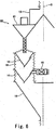
- Fig. 8 is a schematic cross-sectional view of a powdery- or granular-material weighing apparatus according to a seventh illustrative arrangement.
- Scale units 80 in the powdery- or granular-material weighing apparatus of the present arrangement are identical to the above-described scale unit 70 illustrated in Fig. 7 , except that a wing feeder 81 is used as a powdery- or granular-material supplying means in place of the cylindrical portion 71a, the pinch valve 71b, and the stationary cylinder 71c in the scale unit 70, and identical corresponding parts are denoted by the same reference numerals.
- a powdery or granular material is supplied to the cylindrical portion 74a by rotation of the wing feeder 81, aiming at the individual target weight for each scale unit 80 as the target, and during that time, the powdery or granular material is supplied approximately at a constant flow rate without performing the large quantity charging and the small quantity charging, or similar controls.
- the powdery or granular material is simultaneously supplied to a plurality of the scale units 80 and moreover it is sufficient that the powdery or granular material be supplied aiming at the individual target weight, which is one part in several of the target weights, it becomes possible to reduce the feeding time of the powdery or granular material.
- the powdery- or granular-material weighing apparatus of the present arrangement when there exist a plurality of such combinations of the scale units 80 that their total weights fall within a predetermined allowable range of a target weight, as in the powdery- or granular-material weighing apparatus of Fig. 1 , it is also possible to adopt a configuration in which the powdery or granular material is discharged from the scale units 80 that constitute another combination independently of the next supply of the powdery or granular material to the cylindrical portions 74a.
- a feeding hopper is not provided in the present arrangement, it is possible to provide a feeding hopper between the wing feeder 81 and the cylindrical portion 74a in cases where there is leakage of the powdery or granular material from the wing feeder 81.
- the present arrangement employs the pinch-valve type weighing hopper, it is possible to use a gate-type weighing hopper as shown in Fig. 1 , a later-described container-flipping-type weighing hopper as shown in Fig. 9 , and the like.
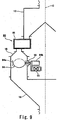
- FIG. 9 is a schematic cross-sectional view of a powdery- or granular-material weighing apparatus according to an eighth illustrative arrangement.
- a scale unit 90 in the powdery- or granular-material weighing apparatus of the present arrangement is provided with a slat valve 91 attached to a lower portion of the powdery or granular material hopper 12 and serving as a powdery- or granular-material supplying means, and a container-flipping-type weighing device 94 serving as a weighing hopper.
- the container-flipping-type weighing device 94 has a container portion 94a for receiving a powdery or granular material, and a flipping motor 94b that flips over the container portion 94a upside down.
- the container portion 94a and the flipping motor 94b are supported by the load cell 15 and are configured so that the weight of the powdery or granular material within the container portion 94a can be measured.
- Dust-preventing bellows 18 are provided in between the slat valve 91 and the container-flipping-type weighing device 94, and at a connecting portion between the container portion 94a and the flipping motor 94b.
- a collecting chute 16 for collecting the powdery or granular material discharged from each of the container-flipping-type weighing devices 94 and for supplying a wrapping machine or the like.
- a powdery or granular material is supplied to the container portion 94a of the container-flipping-type weighing device 94 by the slat valve 91, aiming at the individual target weight for each scale unit 90 as the target, and during that time, the powdery or granular material is supplied approximately at a constant flow rate without performing the Large quantity charging and the small quantity charging, or similar controls.
- the powdery or granular material is simultaneously supplied to a plurality of the scale units 90 and moreover it is sufficient that the powdery or granular material be supplied aiming at the individual target weight, which is one part in several of the target weight, it becomes possible to reduce the feeding time of the powdery or granular material.
- the powdery- or granular-material weighing apparatus of the present arrangement too, when there exist a plurality of such combinations of the scale units 90 that their total weights fall within a predetermined allowable range of a target weight, as in the powdery- or granular-material weighing apparatus of Fig. 1 , it is also possible to adopt a configuration in which the powdery or granular material is discharged from the scale units 90 that constitute another combination independently of the next supply of the powdery or granular material to the container-flipping-type weighing device 94.
- a feeding hopper is not provided in the present arrangement, it is possible to provide a feeding hopper between the cylindrical portion 71a and the cylindrical portion 74a in cases where there is leakage of the powdery or granular material from the slat valve 91.
- the present arrangement employs the container-flipping-type weighing hopper, it is possible to use a gate-type weighing hopper as shown in Fig. 1 , a pinch valve-type weighing hopper as shown in Fig. 7 , and the like.
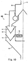
- Fig. 10 is a schematic cross-sectional view of a powdery- or granular-material weighing apparatus according to a ninth illustrative arrangement.
- Scale units 100 in the powdery- or granular-material weighing apparatus of the present arrangement are identical to the above-described scale unit 10 shown in Fig. 1 , except that a roll feeder 101 is used as a powdery- or granular-material supplying means in place of the cut gate 11 in the scale unit 10, and identical corresponding parts are denoted by the same reference numerals.
- a powdery or granular material is supplied from the roll feeder 101 to the feeding hopper 13 approximately at a constant flow rate without performing the large quantity charging and the small quantity charging, or similar controls, aiming at the individual target weight for each scale unit 100 as the target.
- the powdery or granular material is simultaneously supplied to a plurality of the scale units 100 and moreover the powdery or granular material is supplied aiming at the individual target weight, which is one part in several of the target weight, it becomes possible to reduce the feeding time of the powdery or granular material.
- the powdery- or granular-material weighing apparatus of the present arrangement when there exist a plurality of such combinations of the scale units 100 that their total weights fall within a predetermined allowable range of a target weight, as in the powdery- or granular-material weighing apparatus of Fig. 1 , it is also possible to adopt a configuration in which the powdery or granular material is discharged from the scale units 100 that constitute another combination independently of the next supply of the powder or granular material to the weighing hoppers 14.
- the feeding hopper 13 is provided between the roll feeder 101 and the weighing hopper 14 in the present arrangement, it is possible to adopt a configuration in which the feeding hopper 13 is not provided, in cases where there is no leakage of the powdery or granular material from the roll feeder 101.
- the present arrangement employs the gate-type weighing hopper 14, it is possible to use the previously-described pinch valve-type weighing hopper shown in Fig. 7 , the previously-described container-flipping-type weighing hopper shown in Fig. 9 , and the like.
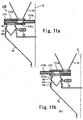
- FIG. 11a and Fig. 11b are schematic cross-sectional views of a powdery- or granular-material weighing apparatus according to a ninth illustrative arrangement.
- a scale unit 110 in the powdery- or granular-material weighing apparatus of the present arrangement is provided with a volumetric feeder 111 attached to a lower portion of the powdery or granular material hopper 12 and serving as a powdery- or granular-material supplying means, and is not provided with a feeding hopper.
- the volumetric feeder 111 has a stationary portion 111a that is fixed to the powdery or granular material hopper 12 and the weighing hopper 14, and a movable portion 111b that slides within the stationary portion 111a, and the movable portion 111b is provided with a weighing hole 111c.
- a powdery or granular material is supplied into the weighing hole 111c in a state in which the weighing hole 111c of the movable portion 111b is located under the powdery or granular material hopper 12, and next, when the movable portion 111b shifts and accordingly the weighing hole 111c reaches a position above the weighing hopper 14 as illustrated in Fig.
- the powdery or granular material is supplied to the weighing hopper 14.
- the powdery or granular material is supplied from the powdery or granular material hopper 12 to the weighing hopper 14.
- a powdery or granular material is supplied from the volumetric feeder 111 to the weighing hopper 14 approximately at a constant quantity, aiming at the individual target weight for each scale unit 110 as the target.
- the powdery or granular material is simultaneously supplied to a plurality of the scale units 110, it becomes possible to reduce the feeding time of the powdery or granular material.
- the powdery- or granular-material weighing apparatus of the present arrangement too, when there exist a plurality of such combinations of the scale units 110 that their total weights fall within a predetermined allowable range of a target weight, as in the powdery- or granular-material weighing apparatus of Fig. 1 , it is also possible to adopt a configuration in which the powdery or granular material is discharged from the scale units 110 that constitute another combination independently of the next supply of the powder or granular material to the volumetric feeder 111.
- a feeding hopper is not provided in the present arrangement, it is possible to provide a feeding hopper between the volumetric feeder 111 and the weighing hopper 14 in cases where there is leakage of the powdery or granular material from the volumetric feeder 111.
- the present arrangement employs a gate-type weighing hopper, it is possible to use the valve-type weighing hopper shown in Fig. 7 , the container-flipping-type weighing hopper shown in Fig. 9 , and the like.
- the weighing speed of the respective powdery- or granular-material weighing apparatuses according to the foregoing embodiment was compared with that of a conventional powdery- or granular-material weighing apparatus, the conventional powdery- or granular-material weighing apparatus as shown in Fig. 12 to Fig. 14 showed a weighing speed of about 12 to 15 bags/minute, but the powdery- or granular-material weighing apparatuses of the present invention shown in Fig. 7 , which make use of a combination weigher, made a high-speed weighing at about 80 bags/minute possible.
- the powdery- or granular-material weighing apparatus of the present invention since the powdery or granular material is supplied aimong at an individual target weight for a scale unit, which is one part in several of a target weight, is simultaneously charged into respective feeding hoppers or respective weighing hoppers, the charging time of the powdery or granular material can be reduced. Moreover, because a large quantity charging or a small quantity charging, or similar such controls as have been conventionally necessary are unnecessary in supplying the powdery or granular material, a high-speed weighing for powdery or granular materials can be carried out at low cost.
- the powdery or granular material can be discharged from the scale units that constitute another combination independently of the next supply of the powdery or granular material to the weighing hoppers, so that it is possible to attain a further improvement in the weighing speed.
Landscapes
- Physics & Mathematics (AREA)
- General Physics & Mathematics (AREA)
- Weight Measurement For Supplying Or Discharging Of Specified Amounts Of Material (AREA)
- Filling Or Emptying Of Bunkers, Hoppers, And Tanks (AREA)
Description
- The present invention relates to a powdery- or granular-material weighing apparatus, and more particularly to a powdery- or granular-material weighing apparatus in which charging of a powdery or granular material to a weighing portion is performed by charging in parts into a plurality of scale units constituting a combination weigher so that the weighing speed is increased.
- Conventionally, two-stage charging system weighing apparatuses have been used for weighing powder or granular materials to improve weighing speed and increase weighing accuracy.
Fig. 12 represents the relationship of charging weight and charging flow rate with charging time in a two-stage charging system. As shown inFig. 12 , in the two-stage charging system weighing apparatus, a powdery or granular material is supplied to a weighing hopper at a large flow rate until the measurement of the weight of the powdery or granular material reaches about 90% of a target weight (100%) (large quantity charging), and subsequently the remaining 10% of the powdery or granular material is supplied to the weighing hopper at a small flow rate (small quantity charging), in order to increase the weighing speed. - With such a weighing apparatus of a two-stage charging mode, conceivable methods for further increasing the weighing speed while maintaining its weighing accuracy are as follows: (1) the charging weight in the large quantity charging is further increased, for example, to 97% from about 90% as described above; or (2) the quantity of flow of a material to be weighed is increased in the large quantity charging. However, in the foregoing method (1), in which the charging weight in the large quantity charging is increased, overshoot occurs when the flow rate changes at the switchover from the large quantity charging to the small quantity charging, as shown in
Fig. 13 , resulting in a situation in which the target weight is assumed to be reached and the small quantity charging is not carried out. In this case, the weighed value obtained finally will be less than the target weight. Likewise, in the foregoing method (2), in which the flow rate in the large quantity charging is increased, overshoot also occurs when the flow rate changes at the switchover from the large quantity charging to the small quantity charging, resulting in a situation in which the weighed values obtained finally will be less than the target weight. Further, there is a drawback in that a control for the switchover from the large quantity charging to the small quantity charging is necessary, which increases the cost of the weighing apparatus. In addition, in order to ensure weighing accuracy, it is essential to carry out the small quantity charging,
which is time-consuming, and the weighing speed cannot be increased beyond a certain level, which is another problem. - In order to resolve the problems in the weighing apparatus of two-stage charging mode, a stage-less system weighing apparatus has been developed.
Fig. 14 represents the relationship of charging weight and charging flow rate with charging time in the stage-less system. In the stage-less system, its charging flow rate is adjusted so as to decrease continuously from the large quantity charging to the small quantity charging according to a predetermined function so that overshoot does not occur at the switchover from the large quantity charging to the small quantity charging. However, such a stage-less system weighing apparatus has a drawback in that a control for the stage-less shift from the large quantity charging to the small quantity charging is difficult, and for this reason, cost of the weighing apparatus increases. Also as in the foregoing case of the two-stage charging mode, there is such a problem that the time-consuming small quantity charging is essential to ensure weighing accuracy and therefore the weighing speed cannot be increased beyond a certain extent. - The present invention resolves the foregoing problems, and an object of the present invention is to provide a weighing apparatus capable of weighing a powdery or granular material as a material to be weighed at high speed.
-
EP-A-253895 WO-A-8606161 US-A-5319160 ,US-A-4396078 are examples of documents relating to combination type weighing apparatus. Objects to be weighed in one or more of those documents include solid material, a powder material or a liquid material containing solid material. - The present invention is such that a combination weigher, which has conventionally been used for weighing materials to be weighed that have essentially discontinuous value of weight, such as candies and potato chips, is applied to the weighing of powdery or granular materials, which have essentially continuous value of weight. Specifically, a powdery- or granular-material weighing apparatus according to the present invention is for weighing a powdery or granular material within a predetermined allowable range of a target weight, characterized by comprising a plurality of scale units each for weighing a powdery or granular material, the plurality of scale units constituting a combination weigher which discharges the weighed material from the scale units which constitute a combination that attains, among totals for arbitrary combinations of a predetermined number of weighed values in the scale units, a total that is within the predetermined allowable range of the target weight.
- By making use of a combination weigher for powdery or granular materials, which essentially have continuous weighed values, it becomes unnecessary to carry out the small quantity charging in supplying a powdery or granular material to the scale units, so that the weighing speed can be improved considerably. Inaddition, Because the powdery or granular material that equates to a target weight of the entire scale can be charged in parts into a plurality of scale units, and moreover, the charging of the powdery or granular material can be performed simultaneously to each of the scale units, the weighing speed can be also improved. Furthermore, it becomes unnecessary to carry out the switchover from the large quantity charging to the small quantity charging, eliminating the need for a control device therefor, and thus, it becomes possible to reduce the cost of the scale.
- In a powdery- or granular-material weighing apparatus of the present invention, each of the scale units is provided with a powdery- or granular-material supplying means for supplying the powdery or granular material to the scale units. The powdery-or granular-material supplying means is characterized by being a pinch valve.
- In, a powdery- or granular-material weighing apparatus of the present invention, each of the scale units constitutes a combination weicher, so that a variation in the weights of the powdery or granular material charged in respective scale units does not cause a problem even if it occurs, and a variety of low-cost powdery- or granular-material supplying means can be adopted other than the feeders that are, as in conventional cases, capable of finely adjusting the charging quantity of a powdery or granular material.
- In addiction, a weighing hopper for weighing a material to be weighed may comprise a cylindrical portion and a pinch valve for opening/closing a lower portion of the cylindrical portion, or may comprise a receiving container that receives the material to be weighed and flips upside down. By adopting a weighing hopper with such a configuration, it is possible to prevent leakage of the powdery or granular material from the gate, which is caused by the use of the gate used in the conventional combination weigher, in the case where the powdery or granular material is a fine powdery material with a high flowability.
- In a powdery- or granular-material weighing apparatus of the present invention, which deals with a powdery or granular material as a material to be weighed, dust generation of powdery or granular material may cause a problem. In such cases, it is preferable to provide a dust generation-preventing means for preventing the powdery or granular material from generating dust in between such constituting components as a feeding hopper for temporarily retaining the material to be weighed supplied from the powdery- or granular-material supplying means, a weighing hopper for weighing the material to be weighed, a collecting chute for collecting the weighed material discharged from each of the scale units and discharging it.
- The invention provides a powdery or granular-material weighing apparatus as set out in Claim 1.
-
-
Fig. 1 is a schematic cross-sectional view of a powdery- or granular-material weighing apparatus according to a first illustrative arrangement; -
Fig. 2 is a schematic cross-sectional view of a powdery-or granular-material weighing apparatus according to a second illustrative arrangement; -
Fig. 3 is a schematic cross-sectional view of a powdery-or granular-material weighing apparatus according to a third illustrative arrangement; -
Fig. 4 is a schematic cross-sectional view of a powdery-or granular-material weighing apparatus according to a fourth illustrative arrangement; -
Fig. 5 is a schematic cross-sectional view of a powdery-or granular-material weighing apparatus according to a fifth illustrative arrangement; -
Fig. 6 is a schematic cross-sectional view of a powdery-or granular-material weighing apparatus according to a sixth illustrative arrangement; -
Fig. 7 is a schematic cross-sectional view of a powdery-or granular-material weighing apparatus according to a first embodiment of the present invention; -
Fig. 8 is a schematic cross-sectional view of a powdery-or granular-material weighing apparatus according to a seventh illustrative arrangement; -
Fig. 9 is a schematic cross-sectional view of a powdery-or granular-material weighing apparatus according to an eighth illustrative arrangement; -
Fig. 10 is a schematic cross-sectional view of a powdery-or granular-material weighing apparatus according to a ninth illustrative arrangement; -
Fig. 11a and 11b are schematic cross-sectional views of a powdery- or granular-material weighing apparatus according to a trenth illustrative arrangement; -
Fig. 12 is a graph representing the relationship of charging weight and charging flow rate with charging time in a conventional two-stage charging system; -
Fig. 13 is a graph representing an overshoot that occurs in a conventional powdery- or granular-material weighing apparatus; and -
Fig. 14 is a graph representing the relationship of charging weight and charging flow rate with charging time in a conventional stage-less system. - Hereinafter, preferred embodiments of the present invention are described with reference to the drawings.
Fig. 1 is a schematic cross-sectional view showing a powdery- or granular-material weighing apparatus according to a first illustrative arrangement not falling within the scope of the claimed invention. Although the figure illustrates the cross section of only one ofscale units 10 that constitute the powdery- or granular-material weighing apparatus, the powdery- or granular-materiel weighing apparatus of the present arrangement has a configuration in which a plurality of thescale units 10 are provided around a center line C as the center. The same also applies to later-described arrangements and embodiments shown inFigs. 2 to 11 . - The
scale unit 10 in the present arrangement is provided with acut gate 11 serving as a powdery or granular material-supplying means, and thecut gate 11 is attached to a lower portion of a powdery orgranular material hopper 12 for guiding a powdery or granular material supplied from above to each of thescale units 10. By pivoting thecut gate 11 around an opening/closing center 11a, the powdery or granular material is supplied to afeeding hopper 13. Thefeeding hopper 13 serves the function of temporarily retaining the powdery or granular material supplied from thecut gate 11, and thecut gate 11 supplies the powdery or granular material to thefeeding hopper 13, aiming at an individual target weight as the target for each of thescale units 10. The powdery or granular material supplied from thecut gate 11 to thefeeding hopper 13 is supplied to a gate-type weighing hopper 14, which is positioned thereunder. The weighinghopper 14 is provided with aload cell 15 which measures the weight of the powdery or granular material within the weighinghopper 14, and the weighed value is sent to a control unit, which is not shown in the figure. Provided below the weighinghopper 14 is acollecting chute 16 that collects the powdery or granular material discharged from each weighinghopper 14 and supplies it to a wrapping machine or the like. In addition, in the present arrangement, a dust-preventingbellow 18 is provided in between the following respective constituting components: thecut gate 11, thefeeding hopper 13, theweighing hopper 14, and thecollecting chute 16. - In the powdery- or granular-material weighing apparatus of the present arrangement, the weighed value sent to the above-mentioned control unit is used for combinatorial computing along with the weighed values from the
other scale units 10. Specifically, a predetermined number of the weighed values in the respective scale units is selected, the totals for those combinations are calculated, and among the totals, one that falls within a predetermined allowable range of a target weight is selected. Then the powdery or granular material, which is the material to be weighed, is discharged from the scale units that constitute this total to the above-mentionedcollecting chute 16. - In the powdery- or granular-material weighing apparatus of the present arrangement, a powdery or granular material is supplied from the
cut gate 11 to thefeeding hopper 13, aiming at the individual target weight for thescale unit 10 as the target, and during that time, the powdery or granular material is supplied to thefeeding hopper 13 approximately at a constant flow rate without performing the large quantity charging and the small quantity charging, or similar controls, as in the conventional powdery- or granular-material weighing apparatus. Accordingly, the powdery or granular material is supplied to the weighinghopper 14 at high speed, and it is possible to increase the weighing speed of the powdery- or granular-material weighing apparatus as a whole. Moreover, because the powdery or granular material is simultaneously supplied to a plurality of thescale units 10. and because it is sufficient that the powdery or granular material be supplied aiming at the individual target weight, which is one part in several of the target weight, it becomes possible to reduce the feeding time of the powdery or granular material. Consequently, the weighing speed of the powdery- or granular-material weighing apparatus as a whole can be further increased. Further, with the powdery- or granular-material weighing apparatus of the present arrangement, assume that the powdery- or granular-material weighing apparatus of the present arrangement comprises, for example, 20 sets of thescale units 10. After a target weight within a predetermined allowable range has been initially attained by, for example, 4 sets of thescale units 10, if there still exist another combination of thescale units 10 that attains a total weight within the predetermined allowable range of the target weight among the remaining 16 sets of thescale units 10, the powdery or granular material can be discharged from thosescale units 10 that constitute the other combination while the powdery or granular material is being supplied to the weighinghoppers 14 of thosescale units 10 from which the powdery or granular material have been discharged previously, which result in a increasing weighing speed of the powdery- or granular-material weighing apparatus as a whole. - It should be noted that although the
feeding hopper 13 is provided between thecut gate 11 and the weighinghopper 14 in the present arrangement, it is possible to eliminate thefeeding hopper 13 in cases where there is no leakage of the powdery or granular material from thecut gate 11. In addition, although the present arrangement employs the gate-type weighing hopper 14, it is possible tc use a later-described pinch valve-type weighing hopper shown inFig. 7 , a later-described container-flipping-type weighing hopper shown inFig. 9 , and the like. -
Fig. 2 is a schematic cross-sectional view of a powdery-or granular-material weighing apparatus according to a second illustrative arrangement.Scale units 20 in the powdery- or granular-material weighing apparatus of the present arrangement are identical to the above-describedscale unit 10 shown inFig. 1 , except that abelt feeder 21 is used as a powdery-or granular-material supplying means in place of thecut gate 11 in thescale unit 10, and identical corresponding parts are denoted by the same reference numerals. - In the powdery- or granular-material weighing apparatus of the present arrangement as well, a powdery or granular material is supplied from the
belt feeder 21 to thefeeding hopper 13 aiming at the individual target weight for eachscale unit 20 as the target; and during that time, the powdery or granular material is supplied to thefeeding hopper 13 approximately at a constant flow rate without performing the large quantity charging and the small quantity charging, or similar controls. In addition, since the powdery or granular material is simultaneously supplied to a plurality of thescale units 20 and moreover it is sufficient that the powdery or granular material be supplied aiming at the individual target weight, which is one part in several of the target weight, it becomes possible to reduce the feeding time of the powdery or granular material. Furthermore, in the powdery-or granular-material weighing apparatus of the present arrangement too, when there exist a plurality of such combinations of thescale units 20 that the total weight of each of the combinations falls within a predetermined allowable range of a target weight, as in the powdery- or granular-material weighing apparatus ofFig. 1 , it is possible to adopt a configuration in which the powdery or granular material is discharged from thescale units 20 that constitute another combination independently of the next supply of the powdery or granular material to the weighinghoppers 14. - It should be noted that although the
feeding hopper 13 is likewise provided between thebelt feeder 21 and the weighinghopper 14 in the present arrangement, it is possible to adopt a configuration in which thefeeding hopper 13 is not provided in cases where there is no leakage of the powdery or granular material from thebelt feeder 21. In addition, although the present arrangement employs the gate-type weighing hopper 14, it is possible to use a later-described pinch valve-type weighing hopper shown inFig. 7 , a later-described container-flipping-type weighing hopper shown inFig. 9 , and the like. -
Fig. 3 is a schematic cross-sectional view of a powdery-or granular-material weighing apparatus according to a third illustrative arrangement.Scale units 30 in the powdery- or granular-material weighing apparatus of the present arrangement are identical to the above-describedscale unit 10 shown inFig. 1 , except that adisk feeder 31 is used as a powdery-or granular-material supplying means in place of thecut gate 11 in thescale unit 10 and that thefeeding hopper 13 is not provided, and identical corresponding parts are denoted by the same reference rumerals. In the powdery- or granular-material weighing apparatus of the present arrangement, a powdery or granular material is supplied to the weighinghopper 14 by rotating ascraper 31a of thedisk feeder 31 and opening a discharginggate 31b. - In the powdery- or granular-material weighing apparatus of the present arrangement, a powdery or granular material is supplied from the
disk feeder 31 to the weighinghopper 14, aiming at the individual target weight for eachscale unit 30 as the target, and during that time, the large quantity charging and the small quantity charging, or similar controls are not performed. In addition, since the powdery or granular material is simultaneously supplied to a plurality ofscale units 30 and moreover it is sufficient that the powdery or granular material be supplied aiming at the individual target weight, which is one part in several of the target weight, it becomes possible to reduce the feeding time of the powdery or granular material. Moreover, in the powdery- or granular-material weighing apparatus of the present arrangement too, when there exist a plurality of such combinations of thescale units 30 that their total weights fall within the predetermined allowable range of the target weight, as in the powdery- or granular-material weighing apparatus ofFig. 1 , it is possible to adopt a configuration in which the powdery or granular material is discharged from another combination of thescale units 30, independently of the next supply of the powdery or granular material to the weighinghopper 14. - It should be noted that although the
feeding hopper 13 is not provided in the present arrangement, it is possible to provide thefeeding hopper 13 may be provided between thedisk feeder 31 and the weighinghopper 14 in cases where there is leakage of the powdery or granular material from thedisk feeder 31. In addition, although the present arrangement employs the gate-type weighing hopper 14, it is possible to use a later-described pinch valve-type weighing hopper shown inFig. 7 , a later-described container-flipping-type weighing hopper shown inFig. 9 , and the like. -
Fig. 4 is a schematic cross-sectional view of a powdery-or granular-material weighing apparatus according to a fourth illustrative arrangement.Scale units 40 in the powdery- or granular-material weighing apparatus of the present arrangement are identical to the above-describedscale unit 10 shown inFig. 1 , except that ascrew feeder 41 is used as a powdery-or granular-material supplying means in place of thecut gate 11 in thescale unit 10, and identical corresponding parts are denoted by the same reference numerals. - In the powdery- or granular-material weighing apparatus of the present arrangement as well, a powdery or granular material is supplied from the
screw feeder 41 to thefeeding hopper 13, aiming at the individual target weight for eachscale unit 40 as the target, and during that time, the powdery or granular material is supplied to thefeeding hopper 13 approximately at a constant flow rate without performing the large quantity charging and the small quantity charging, or similar controls. In addition, since the powdery or granular material is simultaneously supplied to a plurality of thescale units 40 and moreover it is sufficient that the powdery or granular material be supplied aiming at the individual target weight, which is one part in several of the target weight, it becomes possible to reduce the feeding time of the powdery or granular material. Furthermore, in the powdery- or granular-material weighing apparatus of the present arrangement too, when there exist a plurality of such combinations of thescale units 40 that their total weights fall within a predetermined allowable range of a target weight, as in the powdery- or granular-material weighing apparatus ofFig. 1 , it is possible to adopt a configuration in which the powdery or granular material is discharged from thescale units 40 that constitute another combination independently of the next supply of the powdery or granular material to the weighinghoppers 14. - It should be noted that although the
feeding hopper 13 is provided between thescrew feeder 41 and the weighinghopper 14 in the present arrangement, it is possible to adopt a configuration in which thefeeding hopper 13 is not provided in cases where there is no leakage of the powdery or granular material from thescrew feeder 41. In addition, although the present arrangement employs the gate-type weighing hopper 14, it is possible to use a later-described pinch valve-type weighing hopper shown inFig. 7 , a later-described container-flipping-type weighing hopper shown inFig. 9 . and the like. -
Fig. 5 is a schematic cross-sectional view of a powdery-or granular-material weighing apparatus according to a fifth illustrative arrangement.Scale units 50 in the powdery- or granular-material weighing apparatus of the present arrangement are identical to the above-describedscale unit 10 shown inFig. 1 , except that arotary feeder 51 is used as a powdery-or granular-material supplying means in place of thecut gate 11 in thescale unit 10, and identical corresponding parts are denoted by the same reference numerals. - In the powdery- or granular-material weighing apparatus of the present arrangement as well, a powdery or granular material is supplied from the
rotary feeder 51 to thefeeding hopper 13, aiming at the individual target weight for eachscale unit 50 as the target, approximately at a constant flow rate without performing the Large quantity charging and the small quantity charging, or similar controls. In addition, since the powdery or granular material is simultaneously supplied to a plurality of thescale units 50 and moreover the powdery or granular material is supplied aiming at the individual target weight, which is one part in several of the target weight, it becomes possible to reduce the feeding time of the powdery or granular material. Furthermore, in the powdery- or granular-material weighing apparatus of the present arrangement too, when there exist a plurality of such combinations of thescale units 50 that their total weights fall within a predetermined allowable range of a target weight, as in the powdery- or granular-material weighing apparatus ofFig. 1 , it is possible to adopt a configuration in which the powdery or granular material is discharged from thescale units 50 that constitute another combination independently of the next supply of the powdery or granular material to the weighinghoppers 14. - It should be noted that although the
feeding hopper 13 is provided between therotary feeder 51 and the weighinghopper 14 in the present arrangement, it is possible to adopt a configuration in which thefeeding hopper 13 is not provided in cases where there is no leakage of the powdery or granular material from therotary feeder 51. In addition, although the present arrangement employs the gate-type weighing hopper 14, it is possible to use a later-described pinch valve-type weighing hopper shown inFig. 7 , a later-described container-flipping-type weighing hopper shown inFig. 9 , and the like. -
Fig. 6 is a schematic cross-sectional view of a powdery-or granular-material weighing apparatus according to a sixth illustrative arrangement.Scale units 60 in the powdery- or granular-material weighing apparatus of the present arrangement are identical to the above-describedscale unit 10 shown inFig. 1 except that anauger 61 is used as a powdery-or granular-material supplying means in place of thecut gate 11 in thescale unit 10, and identical corresponding parts are denoted by the same reference numerals. - In the powdery- or granular-material weighing apparatus of the present arrangement as well, a powdery or granular material is supplied from the
auger 61 to thefeeding hopper 13, aiming at the individual target weight for eachscale unit 60 as the target, at a constant flow rate without performing the large quantity charging and the small quantity charging, or similar controls. In addition, since the powdery or granular material is simultaneously supplied to a plurality of thescale units 60 and moreover the powdery or granular material is supplied aiming at the individual target weight, which is one part in several of the target weight, it becomes possible to reduce the feeding time of the powdery or granular material. Furthermore, in the powdery- or granular-material weighing apparatus of the present arrangement too, when there exist a plurality of such combinations of thescale units 60 that their total weights fall within a predetermined allowable range of a target weight, as in the powdery- or granular-material weighing apparatus ofFig. 1 , it is possible to adopt a configuration in which the powdery or granular material is discharged from thescale units 60 that constitute another combination independently of the next supply of the powdery or granular material to the weighinghoppers 14. - It should be noted that although the
feeding hopper 13 is provided between theauger 61 and the weighinghopper 14 in the present arrangement, it is possible to adopt a configuration in which thefeeding hopper 13 is not provided in cases where there is no leakage of the powdery or granular material from theauger 61. In addition, although the present arrangement employs the gate-type weighing hopper 14, it is possible to use a later-described pinch valve-type weighing hopper shown inFig. 7 , a later-described container-flipping-type weighing hopper shown inFig. 9 , and the like. -
Fig. 7 is a schematic cross-sectional view of a powdery- or granular-material weighing apparatus according to a first embodiment of the present invention. Ascale units 70 in the powdery- or granular-material weighing apparatus of the present embodiment is furnished with acylindrical portion 71a attached to a lower portion of a powdery- or granular-material hopper 12, and a pinch valve 71b for opening/closing a lower portion of thecylindrical portion 71a and serving as a powdery or granular material-supplying means. Thecylindrical portion 71a and the pinch valve 71b are mounted inside a stationary cylinder 71c. The powdery- or granular-material weighing apparatus of the present embodiment is also furnished with acylindrical portion 74a and apinch valve 74b for opening/closing a lower portion of thecylindrical portion 74a. Thecylindrical portion 74a and thepinch valve 74b are mounted inside astationary cylinder 74c. In the present embodiment, a weighing hopper is constituted by thecylindrical portion 74a and thepinch valve 74b. Further, aload cell 15 for measuring the weight of the powdery or granular material in thecylindrical portion 74a is attached outwardly of thestationary cylinder 74c. It should be noted that no feeding hopper is provided in the present embodiment. Furnished below thecylindrical portion 74a is a collectingchute 16 for collecting the powdery or granular material discharge from eachcylindrical portion 74a and supplying it to a wrapping machine or the like. Further, in the present embodiment, dust-preventingbellows 18 are provided in between the following respective constituting components: the stationary cylinder 71c, thestationary cylinder 74c, and the collectingchute 16. - In the powdery- or granular-material weighing apparatus of the present embodiment as well, a powdery or granular material is supplied from the
cylindrical portion 71a to thecylindrical portion 74a by opening the pinch valve 71b, aiming at the individual target weight for eachscale unit 70 as the target, approximately at a constant flow rate without performing the large quantity charging and the small quantity charging, or similar controls. In addition, since the powdery or granular material is simultaneously supplied to a plurality of thescale units 70 and moreover the powdery or granular material is supplied aiming at the individual target weight, which is one part in several of the target weight, it becomes possible to reduce the feeding time of the powdery or granular material. Furthermore, in the powdery- or granular-material weighing apparatus of the present embodiment too, when there exist a plurality of such combinations of thescale units 70 that their total weights fall within a predetermined allowable range of a target weight, as in the powdery- or granular-material weighing apparatus ofFig. 1 , it is possible to adopt a configuration in which the powdery or granular material is discharged from thescale units 70 that constitute another combination independently of the next supply of the powdery or granular material to thecylindrical portions 74a. - It should be noted that although a feeding hopper is not provided in the present embodiment, it is possible to provide a feeding hopper between the
cylindrical portion 71a and thecylindrical portion 74a in cases where there is leakage of the powdery or granular material from thecylindrical portion 71a. In addition, although the present embodiment employs the pinch-valve type weighing hopper, it is possible to use a gate-type weighing hopper as shown inFig. 1 , a later-described container-flipping-type weighing hopper as shown inFig. 9 , and the like. -
Fig. 8 is a schematic cross-sectional view of a powdery- or granular-material weighing apparatus according to a seventh illustrative arrangement.Scale units 80 in the powdery- or granular-material weighing apparatus of the present arrangement are identical to the above-describedscale unit 70 illustrated inFig. 7 , except that awing feeder 81 is used as a powdery- or granular-material supplying means in place of thecylindrical portion 71a, the pinch valve 71b, and the stationary cylinder 71c in thescale unit 70, and identical corresponding parts are denoted by the same reference numerals. - In the powdery- or granular-material weighing apparatus of the present arrangement as well, a powdery or granular material is supplied to the
cylindrical portion 74a by rotation of thewing feeder 81, aiming at the individual target weight for eachscale unit 80 as the target, and during that time, the powdery or granular material is supplied approximately at a constant flow rate without performing the large quantity charging and the small quantity charging, or similar controls. In addition, since the powdery or granular material is simultaneously supplied to a plurality of thescale units 80 and moreover it is sufficient that the powdery or granular material be supplied aiming at the individual target weight, which is one part in several of the target weights, it becomes possible to reduce the feeding time of the powdery or granular material. Furthermore, in the powdery- or granular-material weighing apparatus of the present arrangement too, when there exist a plurality of such combinations of thescale units 80 that their total weights fall within a predetermined allowable range of a target weight, as in the powdery- or granular-material weighing apparatus ofFig. 1 , it is also possible to adopt a configuration in which the powdery or granular material is discharged from thescale units 80 that constitute another combination independently of the next supply of the powdery or granular material to thecylindrical portions 74a. - It should be noted that although a feeding hopper is not provided in the present arrangement, it is possible to provide a feeding hopper between the
wing feeder 81 and thecylindrical portion 74a in cases where there is leakage of the powdery or granular material from thewing feeder 81. In addition, although the present arrangement employs the pinch-valve type weighing hopper, it is possible to use a gate-type weighing hopper as shown inFig. 1 , a later-described container-flipping-type weighing hopper as shown inFig. 9 , and the like. -
Fig. 9 is a schematic cross-sectional view of a powdery- or granular-material weighing apparatus according to an eighth illustrative arrangement. Ascale unit 90 in the powdery- or granular-material weighing apparatus of the present arrangement is provided with aslat valve 91 attached to a lower portion of the powdery orgranular material hopper 12 and serving as a powdery- or granular-material supplying means, and a container-flipping-type weighing device 94 serving as a weighing hopper. The container-flipping-type weighing device 94 has acontainer portion 94a for receiving a powdery or granular material, and a flippingmotor 94b that flips over thecontainer portion 94a upside down. Thecontainer portion 94a and the flippingmotor 94b are supported by theload cell 15 and are configured so that the weight of the powdery or granular material within thecontainer portion 94a can be measured. Dust-preventingbellows 18 are provided in between theslat valve 91 and the container-flipping-type weighing device 94, and at a connecting portion between thecontainer portion 94a and the flippingmotor 94b. Provided below the container-flipping-type weighing device 94 is a collectingchute 16 for collecting the powdery or granular material discharged from each of the container-flipping-type weighing devices 94 and for supplying a wrapping machine or the like. - In the powdery- or granular-material weighing apparatus of the present arrangement as well, a powdery or granular material is supplied to the
container portion 94a of the container-flipping-type weighing device 94 by theslat valve 91, aiming at the individual target weight for eachscale unit 90 as the target, and during that time, the powdery or granular material is supplied approximately at a constant flow rate without performing the Large quantity charging and the small quantity charging, or similar controls. In addition, since the powdery or granular material is simultaneously supplied to a plurality of thescale units 90 and moreover it is sufficient that the powdery or granular material be supplied aiming at the individual target weight, which is one part in several of the target weight, it becomes possible to reduce the feeding time of the powdery or granular material. Furthermore, in the powdery- or granular-material weighing apparatus of the present arrangement too, when there exist a plurality of such combinations of thescale units 90 that their total weights fall within a predetermined allowable range of a target weight, as in the powdery- or granular-material weighing apparatus ofFig. 1 , it is also possible to adopt a configuration in which the powdery or granular material is discharged from thescale units 90 that constitute another combination independently of the next supply of the powdery or granular material to the container-flipping-type weighing device 94. - It should be noted that although a feeding hopper is not provided in the present arrangement, it is possible to provide a feeding hopper between the
cylindrical portion 71a and thecylindrical portion 74a in cases where there is leakage of the powdery or granular material from theslat valve 91. In addition, although the present arrangement employs the container-flipping-type weighing hopper, it is possible to use a gate-type weighing hopper as shown inFig. 1 , a pinch valve-type weighing hopper as shown inFig. 7 , and the like. -
Fig. 10 is a schematic cross-sectional view of a powdery- or granular-material weighing apparatus according to a ninth illustrative arrangement.Scale units 100 in the powdery- or granular-material weighing apparatus of the present arrangement are identical to the above-describedscale unit 10 shown inFig. 1 , except that aroll feeder 101 is used as a powdery- or granular-material supplying means in place of thecut gate 11 in thescale unit 10, and identical corresponding parts are denoted by the same reference numerals. - In the powdery- or granular-material weighing apparatus of the present arrangement as well, a powdery or granular material is supplied from the
roll feeder 101 to thefeeding hopper 13 approximately at a constant flow rate without performing the large quantity charging and the small quantity charging, or similar controls, aiming at the individual target weight for eachscale unit 100 as the target. In addition, since the powdery or granular material is simultaneously supplied to a plurality of thescale units 100 and moreover the powdery or granular material is supplied aiming at the individual target weight, which is one part in several of the target weight, it becomes possible to reduce the feeding time of the powdery or granular material. Furthermore, in the powdery- or granular-material weighing apparatus of the present arrangement too, when there exist a plurality of such combinations of thescale units 100 that their total weights fall within a predetermined allowable range of a target weight, as in the powdery- or granular-material weighing apparatus ofFig. 1 , it is also possible to adopt a configuration in which the powdery or granular material is discharged from thescale units 100 that constitute another combination independently of the next supply of the powder or granular material to the weighinghoppers 14. - It should be noted that although the
feeding hopper 13 is provided between theroll feeder 101 and the weighinghopper 14 in the present arrangement, it is possible to adopt a configuration in which thefeeding hopper 13 is not provided, in cases where there is no leakage of the powdery or granular material from theroll feeder 101. In addition, although the present arrangement employs the gate-type weighing hopper 14, it is possible to use the previously-described pinch valve-type weighing hopper shown inFig. 7 , the previously-described container-flipping-type weighing hopper shown inFig. 9 , and the like. -
Fig. 11a and Fig. 11b are schematic cross-sectional views of a powdery- or granular-material weighing apparatus according to a ninth illustrative arrangement. Ascale unit 110 in the powdery- or granular-material weighing apparatus of the present arrangement is provided with avolumetric feeder 111 attached to a lower portion of the powdery orgranular material hopper 12 and serving as a powdery- or granular-material supplying means, and is not provided with a feeding hopper. Thevolumetric feeder 111 has astationary portion 111a that is fixed to the powdery orgranular material hopper 12 and the weighinghopper 14, and amovable portion 111b that slides within thestationary portion 111a, and themovable portion 111b is provided with a weighinghole 111c. As illustrated inFig. 11a , a powdery or granular material is supplied into the weighinghole 111c in a state in which the weighinghole 111c of themovable portion 111b is located under the powdery orgranular material hopper 12, and next, when themovable portion 111b shifts and accordingly the weighinghole 111c reaches a position above the weighinghopper 14 as illustrated inFig. 11b , the powdery or granular material is supplied to the weighinghopper 14. By such a reciprocating motion of themovable portion 111b, the powdery or granular material is supplied from the powdery orgranular material hopper 12 to the weighinghopper 14. - In the powdery- or granular-material weighing apparatus of the present arrangement as well, a powdery or granular material is supplied from the
volumetric feeder 111 to the weighinghopper 14 approximately at a constant quantity, aiming at the individual target weight for eachscale unit 110 as the target. Moreover, since the powdery or granular material is simultaneously supplied to a plurality of thescale units 110, it becomes possible to reduce the feeding time of the powdery or granular material. Furthermore, in the powdery- or granular-material weighing apparatus of the present arrangement too, when there exist a plurality of such combinations of thescale units 110 that their total weights fall within a predetermined allowable range of a target weight, as in the powdery- or granular-material weighing apparatus ofFig. 1 , it is also possible to adopt a configuration in which the powdery or granular material is discharged from thescale units 110 that constitute another combination independently of the next supply of the powder or granular material to thevolumetric feeder 111. - It should be noted that although a feeding hopper is not provided in the present arrangement, it is possible to provide a feeding hopper between the
volumetric feeder 111 and the weighinghopper 14 in cases where there is leakage of the powdery or granular material from thevolumetric feeder 111. In addition, although the present arrangement employs a gate-type weighing hopper, it is possible to use the valve-type weighing hopper shown inFig. 7 , the container-flipping-type weighing hopper shown inFig. 9 , and the like. - When the weighing speed of the respective powdery- or granular-material weighing apparatuses according to the foregoing embodiment was compared with that of a conventional powdery- or granular-material weighing apparatus, the conventional powdery- or granular-material weighing apparatus as shown in
Fig. 12 to Fig. 14 showed a weighing speed of about 12 to 15 bags/minute, but the powdery- or granular-material weighing apparatuses of the present invention shown inFig. 7 , which make use of a combination weigher, made a high-speed weighing at about 80 bags/minute possible. - It should be noted that although the foregoing embodiment and arrangements have described the cases in which a plurality of scale units are disposed around the center line C, the scales units may be disposed linearly.
- In the powdery- or granular-material weighing apparatus of the present invention, since the powdery or granular material is supplied aimong at an individual target weight for a scale unit, which is one part in several of a target weight, is simultaneously charged into respective feeding hoppers or respective weighing hoppers, the charging time of the powdery or granular material can be reduced. Moreover, because a large quantity charging or a small quantity charging, or similar such controls as have been conventionally necessary are unnecessary in supplying the powdery or granular material, a high-speed weighing for powdery or granular materials can be carried out at low cost. Furthermore, when there exist a plurality of such combinations of scale units that the total weights fall within a predetermined allowable range of a target weight, the powdery or granular material can be discharged from the scale units that constitute another combination independently of the next supply of the powdery or granular material to the weighing hoppers, so that it is possible to attain a further improvement in the weighing speed.
Claims (9)
- A powdery- or granular-material weighing apparatus for weighing a powdery or granular material within a predetermined allowable range of a target weight, the powdery- or granular-material weighing apparatus comprising a plurality of scale units (70) each for weighing a powdery or granular material, the plurality of scale units constituting a combination weigher which discharges the weighed material from the scale units which constitute a combination that attains a total that is within the predetermined allowable range of the target weight, from a plurality of totals for a plurality arbitrary combinations of a predetermined number of weighed values in the scale units,
characterised in that each of the scale units is provided with a powdery-or granular-material supplying means for supplying the powdery or granular material to the scale units at a constant flow rate and
the powdery- or granular material supplying means is a first pinch valve (71b). - The powdery- or granular-material weighing apparatus according to claim 1, further comprising a weighing hopper (14) for weighing the material to be weighed.
- The powdery- or granular-material weighing apparatus according to claim 2, further comprising a feeding hopper (13) for temporarily retaining the material to be weighed supplied from the powdery- or granular-material supplying means.
- The powdery- or granular-material weighing apparatus according to claim 2, wherein the weighing hopper comprises a cylindrical portion (74a) and a second pinch valve (74b) for opening/closing a lower portion of the cylindrical portion.
- The powdery- or granular-material weighing apparatus according to claim 2, wherein the weighing hopper comprises a receiving container (94a) that receives the material to be weighed and flips upside down.
- The powdery- .or granular-material weighing apparatus according to claim 3, further comprising a dust generation-preventing means (18) for preventing the powdery or granular material from generating dust provided in between the powdery- or granular-material supplying means and the feeding hopper (13).
- The powdery- or granular-material weighing apparatus according to claim 3, further comprising a dust generation-preventing means (18) for preventing the powdery or granular material from generating dust provided in between the feeding hopper (13) and the weighing hopper (14).
- The powdery- or granular-material weighing apparatus according to claim 2, wherein a dust generation-preventing means (18) for preventing the powdery or granular material from generating dust is provided in between the powdery- or granular-material supplying means and the weighing hopper (14).
- The powdery- or granular-material weighing apparatus according to any one of claims 2 to 7, further comprising a collecting chute (16) for collecting and discharging the weighed material from the scale units, and a dust generation-preventing means (18) provided in between the weighing hopper and the collecting chute for preventing the powdery or granular material from generating dust.
Applications Claiming Priority (3)
| Application Number | Priority Date | Filing Date | Title |
|---|---|---|---|
| JP2001323087 | 2001-10-22 | ||
| JP2001323087A JP2003130719A (en) | 2001-10-22 | 2001-10-22 | Powder and particle measuring device |
| PCT/JP2002/010913 WO2003036243A1 (en) | 2001-10-22 | 2002-10-22 | Powder and granular material weighing apparatus |
Publications (3)
| Publication Number | Publication Date |
|---|---|
| EP1439379A1 EP1439379A1 (en) | 2004-07-21 |
| EP1439379A4 EP1439379A4 (en) | 2006-05-03 |
| EP1439379B1 true EP1439379B1 (en) | 2016-04-06 |
Family
ID=19140030
Family Applications (1)
| Application Number | Title | Priority Date | Filing Date |
|---|---|---|---|
| EP02777900.8A Expired - Lifetime EP1439379B1 (en) | 2001-10-22 | 2002-10-22 | Powder and granular material weighing apparatus |
Country Status (5)
| Country | Link |
|---|---|
| US (1) | US7312408B2 (en) |
| EP (1) | EP1439379B1 (en) |
| JP (1) | JP2003130719A (en) |
| CN (1) | CN1302264C (en) |
| WO (1) | WO2003036243A1 (en) |
Families Citing this family (25)
| Publication number | Priority date | Publication date | Assignee | Title |
|---|---|---|---|---|
| JP2006038719A (en) * | 2004-07-29 | 2006-02-09 | Yamato Scale Co Ltd | Combination scale |
| JP4584648B2 (en) * | 2004-08-06 | 2010-11-24 | 大和製衡株式会社 | Combination scale |
| US7572986B2 (en) * | 2004-11-25 | 2009-08-11 | Shozo Kawanishi | Combination weigher |
| US8729410B2 (en) | 2005-03-03 | 2014-05-20 | Cabinplant International A/S | Arrangement for conveying controlled portions of a product material to a combinational weighing system consisting of a transport screw with a quick release mechanism |
| EP1698868A1 (en) * | 2005-03-03 | 2006-09-06 | Cabinplant International A/S | Weighing arrangement |
| JP2007030908A (en) * | 2005-07-25 | 2007-02-08 | Nippo Mecx Kk | Silo for conserving liquid mixture |
| WO2007034655A1 (en) * | 2005-09-26 | 2007-03-29 | Masayoshi Nakajima | Combination metering device, bag-manufacturing and packaging system having the same, and combination metering system |
| JP4880321B2 (en) * | 2005-12-13 | 2012-02-22 | 勝三 川西 | Combination weigher and weighing device using the same |
| KR100806657B1 (en) | 2006-08-17 | 2008-02-26 | 김정원 | Weighing equipment for daily chemical cover material manufacture |
| CN102686135B (en) | 2009-12-28 | 2015-04-08 | 皇家飞利浦电子股份有限公司 | Food processor comprising a weighing device |
| WO2012097208A1 (en) * | 2011-01-14 | 2012-07-19 | Specialized Analysis Engineering, Inc. | A material feeder system and method of use |
| US8698013B1 (en) | 2011-01-31 | 2014-04-15 | James C. Hall | Feed weighing insert assembly |
| EP2484593A1 (en) * | 2011-02-04 | 2012-08-08 | Cabinplant International A/S | An apparatus for conveying and selectively discharging products |
| JP4895412B1 (en) * | 2011-07-05 | 2012-03-14 | 株式会社プラスワンテクノ | Multi-product weighing device and multi-product weighing device system configuration |
| EP2763920B1 (en) * | 2011-10-04 | 2016-12-14 | The GSI Group, Llc | External impactor for bulk storage containers |
| CN103776521B (en) * | 2014-02-23 | 2016-02-03 | 中国水利水电科学研究院 | Earth and rockfill dam is built a dam by Coarse Aggregate grating device for fast detecting and method |
| US9599442B2 (en) | 2014-03-03 | 2017-03-21 | Adr International Limited | Automatic apparatus for high speed precision portioning of granules by weight |
| CN104482999B (en) * | 2014-12-15 | 2017-02-22 | 中冶长天国际工程有限责任公司 | Calibration method and calibration device for dedusting amount of electric dust collector |
| CN104894654B (en) * | 2015-04-22 | 2017-07-28 | 皖西学院 | Eider down full-automation feeding device |
| US9969553B2 (en) * | 2016-08-12 | 2018-05-15 | Battelle Energy Alliance, Llc | Hopper apparatuses for processing a bulk solid, and related systems and methods |
| PL3619508T3 (en) | 2017-05-02 | 2024-05-20 | Cabinplant International A/S | METHODS AND SYSTEMS FOR WEIGHING AND COLLECTING SOLID FOOD PRODUCTS |
| JP7304045B2 (en) | 2018-03-20 | 2023-07-06 | 株式会社イシダ | Conveying device and combination weighing device equipped with it |
| JP6795554B2 (en) * | 2018-07-10 | 2020-12-02 | 新東工業株式会社 | Weighing device |
| CN110081934A (en) * | 2019-05-21 | 2019-08-02 | 张书豪 | A kind of novel powder-granule material flow velocity metering device |
| US20230405833A1 (en) * | 2022-06-15 | 2023-12-21 | Kitchen Robotics Ltd. | Apparatus and Method for Weighing Food Ingredients In An Automated Cooking Apparatus |
Citations (2)
| Publication number | Priority date | Publication date | Assignee | Title |
|---|---|---|---|---|
| EP0152923A2 (en) * | 1984-02-16 | 1985-08-28 | Kabushiki Kaisha Ishida Koki Seisakusho | Device for portioning products |
| JPS62111525U (en) * | 1985-12-27 | 1987-07-16 |
Family Cites Families (36)
| Publication number | Priority date | Publication date | Assignee | Title |
|---|---|---|---|---|
| US2963258A (en) * | 1955-08-01 | 1960-12-06 | Fr Hesser Maschinenfabrik Ag F | Weighing container, particularly for automatic scales |
| US2936994A (en) * | 1956-09-10 | 1960-05-17 | Black Products Co | Bag filling machine |
| US2963994A (en) * | 1956-09-28 | 1960-12-13 | Herbert Cole Trust | Dusting equipment |
| US3467151A (en) * | 1964-06-16 | 1969-09-16 | Clarence W Vogt | Packaging apparatus and flow control valve therefor |
| US3308898A (en) * | 1965-09-22 | 1967-03-14 | Harper Inc Allen | Vibrated flow control valve and weigher |
| JPS4961272U (en) * | 1972-09-09 | 1974-05-29 | ||
| JPS5312954B2 (en) | 1972-10-18 | 1978-05-06 | ||
| AU539344B2 (en) * | 1980-09-09 | 1984-09-20 | K.K. Ishida Koki Seisakusho | Combination weighing apparatus |
| JPS5786014A (en) | 1980-11-18 | 1982-05-28 | Ishida Scales Mfg Co Ltd | Measuring or counting method by combination |
| US4574897A (en) * | 1981-09-04 | 1986-03-11 | Kabushiki Kaisha Ishida Koki Seisakusho | Combinatorial weighing apparatus |
| DE3226654A1 (en) * | 1982-07-16 | 1984-01-19 | Focke & Co, 2810 Verden | DEVICE AND METHOD FOR PRODUCING TOBACCO PORTIONS |
| DE3380070D1 (en) * | 1982-09-16 | 1989-07-20 | Ishida Scale Mfg Co Ltd | Automatic weighing and packing methods and apparatus therefor |
| GB2147111B (en) * | 1983-09-28 | 1987-08-05 | Yamato Scale Co Ltd | Combination weighing with volumetric metering |
| JPS60165521A (en) * | 1984-02-07 | 1985-08-28 | Matsushita Electric Ind Co Ltd | powder weighing device |
| JPS6133411A (en) * | 1984-07-24 | 1986-02-17 | Yamato Scale Co Ltd | Material supply device for combined weighing device |
| DE3513398A1 (en) * | 1985-04-15 | 1986-10-16 | PME Pack-Matic Engineering GmbH, 6304 Lollar | DISTRIBUTION DEVICE FOR POCKET GOODS, IN PARTICULAR FOR A COMBINATION WEIGHING MACHINE |
| JPS61165558A (en) * | 1985-04-16 | 1986-07-26 | 株式会社デンソー | Air-cooling refrigerating device for car |
| US4676326A (en) | 1985-10-15 | 1987-06-30 | Ishida Scales Manufacturing Company, Ltd. | Combinational weighing method and apparatus therefor with multiple selected combinations and multiple discharge paths |
| JPS62111525A (en) * | 1985-11-08 | 1987-05-22 | Fujitsu Ltd | Analog/digital converter |
| DE3687147T2 (en) * | 1985-12-29 | 1993-04-22 | Anritsu Corp | COMBINATIONAL WEIGHING APPARATUS. |
| US4681176A (en) * | 1986-08-01 | 1987-07-21 | 501 USM Corporation | Product handling and weighing apparatus |
| JP2565547B2 (en) * | 1988-07-04 | 1996-12-18 | 大和製衡株式会社 | Electromagnetic vibration article carrier |
| JP2649073B2 (en) * | 1988-11-16 | 1997-09-03 | 大和製衡株式会社 | Method and apparatus for controlling distributed supply device |
| GB2250016B (en) * | 1990-11-22 | 1994-01-26 | Flomat Ltd | Materials handling equipment |
| WO1992010728A1 (en) * | 1990-12-14 | 1992-06-25 | Nambu Electric Co., Ltd. | Device for collecting articles |
| US5127483A (en) * | 1991-02-01 | 1992-07-07 | Hough International, Inc. | Micro weighing system |
| JP3144163B2 (en) * | 1992-07-20 | 2001-03-12 | 住友電気工業株式会社 | Apparatus for quantitatively supplying powder material and method for producing compressed powder material |
| JP3509979B2 (en) * | 1995-03-06 | 2004-03-22 | 大和製衡株式会社 | Quantitative filling device |
| US5697523A (en) * | 1995-11-21 | 1997-12-16 | Filterwerk Mann & Hummel Gmbh | Container with a flexible internal member and multiple outlets for weighing bulk material |
| US5736683A (en) * | 1996-03-15 | 1998-04-07 | Kliklok Corporation | Multiple hopper weighing and transfer system |
| US6111206A (en) * | 1997-02-15 | 2000-08-29 | Maguire; Stephen B. | Apparatus and method for gravimetric blending with horizontal material feed |
| DE29706183U1 (en) * | 1997-04-08 | 1998-08-06 | Filterwerk Mann & Hummel Gmbh, 71638 Ludwigsburg | Container with a flexible inner part |
| JP2001050803A (en) * | 1999-08-06 | 2001-02-23 | Ishida Co Ltd | Combination weighing device |
| US6444926B1 (en) * | 2000-05-01 | 2002-09-03 | Acrison, Inc. | Rotary pocketed weigh feeder |
| US6268571B1 (en) | 2000-06-23 | 2001-07-31 | David Benyukhis | Counting and combinatorial weighing method and apparatus |
| DE10048416A1 (en) * | 2000-09-29 | 2002-04-11 | David Wong | Filling and weighing container for weighing out amounts of loose material before packaging has an upper weighing plate that allows the last material to be weighed more accurately |
-
2001
- 2001-10-22 JP JP2001323087A patent/JP2003130719A/en active Pending
-
2002
- 2002-10-22 US US10/493,511 patent/US7312408B2/en not_active Expired - Lifetime
- 2002-10-22 CN CNB028207343A patent/CN1302264C/en not_active Expired - Lifetime
- 2002-10-22 EP EP02777900.8A patent/EP1439379B1/en not_active Expired - Lifetime
- 2002-10-22 WO PCT/JP2002/010913 patent/WO2003036243A1/en not_active Ceased
Patent Citations (2)
| Publication number | Priority date | Publication date | Assignee | Title |
|---|---|---|---|---|
| EP0152923A2 (en) * | 1984-02-16 | 1985-08-28 | Kabushiki Kaisha Ishida Koki Seisakusho | Device for portioning products |
| JPS62111525U (en) * | 1985-12-27 | 1987-07-16 |
Also Published As
| Publication number | Publication date |
|---|---|
| WO2003036243A1 (en) | 2003-05-01 |
| EP1439379A4 (en) | 2006-05-03 |
| EP1439379A1 (en) | 2004-07-21 |
| US20040245027A1 (en) | 2004-12-09 |
| US7312408B2 (en) | 2007-12-25 |
| CN1571917A (en) | 2005-01-26 |
| JP2003130719A (en) | 2003-05-08 |
| CN1302264C (en) | 2007-02-28 |
Similar Documents
| Publication | Publication Date | Title |
|---|---|---|
| US7312408B2 (en) | Granular material weighing hoppers containing pinch values or flipping-type hoppers | |
| EP1445592B1 (en) | Combination weigher for powdery and granular materials | |
| KR100394135B1 (en) | Weighing scale for granule | |
| RU2219503C2 (en) | Technique to control feeder based on measurement of loss in weight | |
| US11479374B2 (en) | Feeder unit, feeder module comprising feeder units, and method for discharging a constant mass flow of one or more powders into a receiving container | |
| US5894111A (en) | Quantitative charging apparatus | |
| EP0112664B1 (en) | Automatic weighing apparatus and method | |
| RU2086931C1 (en) | Method for recording product flow and device for effecting the same | |
| US20030185095A1 (en) | Gravimetric dosing and mixing apparatus for a plurality granular products | |
| EP2032953A2 (en) | Counterbalanced dispensing system | |
| JPH10318824A (en) | Continuous weighing/sorting device for powder and granular material | |
| JP2649335B2 (en) | Cutting weighing device | |
| JP3884657B2 (en) | Powder and particle measuring device | |
| EP3546898B1 (en) | Conveyor apparatus and combined weighing apparatus | |
| US5152354A (en) | Weigh feeding apparatus for pourable substances | |
| EP1348939A1 (en) | Gravimetric dosing and mixing apparatus for a plurality of granular products | |
| JP2001124619A (en) | Multi-product weighing device | |
| JP2006122925A (en) | Powder feeding press powder feeder | |
| JP2003307452A (en) | Powder measuring device and powder measuring method | |
| WO2000073748A1 (en) | Weighed object dispensing mechanism and weighing device | |
| JPH026007B2 (en) | ||
| JPH0251131B2 (en) | ||
| EP1832856A1 (en) | Combination weigher | |
| CN213932780U (en) | Weightless scale | |
| JPH08192802A (en) | Method and device for filling powder container with container |
Legal Events
| Date | Code | Title | Description |
|---|---|---|---|
| PUAI | Public reference made under article 153(3) epc to a published international application that has entered the european phase |
Free format text: ORIGINAL CODE: 0009012 |
|
| 17P | Request for examination filed |
Effective date: 20040518 |
|
| AK | Designated contracting states |
Kind code of ref document: A1 Designated state(s): AT BE BG CH CY CZ DE DK EE ES FI FR GB GR IE IT LI LU MC NL PT SE SK TR |
|
| A4 | Supplementary search report drawn up and despatched |
Effective date: 20060322 |
|
| 17Q | First examination report despatched |
Effective date: 20060825 |
|
| REG | Reference to a national code |
Ref country code: DE Ref legal event code: R079 Ref document number: 60247937 Country of ref document: DE Free format text: PREVIOUS MAIN CLASS: G01G0019387000 Ipc: B65G0065400000 |
|
| RIC1 | Information provided on ipc code assigned before grant |
Ipc: B65G 65/40 20060101AFI20150812BHEP Ipc: G01G 17/06 20060101ALI20150812BHEP Ipc: G01G 19/393 20060101ALI20150812BHEP |
|
| GRAP | Despatch of communication of intention to grant a patent |
Free format text: ORIGINAL CODE: EPIDOSNIGR1 |
|
| INTG | Intention to grant announced |
Effective date: 20151007 |
|
| GRAS | Grant fee paid |
Free format text: ORIGINAL CODE: EPIDOSNIGR3 |
|
| GRAA | (expected) grant |
Free format text: ORIGINAL CODE: 0009210 |
|
| AK | Designated contracting states |
Kind code of ref document: B1 Designated state(s): DE FR GB |
|
| REG | Reference to a national code |
Ref country code: GB Ref legal event code: FG4D |
|
| REG | Reference to a national code |
Ref country code: DE Ref legal event code: R096 Ref document number: 60247937 Country of ref document: DE |
|
| REG | Reference to a national code |
Ref country code: FR Ref legal event code: PLFP Year of fee payment: 15 |
|
| REG | Reference to a national code |
Ref country code: DE Ref legal event code: R097 Ref document number: 60247937 Country of ref document: DE |
|
| PLBE | No opposition filed within time limit |
Free format text: ORIGINAL CODE: 0009261 |
|
| STAA | Information on the status of an ep patent application or granted ep patent |
Free format text: STATUS: NO OPPOSITION FILED WITHIN TIME LIMIT |
|
| 26N | No opposition filed |
Effective date: 20170110 |
|
| REG | Reference to a national code |
Ref country code: FR Ref legal event code: PLFP Year of fee payment: 16 |
|
| REG | Reference to a national code |
Ref country code: FR Ref legal event code: PLFP Year of fee payment: 17 |
|
| REG | Reference to a national code |
Ref country code: DE Ref legal event code: R082 Ref document number: 60247937 Country of ref document: DE Representative=s name: MAUCHER JENKINS PATENTANWAELTE & RECHTSANWAELT, DE |
|
| PGFP | Annual fee paid to national office [announced via postgrant information from national office to epo] |
Ref country code: FR Payment date: 20210913 Year of fee payment: 20 |
|
| PGFP | Annual fee paid to national office [announced via postgrant information from national office to epo] |
Ref country code: GB Payment date: 20210915 Year of fee payment: 20 |
|
| PGFP | Annual fee paid to national office [announced via postgrant information from national office to epo] |
Ref country code: DE Payment date: 20210914 Year of fee payment: 20 |
|
| REG | Reference to a national code |
Ref country code: DE Ref legal event code: R071 Ref document number: 60247937 Country of ref document: DE |
|
| REG | Reference to a national code |
Ref country code: GB Ref legal event code: PE20 Expiry date: 20221021 |
|
| PG25 | Lapsed in a contracting state [announced via postgrant information from national office to epo] |
Ref country code: GB Free format text: LAPSE BECAUSE OF EXPIRATION OF PROTECTION Effective date: 20221021 |