EP1439340B1 - Kugelventil - Google Patents
Kugelventil Download PDFInfo
- Publication number
- EP1439340B1 EP1439340B1 EP04008281A EP04008281A EP1439340B1 EP 1439340 B1 EP1439340 B1 EP 1439340B1 EP 04008281 A EP04008281 A EP 04008281A EP 04008281 A EP04008281 A EP 04008281A EP 1439340 B1 EP1439340 B1 EP 1439340B1
- Authority
- EP
- European Patent Office
- Prior art keywords
- ball
- valve
- bore
- cage
- ball element
- Prior art date
- Legal status (The legal status is an assumption and is not a legal conclusion. Google has not performed a legal analysis and makes no representation as to the accuracy of the status listed.)
- Expired - Lifetime
Links
- 239000012530 fluid Substances 0.000 claims abstract description 13
- 230000007246 mechanism Effects 0.000 claims abstract description 12
- 230000004044 response Effects 0.000 claims description 13
- 238000000034 method Methods 0.000 claims description 7
- 230000004888 barrier function Effects 0.000 claims description 6
- 238000007789 sealing Methods 0.000 abstract description 8
- 230000000694 effects Effects 0.000 description 6
- 230000008901 benefit Effects 0.000 description 3
- 230000006835 compression Effects 0.000 description 2
- 238000007906 compression Methods 0.000 description 2
- 230000013011 mating Effects 0.000 description 2
- 230000007935 neutral effect Effects 0.000 description 2
- 239000013618 particulate matter Substances 0.000 description 2
- 230000008569 process Effects 0.000 description 2
- 230000008859 change Effects 0.000 description 1
- 238000001311 chemical methods and process Methods 0.000 description 1
- 230000007797 corrosion Effects 0.000 description 1
- 238000005260 corrosion Methods 0.000 description 1
- 230000002706 hydrostatic effect Effects 0.000 description 1
- 238000004519 manufacturing process Methods 0.000 description 1
- 239000000463 material Substances 0.000 description 1
- 230000004048 modification Effects 0.000 description 1
- 238000012986 modification Methods 0.000 description 1
- 230000007704 transition Effects 0.000 description 1
- UONOETXJSWQNOL-UHFFFAOYSA-N tungsten carbide Chemical compound [W+]#[C-] UONOETXJSWQNOL-UHFFFAOYSA-N 0.000 description 1
- XLYOFNOQVPJJNP-UHFFFAOYSA-N water Substances O XLYOFNOQVPJJNP-UHFFFAOYSA-N 0.000 description 1
Images



Classifications
-
- F—MECHANICAL ENGINEERING; LIGHTING; HEATING; WEAPONS; BLASTING
- F16—ENGINEERING ELEMENTS AND UNITS; GENERAL MEASURES FOR PRODUCING AND MAINTAINING EFFECTIVE FUNCTIONING OF MACHINES OR INSTALLATIONS; THERMAL INSULATION IN GENERAL
- F16K—VALVES; TAPS; COCKS; ACTUATING-FLOATS; DEVICES FOR VENTING OR AERATING
- F16K5/00—Plug valves; Taps or cocks comprising only cut-off apparatus having at least one of the sealing faces shaped as a more or less complete surface of a solid of revolution, the opening and closing movement being predominantly rotary
- F16K5/06—Plug valves; Taps or cocks comprising only cut-off apparatus having at least one of the sealing faces shaped as a more or less complete surface of a solid of revolution, the opening and closing movement being predominantly rotary with plugs having spherical surfaces; Packings therefor
- F16K5/0663—Packings
- F16K5/0689—Packings between housing and plug
-
- E—FIXED CONSTRUCTIONS
- E21—EARTH OR ROCK DRILLING; MINING
- E21B—EARTH OR ROCK DRILLING; OBTAINING OIL, GAS, WATER, SOLUBLE OR MELTABLE MATERIALS OR A SLURRY OF MINERALS FROM WELLS
- E21B34/00—Valve arrangements for boreholes or wells
- E21B34/06—Valve arrangements for boreholes or wells in wells
- E21B34/10—Valve arrangements for boreholes or wells in wells operated by control fluid supplied from outside the borehole
-
- E—FIXED CONSTRUCTIONS
- E21—EARTH OR ROCK DRILLING; MINING
- E21B—EARTH OR ROCK DRILLING; OBTAINING OIL, GAS, WATER, SOLUBLE OR MELTABLE MATERIALS OR A SLURRY OF MINERALS FROM WELLS
- E21B2200/00—Special features related to earth drilling for obtaining oil, gas or water
- E21B2200/04—Ball valves
Definitions
- the present invention relates to a valve for controlling the flow of the fluid through a bore and particularly, but not exclusively, the invention relates to a ball valve for use in the oil and chemical process industry.
- Document US 3,457,991 discloses such a ball valve.
- Ball valves are commonly used in both industries.
- the type of ball valve of interest in relation to controlling flow of a fluid is an apertured ball valve such as is disclosed in applicant's co-pending published Patent Application No. WO 93/03255 which was published on 18th February 1993 .
- an apertured ball valve the valve operation or function may be broken down into two separate stages. Firstly, the ball moves between an open and a closed position by rotating through 90° such that the ball aperture from an orientation coaxial with the flow direction, i.e. when the valve is open, to a position whereby the ball aperture is normal or perpendicular to the flow direction. Secondly, the valve seals in the closed position to prevent flow through the bore across the ball valve. Therefore, the on-off control of flow through the valve is achieved by rotating the ball through 90° within the valve housing.
- the second type of ball valve mechanism which effects the abovementioned function is known as the "floating ball system".
- the ball In this system the ball is not positionally constrained relative to the valve body. Rotation is caused by the application of force to a point which is offset from the ball centre which, in conjunction with the mating curvatures of the ball and seat, cause the ball to rotate. Sealing occurs as a result of the ball "floating" onto the valve seat.
- the advantage of this mechanism is that the reliability of the seal is increased because the sealing force develops in proportion to the circular area of the ball to seat contact.
- the disadvantage of this type of mechanism is that the rotational reliability is reduced as the friction factor between the ball and seat are considerably larger than that of trunnion mounted devices. With aggressive types of wells and particulate flows of the type described above, the reliability of this valve creates a problem in that the valve seizes between the open and the closed position giving rise to serious problems in both operational and safety terms.
- An object of the present invention is to provide improved ball valve which obviates or mitigates at least one of the aforementioned disadvantages.
- the slight movement of the ball retaining mechanism which is required may be variable depending on a number of factors but requires to be only very slight and in the preferred arrangement hereinafter described is of the order of 0.60 mm (0.025").
- a ball valve for use with a ball valve structure, said ball valve comprising an apertured ball element having a valve element bore and having trunnions coupled thereto for rotating the ball element between an open and a closed position in response to an applied force, a ball cage for surrounding said ball element except in the region of said valve bore, said cage being formed by two matching split shells, each shell having a circular window therein for receiving and engaging with the trunnions of the ball element via plain bearings, the trunnions being isolated from the wellbore by said cage, said cage sealingly engaging a valve seat on one side of the ball element and a lower end of the cage being threaded to a mandrel on the other side of the ball, said trunnions being in engagement with a cylindrical piston which is adapted to be moved rectilinearly within a valve housing in response to application of hydraulic pressure, such that when pressure is applied, or removed, the piston moves in the direction of the longitudinal axis of the
- a method of equalising pressure across a ball valve in response to over-pressure from above said ball valve a ball element being disposed in a cage, said cage having a longitudinal bore and said ball element having a valve element bore and trunnions coupled to said ball element for rotating the ball element within said longitudinal bore between an open and a closed position in response to a force applied to a valve actuating means, so that when said ball element is in an open position the valve element bore is aligned with said longitudinal bore, the cage providing a mechanical barrier to the movement of debris from the bore of said ball valve to the trunnions, said method comprising the steps of:
- valve seat spring maintains the valve seat in contact with the ball element throughout the pressure equalisation process.
- Fig. 1 of the drawings depicts a high integrity ball valve structure, generally indicated by reference numeral 10, which comprises an outer cylindrical housing 12 coupled to a valve housing cap 14 by an annular threaded collet 16.
- valve housing 12 and valve cap 14 define an internal longitudinal bore, generally indicated by reference numeral 18, which extends the length of the housing 12 and along which well fluids can be conveyed or blocked, depending upon whether the valve is open or closed as will be later described.
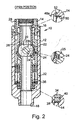
- an apertured ball element Disposed within the valve housing is an apertured ball element, generally indicated by reference numeral 20, which, as will be described, is rotatable through 90° between a closed position, as shown in Fig. 1 , and a fully open position as shown in Fig. 2 .
- the ball element 20 is disposed within a ball cage 22 for totally enclosing the ball, in use, to provide a mechanical barrier against movement of debris from the bore of the tool to the working components as will also be later described.
- the apertured ball element 20 has protruding from its sides two cylindrical bosses or trunnions 24, best seen in Figs. 1 and 5 . These trunnions pass through circular apertures in the cage 22 via main bearings for engaging in windows 25 (best seen in Figs. 1 and 5 ) in valve actuating means in the form of a cylindrical piston 26.
- the apertured ball element is of the type disclosed in applicant's co-pending International Patent Application Publication No. WO 93/03255 .
- the cylindrical piston 26 is shown abutting the lower surface 14a of annular cap 14.
- a hydraulic inlet line 28 Through the left side of the annular cap 14 is shown a hydraulic inlet line 28 through which hydraulic pressure can be applied to piston 26 for rotation of the ball valve as will be later described.
- the base 26a of the piston 26 abuts a top annular plate 30 or gusset ring 30 beneath which is disposed a magazine of forty nested helical coil compression spring stacks 32, of which four are shown in the interests of clarity.
- the spring stacks 32 are spaced around the circumference of the housing, and each stack is located between the top annular plate 30 and a lower plate or end seal 34.
- the spring stacks 32 move between an uncompressed position as shown in Fig. 1 and a compressed position shown in Fig. 2 of the drawings.
- the valve cage 22 is threadedly connected to a mandrel 36 which extends longitudinally within the bore 18 of the housing 16.
- the base 36a of the mandrel 36a has a threaded exterior 38 which is coupled to an external seal ring 40.
- the upper part of the mandrel 36 has a shoulder region 42 against which abuts the top annular plate 30 so that the maximum uncompressed position of the coil springs is as shown in Fig. 1 of the drawings.
- a mandrel Belleville spring 44 Disposed beneath the seal ring 40 is a mandrel Belleville spring 44 which exerts an upward force of approximately 112Kn (25,000 lbs) on the seal ring 40 and mandrel assembly over a short operating range.
- the mandrel spring 44 is shown located beneath the seal ring 40 and a shoulder 46 of the housing 16.
- valve seat 48 Disposed above the ball element 20 is a cylindrical valve seat, generally indicated by reference numeral 48.
- the valve seat is shown in sealing engagement with the upper spherical surface 20a of the ball element 20.
- the upper part 48a of the valve seat 48 is coupled to an upper valve seat spring, generally indicated by reference numeral 50, which exerts a downward spring force of 45Kn (10,000 lbs) to urge the valve seat 48 into contact with the ball element surface 20a.
- the valve seat spring 50 is coupled to the valve seat 48 and is arranged such that upward movement of the valve seat 48 is limited by the valve seat abutting a shoulder portion 52 of the annular valve housing cap 16.
- the trunnions 24 engage with the windows of the piston 26 such that the ball is rotated from the closed position shown in Fig. 1 to the fully open position shown in Fig. 2 such that the bore of the ball element 20b is aligned with the internal bore of the mandrel 36 and the bore of the valve housing 18.
- valve seat spring 50 disposed between the valve seat 48 and the top cap 14 provides a force to the valve seat 48 to "follow" the ball element 20 to the lower position shown in Fig. 2 to maintain a preloaded contact with the surface 20a of the ball element 20 to reduce the possibility of debris from the bore 18, when in the open position shown in Fig. 2 , becoming entrained between the valve seat 48 and the surface 20a of the ball element and thus contaminating the valve components.
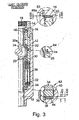
- Fig. 3 of the drawings depicts the valve in what is known as the "just-closed" position.
- the hydraulic actuating force has been removed from the piston 26 and the main helical coil spring stack 32 has returned the piston to its uppermost position thereby rotating the ball element through 90° (as was seen in Fig. 1 ) such that the bore 18 of the valve assembly is blocked to prevent fluid flow therethrough.
- the main coil spring stack 32 has closed the valve and pushed the piston 26 through its 151.2mm (3.0") stroke.
- the spring stack 32 simultaneously shoulders out on the underside of the mandrel shoulder 42.
- the mandrel spring 44 is considerably stronger than the seat spring 50, the mandrel assembly (the mandrel, ball cage and ball element, piston and valve seat) is pushed up until the valve seat 48 shoulders out on the top cap 14 as described above. Although there is no rigid connection between them, the seat and mandrel assembly move as one system due to the preloaded Belleville springs 44,50 at either end of the system.
- Fig. 4 of the drawings depicts the ball valve when the ball element 20 is in the "intensifying" position.
- the ball element 20 has been pushed up onto the valve seat 48 by the mandrel spring 44.
- the mandrel assembly, ball and valve seat have all moved up 0.7mm (0.025") towards the valve cap 14 because of the higher force exerted by the mandrel spring 44 over the seat spring 50. Therefore, the ball element 20 is preloaded onto the valve seat 48 which, in turn, is shouldered out on the top cap 14. Any further forces across the ball element, such as differential pressure, are reacted through this load path thereby providing intensification in proportion to the circular seal contact area.
- Figs. 3 and 4 illustrate the transition between the "just-closed” and “intensifying” positions and it will be appreciated that in Fig. 3 the piston 26 returns the trunnion or pin 24 to the fully closed position best illustrated by the bubble 64. Thereafter, the trunnion or pin 22 is allowed to float axially upwards within its connection with the piston 26. This float allows the valve components to reposition themselves in response to spring force and hydrostatic end loads to the intensifying condition shown in Fig. 4 .
- the piston travel includes both the functional stroke (151.2mm (3.000") ) and the residual force (1.2mm (0.050”) ).
- a number of the helical coil springs 32a on the radially outer portions of the spring stack 36 are arranged to penetrate through the top plate 30 and act directly on the piston 26 as is best seen in Fig. 1 and bubble 66 in Fig. 4 of the drawings.
- These springs 32a provide the main part of the force to deliver the piston 26 to the fully up position but additional force is provided for both the functional and residual portions of piston stroke by the seal arrangement between the piston and the tool bore.
- An inequality of seal diameters between the piston and top cap seal, and between the piston and the mandrel seal means that any pressure in the tool bore has the effect of driving the piston upwards.
- ball valve structure hereinbefore described provides both rotational reliability and seal reliability with the result that the ball valve can be used in aggressive wells environment which have hitherto been impossible with existing valves.
- the ball element may have hardened tungsten carbide edges which are shaped such that actuation of the valve to a closed position provides sufficient force to shear or cut coil tubing and comply with relevant safety requirements.
- the ball valve structure hereinbefore described includes other features which improve the operational reliability.
- the totally enclosed cage 22 engages above the ball 20 with the seat 48 and below the ball with the mandrel 36.
- the cage 22 provides a mechanical barrier against the movement of debris from the bore 18 of the valve structure to the working components of the valve. It is important for the functionality of the valve that any pressure in the bore 18 is allowed to act through the cage and consequently the cage is not pressure retaining in any way.
- valve pumps through are also improved in relation to prior art ball valve structures.
- Previously equalisation of pressure occurred as a result of the ball floating away axially from the seat thereby creating an annular flow path between two components.
- This annular flow path resulted in debris becoming trapped between the ball and the seat when the differential pressure was removed.
- the pump through mechanism now maintains the valve seat 48 in constant contact with the ball surface 20a.
- a portion of the main cylindrical actuation piston 26 is exposed to bore pressure above the ball element 20. When a positive differential pressure is created above the valve, it acts on this portion of the piston 26 which moves downwardly in response. Hence, the ball 20 rotates to a partially open position to allow pump through of fluid.
- the seat spring 50 maintains contact between the ball surface 20a and the valve seat 48 throughout the process.
- Wiper seals have been included in front of all hydraulic seals which are exposed to production water surfaces. These wiper seals displace any debris and protect the hydraulic seals and the respective mating surfaces.
- valve structure hereinbefore described without departing from the scope of the invention as defined by the appended claims.
- valve structure requires 40 helical coil springs it will be appreciated that any suitable number may be used depending on the spring strength.
- the exact spring tensions of the mandrel spring, seat spring and compression strings may be varied, although it is a requirement that the spring force of the mandrel spring be greater than the seat spring sufficient to allow the mandrel assembly to move up to the intensified position, and the spring force in the coil spring stack when in the just-closed position, must be greater than the spring force of the mandrel spring.
- valve housing and internal valve structure may be of any suitable shape to allow the components to be disposed in the valve housing sufficient to achieve the function hereinbefore described, namely that there is an upward movement of the assembly to create an intensified position when the valve is fully closed. It will also be understood that premium corrosion-resistant materials are preferred.
- the principal advantage of the invention over the prior art is that it provides the ball valve structure with both rotational reliability and seal reliability such that it can be used in aggressive well environments.
- the design minimises the possibility of the mechanism binding because the valve seat stays in contact with the ball element throughout its rotation and this also eliminates the possibility of debris ingress between the ball and the seat.
- the provision of wiper seals also protects the hydraulic seals from debris damage and because the ingress of debris is minimised to working components, the component life is increased and this reduces replacement frequency. This effectively increases the working life of the valve.
- the coil spring stack also provides an increase failsafe close spring force which also provides increased passive cutting capacity. Furthermore, because rotational friction forces are minimised valve closure times are significantly reduced.
Landscapes
- Engineering & Computer Science (AREA)
- Geology (AREA)
- Life Sciences & Earth Sciences (AREA)
- General Engineering & Computer Science (AREA)
- Mining & Mineral Resources (AREA)
- Geochemistry & Mineralogy (AREA)
- Fluid Mechanics (AREA)
- General Life Sciences & Earth Sciences (AREA)
- Physics & Mathematics (AREA)
- Environmental & Geological Engineering (AREA)
- Mechanical Engineering (AREA)
- Taps Or Cocks (AREA)
- Temperature-Responsive Valves (AREA)
- Valve Housings (AREA)
- Check Valves (AREA)
- Fuel-Injection Apparatus (AREA)
- External Artificial Organs (AREA)
- Self-Closing Valves And Venting Or Aerating Valves (AREA)
Claims (3)
- Kugelventil (10) für eine Verwendung bei einer Kugelventilkonstruktion, wobei das Kugelventil aufweist: ein mit einer Öffnung versehenes Kugelelement (20) mit einer Ventilelementbohrung (18) und mit Drehzapfen (24), die damit für ein Drehen des Kugelelementes (20) zwischen einer offenen und einer geschlossenen Position als Reaktion auf eine angewandte Kraft verbunden sind; einen Kugelkäfig (22) für das Umgeben des Kugelelementes (20) außer im Bereich der Ventilbohrung, wobei der Käfig (22) durch zwei passende geteilte Schalen gebildet wird, wobei eine jede Schale ein kreisförmiges Fenster (25) darin für das Aufnehmen und Ineingriffkommen mit den Drehzapfen (24) des Kugelelementes (20) mittels Gleitlagern aufweist, wobei die Drehzapfen (24) vom Bohrloch durch den Käfig (22) getrennt sind, wobei der Käfig (22) abdichtend mit einem Ventilsitz (48) auf einer Seite des Kugelelementes (20) in Eingriff kommt und ein unteres Ende des Käfigs (22) mit einem Dorn (36) auf der anderen Seite der Kugel verschraubt ist, wobei die Drehzapfen (24) mit einem zylindrischen Kolben (26) in Eingriff sind, der so ausgebildet ist, dass er geradlinig innerhalb eines Ventilgehäuses als Reaktion auf die Anwendung eines hydraulischen Druckes bewegt wird, so dass sich, wenn der Druck angewandt oder aufgehoben wird, der Kolben (26) in der Richtung der Längsachse der Bohrung bewegt, so dass sich das Kugelelement (20) innerhalb des Käfigs (22) zwischen einer offenen und einer geschlossenen Position bewegt, wobei der Kugelkäfig (22) eine mechanische Sperre für die Bewegung von Bohrklein aus der Bohrung der Kugelventilkonstruktion zu den Drehzapfen (24) der Kugelventilkonstruktion bereitstellt.
- Verfahren zum Ausgleichen des Druckes über ein Kugelventil als Reaktion auf einen Überdruck von oberhalb des Kugelventils, wobei ein Kugelelement (20) in einem Käfig (22) angeordnet ist, wobei der Käfig (22) eine Längsbohrung und das Kugelelement (20) eine Ventilelementbohrung und Drehzapfen (24) aufweist, die mit dem Kugelelement (20) für das Drehen des Kugelelementes (20) innerhalb der Längsbohrung zwischen einer offenen und einer geschlossenen Position als Reaktion auf eine Kraft verbunden sind, die auf eine Ventilbetätigungseinrichtung angewandt wird, so dass, wenn sich das Kugelelement (20) in einer offenen Position befindet, die Ventilelementbohrung mit der Längsbohrung ausgerichtet ist, wobei der Käfig (22) eine mechanische Sperre für die Bewegung von Bohrklein aus der Bohrung des Kugelventils zu den Drehzapfen (24) bereitstellt, wobei das Verfahren den folgenden Schritt aufweist:Aussetzen eines Abschnittes der Ventilbetätigungseinrichtung einem Überdruck in der Längsbohrung über dem Kugelelement (20), der ausreichend ist, damit das Kugelelement (20) aus dem Ventilsitz (48) während der Drehung entnommen wird, aber um mit dem Ventilsitz (48) in Kontakt zu bleiben, um so das Eindringen von Bohrklein zwischen dem Kugelelement (20) und dem Ventilsitz (48) zu verhindern, wobei eine Abwärtsbewegung der Ventilbetätigungseinrichtung als Reaktion auf den Überdruck das Kugelelement (20) in eine teilweise offene Position dreht, um ein Hindurchpumpen von Fluid zu gestatten.
- Verfahren nach Anspruch 2, bei dem das Kugelelement (20) aus dem Ventilsitz (48) mittels eines Kugelhaltemechanismus entnommen wird, wobei der Kugelhaltemechanismus etwa 0,6 mm bewegt wird.
Applications Claiming Priority (3)
| Application Number | Priority Date | Filing Date | Title |
|---|---|---|---|
| GB9819965 | 1998-09-15 | ||
| GBGB9819965.6A GB9819965D0 (en) | 1998-09-15 | 1998-09-15 | Improved ball valve |
| EP99946293A EP1112436B1 (de) | 1998-09-15 | 1999-09-15 | Verbessertes kugelventil |
Related Parent Applications (2)
| Application Number | Title | Priority Date | Filing Date |
|---|---|---|---|
| EP99946293.0 Division | 1999-09-15 | ||
| EP99946293A Division EP1112436B1 (de) | 1998-09-15 | 1999-09-15 | Verbessertes kugelventil |
Publications (2)
| Publication Number | Publication Date |
|---|---|
| EP1439340A1 EP1439340A1 (de) | 2004-07-21 |
| EP1439340B1 true EP1439340B1 (de) | 2013-03-27 |
Family
ID=10838817
Family Applications (2)
| Application Number | Title | Priority Date | Filing Date |
|---|---|---|---|
| EP04008281A Expired - Lifetime EP1439340B1 (de) | 1998-09-15 | 1999-09-15 | Kugelventil |
| EP99946293A Expired - Lifetime EP1112436B1 (de) | 1998-09-15 | 1999-09-15 | Verbessertes kugelventil |
Family Applications After (1)
| Application Number | Title | Priority Date | Filing Date |
|---|---|---|---|
| EP99946293A Expired - Lifetime EP1112436B1 (de) | 1998-09-15 | 1999-09-15 | Verbessertes kugelventil |
Country Status (10)
| Country | Link |
|---|---|
| US (1) | US6708946B1 (de) |
| EP (2) | EP1439340B1 (de) |
| AT (1) | ATE283964T1 (de) |
| AU (1) | AU750243B2 (de) |
| BR (1) | BR9913769B1 (de) |
| CA (1) | CA2343910C (de) |
| DE (1) | DE69922385D1 (de) |
| GB (1) | GB9819965D0 (de) |
| NO (1) | NO322591B1 (de) |
| WO (1) | WO2000015943A1 (de) |
Families Citing this family (54)
| Publication number | Priority date | Publication date | Assignee | Title |
|---|---|---|---|---|
| US6698712B2 (en) | 2002-05-02 | 2004-03-02 | Dril-Quip, Inc. | Ball valve assembly |
| US7195225B1 (en) | 2003-10-30 | 2007-03-27 | Dril-Quip, Inc. | Rotary valve assembly |
| GB0401440D0 (en) * | 2004-01-23 | 2004-02-25 | Enovate Systems Ltd | Completion suspension valve system |
| GB0423015D0 (en) * | 2004-10-16 | 2004-11-17 | Enovate Systems Ltd | Improved ball valve |
| US7469708B2 (en) * | 2004-12-21 | 2008-12-30 | Fisher Controls International Llc | Universal fluid valve body |
| US20080099712A1 (en) * | 2006-10-25 | 2008-05-01 | Honeywell International Inc. | Cartridge ball valve |
| US8225871B2 (en) * | 2006-11-09 | 2012-07-24 | Baker Hughes Incorporated | Bidirectional sealing mechanically shifted ball valve for downhole use |
| US7810571B2 (en) * | 2006-11-09 | 2010-10-12 | Baker Hughes Incorporated | Downhole lubricator valve |
| US8113286B2 (en) * | 2006-11-09 | 2012-02-14 | Baker Hughes Incorporated | Downhole barrier valve |
| US7854257B2 (en) * | 2007-02-15 | 2010-12-21 | Baker Hughes Incorporated | Mechanically coupled screen and method |
| GB2451288B (en) * | 2007-07-27 | 2011-12-21 | Red Spider Technology Ltd | Downhole valve assembley, actuation device for a downhole vavle assembley and method for controlling fluid flow downhole |
| US7628210B2 (en) | 2007-08-13 | 2009-12-08 | Baker Hughes Incorporated | Ball seat having ball support member |
| US7673677B2 (en) | 2007-08-13 | 2010-03-09 | Baker Hughes Incorporated | Reusable ball seat having ball support member |
| US7503392B2 (en) | 2007-08-13 | 2009-03-17 | Baker Hughes Incorporated | Deformable ball seat |
| US7637323B2 (en) | 2007-08-13 | 2009-12-29 | Baker Hughes Incorporated | Ball seat having fluid activated ball support |
| US7971855B2 (en) * | 2008-12-09 | 2011-07-05 | Big Horn Valve, Inc. | Stemless ball valve |
| RU2391592C1 (ru) * | 2008-12-30 | 2010-06-10 | Владимир Александрович Чигряй | Обратный клапан |
| US7905292B2 (en) * | 2009-02-06 | 2011-03-15 | Baker Hughes Incorporated | Pressure equalization device for downhole tools |
| US8398053B2 (en) * | 2009-04-29 | 2013-03-19 | Bp Corporation North America Inc. | Double piston trunnion mounted ball valves and methods of use |
| US8261761B2 (en) | 2009-05-07 | 2012-09-11 | Baker Hughes Incorporated | Selectively movable seat arrangement and method |
| US8479823B2 (en) | 2009-09-22 | 2013-07-09 | Baker Hughes Incorporated | Plug counter and method |
| US8534361B2 (en) * | 2009-10-07 | 2013-09-17 | Baker Hughes Incorporated | Multi-stage pressure equalization valve assembly for subterranean valves |
| US8336628B2 (en) * | 2009-10-20 | 2012-12-25 | Baker Hughes Incorporated | Pressure equalizing a ball valve through an upper seal bypass |
| US8789600B2 (en) | 2010-08-24 | 2014-07-29 | Baker Hughes Incorporated | Fracing system and method |
| US8490946B2 (en) * | 2011-01-21 | 2013-07-23 | Big Horn Valve, Inc. | Planetary gear valve |
| CN102071912A (zh) * | 2011-01-26 | 2011-05-25 | 哈尔滨福铭制造有限责任公司 | 井下液控开关器 |
| US8662183B1 (en) * | 2011-02-12 | 2014-03-04 | Louis P. Vickio, Jr. | Blow out preventer |
| US8668018B2 (en) | 2011-03-10 | 2014-03-11 | Baker Hughes Incorporated | Selective dart system for actuating downhole tools and methods of using same |
| US8668006B2 (en) | 2011-04-13 | 2014-03-11 | Baker Hughes Incorporated | Ball seat having ball support member |
| US8727315B2 (en) | 2011-05-27 | 2014-05-20 | Halliburton Energy Services, Inc. | Ball valve |
| US8479808B2 (en) | 2011-06-01 | 2013-07-09 | Baker Hughes Incorporated | Downhole tools having radially expandable seat member |
| US9145758B2 (en) | 2011-06-09 | 2015-09-29 | Baker Hughes Incorporated | Sleeved ball seat |
| GB2493180A (en) * | 2011-07-27 | 2013-01-30 | Expro North Sea Ltd | Valve housing arrangement |
| EP2568109B1 (de) * | 2011-09-06 | 2015-02-25 | Vetco Gray Inc. | Kugelventilanordnung |
| US9371918B2 (en) * | 2011-09-30 | 2016-06-21 | Weatherford Technology Holdings, Llc | Ball valve float equipment |
| US9004091B2 (en) | 2011-12-08 | 2015-04-14 | Baker Hughes Incorporated | Shape-memory apparatuses for restricting fluid flow through a conduit and methods of using same |
| WO2013112195A1 (en) * | 2012-01-28 | 2013-08-01 | Big Horn Valve, Inc. | Planetary gear ball valve |
| US9016388B2 (en) | 2012-02-03 | 2015-04-28 | Baker Hughes Incorporated | Wiper plug elements and methods of stimulating a wellbore environment |
| USD671204S1 (en) * | 2012-02-14 | 2012-11-20 | Steffes Corporation | Flare stack burner assembly |
| US8925894B2 (en) * | 2012-02-17 | 2015-01-06 | Vetco Gray Inc. | Ball valve enclosure and drive mechanism |
| US20140209314A1 (en) * | 2013-01-28 | 2014-07-31 | Schlumberger Technology Corporation | Shear and seal system for subsea applications |
| DE102013002223B4 (de) | 2013-02-11 | 2018-03-22 | Armaturenfabrik Franz Schneider GmbH + Co. KG | Kugelhahnvorrichtung |
| WO2014193405A1 (en) * | 2013-05-31 | 2014-12-04 | Halliburton Energy Services, Inc. | Annulus activated ball valve assembly |
| BR112016028013B1 (pt) * | 2014-07-02 | 2022-05-10 | Halliburton Energy Services, Inc | Conjunto de válvula, sistema de atuação de válvula sem contato, e, método para atuar uma válvula |
| AU2014414096B2 (en) * | 2014-12-17 | 2017-12-14 | Halliburton Energy Services, Inc. | Valve for use with downhole tools |
| US10246971B2 (en) | 2015-09-24 | 2019-04-02 | Baker Hughes, A Ge Company, Llc | Flow activated valve |
| GB2543077B (en) * | 2015-10-08 | 2021-12-22 | Welleng Science & Tech Ltd | Downhole valve |
| WO2018035124A1 (en) | 2016-08-17 | 2018-02-22 | Quipip, Llc | Sensing device, and systems and methods for obtaining data relating to concrete mixtures and concrete structures |
| CN107829709B (zh) * | 2017-11-11 | 2020-07-14 | 中石化石油工程技术服务有限公司 | 全通径压控测试阀 |
| RU2704161C1 (ru) * | 2018-11-29 | 2019-10-24 | Общество с ограниченной ответственностью "Газпром 335" | Верхний изолирующий клапан |
| DE102018132448A1 (de) * | 2018-12-17 | 2020-06-18 | ECO Holding 1 GmbH | Expansionsventil für Kältemittel und Klimaanlage, Wärmemanagementsystem und Batteriekühlsystem mit einem Expansionsventil |
| US11655902B2 (en) * | 2019-06-24 | 2023-05-23 | Onesubsea Ip Uk Limited | Failsafe close valve assembly |
| US11952864B2 (en) * | 2020-07-09 | 2024-04-09 | Schlumberger Technology Corporation | Disengaging piston for linear actuation |
| US11988209B2 (en) | 2021-12-03 | 2024-05-21 | Hamilton Sundstrand Corporation | Spring retainer for gear pump bearing plate |
Family Cites Families (18)
| Publication number | Priority date | Publication date | Assignee | Title |
|---|---|---|---|---|
| USRE25471E (en) * | 1963-11-05 | V fredd | ||
| US3236255A (en) * | 1963-04-24 | 1966-02-22 | Phillip S Sizer | Pressure operated safety valve |
| US3276740A (en) * | 1963-10-04 | 1966-10-04 | Keystone Valve Corp | Valve |
| US3457991A (en) * | 1968-02-16 | 1969-07-29 | Phillip S Sizer | Well tools |
| US3729170A (en) * | 1969-02-20 | 1973-04-24 | Hydril Co | Rotary plug valve assembly |
| US3743015A (en) * | 1971-09-07 | 1973-07-03 | Hydril Co | Mud saver valve |
| USRE28131E (en) * | 1973-10-26 | 1974-08-20 | Ball valve with resilient seal | |
| US3901321A (en) | 1973-12-26 | 1975-08-26 | Hydril Co | Safety valve method and apparatus |
| US4009753A (en) * | 1976-03-22 | 1977-03-01 | Schlumberger Technology Corporation | Subsea master valve apparatus |
| US4368871A (en) * | 1977-10-03 | 1983-01-18 | Schlumberger Technology Corporation | Lubricator valve apparatus |
| US4144937A (en) * | 1977-12-19 | 1979-03-20 | Halliburton Company | Valve closing method and apparatus for use with an oil well valve |
| US4352366A (en) * | 1980-02-05 | 1982-10-05 | Otis Engineering Corporation | Velocity operated standing valve |
| US4469180A (en) * | 1981-10-21 | 1984-09-04 | Hydril Company | Well fluid pressure balanced operator for subsurface safety valve |
| US4422618A (en) * | 1981-12-01 | 1983-12-27 | Armco Inc. | Remotely operated valve |
| US4448216A (en) * | 1982-03-15 | 1984-05-15 | Otis Engineering Corporation | Subsurface safety valve |
| US4603740A (en) * | 1984-08-29 | 1986-08-05 | Hydril Company | Subsurface safety valve |
| GB9117119D0 (en) | 1991-08-08 | 1991-09-25 | Exploration And Production Nor | Tubing test valve |
| US5551665A (en) * | 1994-04-29 | 1996-09-03 | Halliburton Company | Ball valve with coiled tubing cutting ability |
-
1998
- 1998-09-15 GB GBGB9819965.6A patent/GB9819965D0/en not_active Ceased
-
1999
- 1999-09-15 AU AU58713/99A patent/AU750243B2/en not_active Expired
- 1999-09-15 DE DE69922385T patent/DE69922385D1/de not_active Expired - Lifetime
- 1999-09-15 US US09/787,188 patent/US6708946B1/en not_active Expired - Lifetime
- 1999-09-15 BR BRPI9913769-0A patent/BR9913769B1/pt not_active IP Right Cessation
- 1999-09-15 EP EP04008281A patent/EP1439340B1/de not_active Expired - Lifetime
- 1999-09-15 WO PCT/GB1999/002886 patent/WO2000015943A1/en not_active Ceased
- 1999-09-15 CA CA002343910A patent/CA2343910C/en not_active Expired - Lifetime
- 1999-09-15 AT AT99946293T patent/ATE283964T1/de not_active IP Right Cessation
- 1999-09-15 EP EP99946293A patent/EP1112436B1/de not_active Expired - Lifetime
-
2001
- 2001-03-09 NO NO20011200A patent/NO322591B1/no not_active IP Right Cessation
Also Published As
| Publication number | Publication date |
|---|---|
| DE69922385D1 (de) | 2005-01-05 |
| EP1439340A1 (de) | 2004-07-21 |
| BR9913769A (pt) | 2001-06-05 |
| CA2343910C (en) | 2007-12-18 |
| EP1112436A1 (de) | 2001-07-04 |
| NO20011200L (no) | 2001-05-10 |
| AU750243B2 (en) | 2002-07-11 |
| NO20011200D0 (no) | 2001-03-09 |
| WO2000015943A1 (en) | 2000-03-23 |
| AU5871399A (en) | 2000-04-03 |
| BR9913769B1 (pt) | 2008-11-18 |
| EP1112436B1 (de) | 2004-12-01 |
| NO322591B1 (no) | 2006-10-30 |
| CA2343910A1 (en) | 2000-03-23 |
| GB9819965D0 (en) | 1998-11-04 |
| US6708946B1 (en) | 2004-03-23 |
| ATE283964T1 (de) | 2004-12-15 |
Similar Documents
| Publication | Publication Date | Title |
|---|---|---|
| EP1439340B1 (de) | Kugelventil | |
| EP0596900B1 (de) | Ventilbetaetiger | |
| US4809733A (en) | Fail-safe gate valve with separated actuators | |
| US4429620A (en) | Hydraulically operated actuator | |
| US4856557A (en) | Sliding metal seal valve mechanism | |
| US20030116200A1 (en) | Valve actuator and method | |
| EP0679796B1 (de) | Kugelventil | |
| EP3555418B1 (de) | Ausgeglichene ventilanordnung | |
| AU2019371796B2 (en) | Valve with pressure differrential seating | |
| EP3857020B1 (de) | Kolbenlastringdichtungskonfigurationen | |
| US4641682A (en) | Valve with rotary valve head | |
| US7963339B2 (en) | Bearing mounted ball valve and method of use | |
| EP1825176B1 (de) | Axial erregbares kugelventil | |
| US20110198527A1 (en) | Axially energisable ball valve | |
| US5975212A (en) | Surface controlled subsurface safety valve downstop seal | |
| EP2609283B1 (de) | Durchpumpzirkulations- und/oder sicherheitszirkulationsventil | |
| WO2013191783A2 (en) | Multi-barrier seal system | |
| GB2043780A (en) | Hydraulically Operated Actuator |
Legal Events
| Date | Code | Title | Description |
|---|---|---|---|
| PUAI | Public reference made under article 153(3) epc to a published international application that has entered the european phase |
Free format text: ORIGINAL CODE: 0009012 |
|
| 17P | Request for examination filed |
Effective date: 20040426 |
|
| AC | Divisional application: reference to earlier application |
Ref document number: 1112436 Country of ref document: EP Kind code of ref document: P |
|
| AK | Designated contracting states |
Kind code of ref document: A1 Designated state(s): AT BE CH CY DE DK ES FI FR GB GR IE IT LI LU MC NL PT SE |
|
| 17Q | First examination report despatched |
Effective date: 20050113 |
|
| AKX | Designation fees paid |
Designated state(s): AT BE CH CY DE DK ES FI FR GB GR IE IT LI LU MC NL PT SE |
|
| GRAP | Despatch of communication of intention to grant a patent |
Free format text: ORIGINAL CODE: EPIDOSNIGR1 |
|
| GRAS | Grant fee paid |
Free format text: ORIGINAL CODE: EPIDOSNIGR3 |
|
| GRAA | (expected) grant |
Free format text: ORIGINAL CODE: 0009210 |
|
| AC | Divisional application: reference to earlier application |
Ref document number: 1112436 Country of ref document: EP Kind code of ref document: P |
|
| AK | Designated contracting states |
Kind code of ref document: B1 Designated state(s): AT BE CH CY DE DK ES FI FR GB GR IE IT LI LU MC NL PT SE |
|
| REG | Reference to a national code |
Ref country code: GB Ref legal event code: FG4D |
|
| REG | Reference to a national code |
Ref country code: CH Ref legal event code: EP |
|
| REG | Reference to a national code |
Ref country code: AT Ref legal event code: REF Ref document number: 603616 Country of ref document: AT Kind code of ref document: T Effective date: 20130415 |
|
| REG | Reference to a national code |
Ref country code: IE Ref legal event code: FG4D |
|
| REG | Reference to a national code |
Ref country code: DE Ref legal event code: R096 Ref document number: 69944685 Country of ref document: DE Effective date: 20130523 |
|
| PG25 | Lapsed in a contracting state [announced via postgrant information from national office to epo] |
Ref country code: SE Free format text: LAPSE BECAUSE OF FAILURE TO SUBMIT A TRANSLATION OF THE DESCRIPTION OR TO PAY THE FEE WITHIN THE PRESCRIBED TIME-LIMIT Effective date: 20130327 |
|
| REG | Reference to a national code |
Ref country code: AT Ref legal event code: MK05 Ref document number: 603616 Country of ref document: AT Kind code of ref document: T Effective date: 20130327 |
|
| PG25 | Lapsed in a contracting state [announced via postgrant information from national office to epo] |
Ref country code: GR Free format text: LAPSE BECAUSE OF FAILURE TO SUBMIT A TRANSLATION OF THE DESCRIPTION OR TO PAY THE FEE WITHIN THE PRESCRIBED TIME-LIMIT Effective date: 20130628 Ref country code: FI Free format text: LAPSE BECAUSE OF FAILURE TO SUBMIT A TRANSLATION OF THE DESCRIPTION OR TO PAY THE FEE WITHIN THE PRESCRIBED TIME-LIMIT Effective date: 20130327 |
|
| REG | Reference to a national code |
Ref country code: NL Ref legal event code: VDEP Effective date: 20130327 |
|
| PG25 | Lapsed in a contracting state [announced via postgrant information from national office to epo] |
Ref country code: BE Free format text: LAPSE BECAUSE OF FAILURE TO SUBMIT A TRANSLATION OF THE DESCRIPTION OR TO PAY THE FEE WITHIN THE PRESCRIBED TIME-LIMIT Effective date: 20130327 |
|
| PG25 | Lapsed in a contracting state [announced via postgrant information from national office to epo] |
Ref country code: AT Free format text: LAPSE BECAUSE OF FAILURE TO SUBMIT A TRANSLATION OF THE DESCRIPTION OR TO PAY THE FEE WITHIN THE PRESCRIBED TIME-LIMIT Effective date: 20130327 Ref country code: ES Free format text: LAPSE BECAUSE OF FAILURE TO SUBMIT A TRANSLATION OF THE DESCRIPTION OR TO PAY THE FEE WITHIN THE PRESCRIBED TIME-LIMIT Effective date: 20130708 Ref country code: PT Free format text: LAPSE BECAUSE OF FAILURE TO SUBMIT A TRANSLATION OF THE DESCRIPTION OR TO PAY THE FEE WITHIN THE PRESCRIBED TIME-LIMIT Effective date: 20130729 Ref country code: NL Free format text: LAPSE BECAUSE OF FAILURE TO SUBMIT A TRANSLATION OF THE DESCRIPTION OR TO PAY THE FEE WITHIN THE PRESCRIBED TIME-LIMIT Effective date: 20130327 |
|
| PG25 | Lapsed in a contracting state [announced via postgrant information from national office to epo] |
Ref country code: CY Free format text: LAPSE BECAUSE OF FAILURE TO SUBMIT A TRANSLATION OF THE DESCRIPTION OR TO PAY THE FEE WITHIN THE PRESCRIBED TIME-LIMIT Effective date: 20130327 |
|
| PG25 | Lapsed in a contracting state [announced via postgrant information from national office to epo] |
Ref country code: DK Free format text: LAPSE BECAUSE OF FAILURE TO SUBMIT A TRANSLATION OF THE DESCRIPTION OR TO PAY THE FEE WITHIN THE PRESCRIBED TIME-LIMIT Effective date: 20130327 |
|
| PLBE | No opposition filed within time limit |
Free format text: ORIGINAL CODE: 0009261 |
|
| STAA | Information on the status of an ep patent application or granted ep patent |
Free format text: STATUS: NO OPPOSITION FILED WITHIN TIME LIMIT |
|
| PG25 | Lapsed in a contracting state [announced via postgrant information from national office to epo] |
Ref country code: IT Free format text: LAPSE BECAUSE OF FAILURE TO SUBMIT A TRANSLATION OF THE DESCRIPTION OR TO PAY THE FEE WITHIN THE PRESCRIBED TIME-LIMIT Effective date: 20130327 |
|
| 26N | No opposition filed |
Effective date: 20140103 |
|
| REG | Reference to a national code |
Ref country code: DE Ref legal event code: R097 Ref document number: 69944685 Country of ref document: DE Effective date: 20140103 |
|
| PG25 | Lapsed in a contracting state [announced via postgrant information from national office to epo] |
Ref country code: MC Free format text: LAPSE BECAUSE OF FAILURE TO SUBMIT A TRANSLATION OF THE DESCRIPTION OR TO PAY THE FEE WITHIN THE PRESCRIBED TIME-LIMIT Effective date: 20130327 |
|
| REG | Reference to a national code |
Ref country code: CH Ref legal event code: PL |
|
| REG | Reference to a national code |
Ref country code: DE Ref legal event code: R119 Ref document number: 69944685 Country of ref document: DE Effective date: 20140401 |
|
| REG | Reference to a national code |
Ref country code: FR Ref legal event code: ST Effective date: 20140530 |
|
| REG | Reference to a national code |
Ref country code: IE Ref legal event code: MM4A |
|
| PG25 | Lapsed in a contracting state [announced via postgrant information from national office to epo] |
Ref country code: LI Free format text: LAPSE BECAUSE OF NON-PAYMENT OF DUE FEES Effective date: 20130930 Ref country code: IE Free format text: LAPSE BECAUSE OF NON-PAYMENT OF DUE FEES Effective date: 20130915 Ref country code: CH Free format text: LAPSE BECAUSE OF NON-PAYMENT OF DUE FEES Effective date: 20130930 |
|
| PG25 | Lapsed in a contracting state [announced via postgrant information from national office to epo] |
Ref country code: DE Free format text: LAPSE BECAUSE OF NON-PAYMENT OF DUE FEES Effective date: 20140401 Ref country code: FR Free format text: LAPSE BECAUSE OF NON-PAYMENT OF DUE FEES Effective date: 20130930 |
|
| PG25 | Lapsed in a contracting state [announced via postgrant information from national office to epo] |
Ref country code: LU Free format text: LAPSE BECAUSE OF NON-PAYMENT OF DUE FEES Effective date: 20130915 |
|
| PGFP | Annual fee paid to national office [announced via postgrant information from national office to epo] |
Ref country code: GB Payment date: 20180927 Year of fee payment: 20 |
|
| REG | Reference to a national code |
Ref country code: GB Ref legal event code: PE20 Expiry date: 20190914 |
|
| PG25 | Lapsed in a contracting state [announced via postgrant information from national office to epo] |
Ref country code: GB Free format text: LAPSE BECAUSE OF EXPIRATION OF PROTECTION Effective date: 20190914 |