EP1439316A2 - Dispositif de retenue pour organe de liaison, et système découpleur equipé d'un tel dispositif - Google Patents
Dispositif de retenue pour organe de liaison, et système découpleur equipé d'un tel dispositif Download PDFInfo
- Publication number
- EP1439316A2 EP1439316A2 EP04100113A EP04100113A EP1439316A2 EP 1439316 A2 EP1439316 A2 EP 1439316A2 EP 04100113 A EP04100113 A EP 04100113A EP 04100113 A EP04100113 A EP 04100113A EP 1439316 A2 EP1439316 A2 EP 1439316A2
- Authority
- EP
- European Patent Office
- Prior art keywords
- connecting member
- movable part
- fixed part
- fixed
- flange
- Prior art date
- Legal status (The legal status is an assumption and is not a legal conclusion. Google has not performed a legal analysis and makes no representation as to the accuracy of the status listed.)
- Granted
Links
- 230000000717 retained effect Effects 0.000 claims abstract description 5
- 230000003100 immobilizing effect Effects 0.000 claims description 7
- 210000000056 organ Anatomy 0.000 abstract description 9
- 230000004308 accommodation Effects 0.000 abstract 2
- 230000002093 peripheral effect Effects 0.000 description 16
- 210000003462 vein Anatomy 0.000 description 4
- 125000004122 cyclic group Chemical group 0.000 description 3
- 230000006866 deterioration Effects 0.000 description 3
- 238000006073 displacement reaction Methods 0.000 description 2
- 230000000694 effects Effects 0.000 description 2
- 241001080024 Telles Species 0.000 description 1
- 230000006378 damage Effects 0.000 description 1
- 238000010790 dilution Methods 0.000 description 1
- 239000012895 dilution Substances 0.000 description 1
- 230000007257 malfunction Effects 0.000 description 1
- 230000007306 turnover Effects 0.000 description 1
Images



Classifications
-
- F—MECHANICAL ENGINEERING; LIGHTING; HEATING; WEAPONS; BLASTING
- F16—ENGINEERING ELEMENTS AND UNITS; GENERAL MEASURES FOR PRODUCING AND MAINTAINING EFFECTIVE FUNCTIONING OF MACHINES OR INSTALLATIONS; THERMAL INSULATION IN GENERAL
- F16B—DEVICES FOR FASTENING OR SECURING CONSTRUCTIONAL ELEMENTS OR MACHINE PARTS TOGETHER, e.g. NAILS, BOLTS, CIRCLIPS, CLAMPS, CLIPS OR WEDGES; JOINTS OR JOINTING
- F16B41/00—Measures against loss of bolts, nuts, or pins; Measures against unauthorised operation of bolts, nuts or pins
- F16B41/002—Measures against loss of bolts, nuts or pins
-
- F—MECHANICAL ENGINEERING; LIGHTING; HEATING; WEAPONS; BLASTING
- F01—MACHINES OR ENGINES IN GENERAL; ENGINE PLANTS IN GENERAL; STEAM ENGINES
- F01D—NON-POSITIVE DISPLACEMENT MACHINES OR ENGINES, e.g. STEAM TURBINES
- F01D21/00—Shutting-down of machines or engines, e.g. in emergency; Regulating, controlling, or safety means not otherwise provided for
- F01D21/04—Shutting-down of machines or engines, e.g. in emergency; Regulating, controlling, or safety means not otherwise provided for responsive to undesired position of rotor relative to stator or to breaking-off of a part of the rotor, e.g. indicating such position
- F01D21/045—Shutting-down of machines or engines, e.g. in emergency; Regulating, controlling, or safety means not otherwise provided for responsive to undesired position of rotor relative to stator or to breaking-off of a part of the rotor, e.g. indicating such position special arrangements in stators or in rotors dealing with breaking-off of part of rotor
-
- F—MECHANICAL ENGINEERING; LIGHTING; HEATING; WEAPONS; BLASTING
- F01—MACHINES OR ENGINES IN GENERAL; ENGINE PLANTS IN GENERAL; STEAM ENGINES
- F01D—NON-POSITIVE DISPLACEMENT MACHINES OR ENGINES, e.g. STEAM TURBINES
- F01D25/00—Component parts, details, or accessories, not provided for in, or of interest apart from, other groups
- F01D25/16—Arrangement of bearings; Supporting or mounting bearings in casings
-
- F—MECHANICAL ENGINEERING; LIGHTING; HEATING; WEAPONS; BLASTING
- F16—ENGINEERING ELEMENTS AND UNITS; GENERAL MEASURES FOR PRODUCING AND MAINTAINING EFFECTIVE FUNCTIONING OF MACHINES OR INSTALLATIONS; THERMAL INSULATION IN GENERAL
- F16B—DEVICES FOR FASTENING OR SECURING CONSTRUCTIONAL ELEMENTS OR MACHINE PARTS TOGETHER, e.g. NAILS, BOLTS, CIRCLIPS, CLAMPS, CLIPS OR WEDGES; JOINTS OR JOINTING
- F16B2200/00—Constructional details of connections not covered for in other groups of this subclass
- F16B2200/50—Flanged connections
- F16B2200/506—Flanged connections bolted or riveted
-
- F—MECHANICAL ENGINEERING; LIGHTING; HEATING; WEAPONS; BLASTING
- F16—ENGINEERING ELEMENTS AND UNITS; GENERAL MEASURES FOR PRODUCING AND MAINTAINING EFFECTIVE FUNCTIONING OF MACHINES OR INSTALLATIONS; THERMAL INSULATION IN GENERAL
- F16B—DEVICES FOR FASTENING OR SECURING CONSTRUCTIONAL ELEMENTS OR MACHINE PARTS TOGETHER, e.g. NAILS, BOLTS, CIRCLIPS, CLAMPS, CLIPS OR WEDGES; JOINTS OR JOINTING
- F16B2200/00—Constructional details of connections not covered for in other groups of this subclass
- F16B2200/63—Frangible connections
-
- F—MECHANICAL ENGINEERING; LIGHTING; HEATING; WEAPONS; BLASTING
- F16—ENGINEERING ELEMENTS AND UNITS; GENERAL MEASURES FOR PRODUCING AND MAINTAINING EFFECTIVE FUNCTIONING OF MACHINES OR INSTALLATIONS; THERMAL INSULATION IN GENERAL
- F16B—DEVICES FOR FASTENING OR SECURING CONSTRUCTIONAL ELEMENTS OR MACHINE PARTS TOGETHER, e.g. NAILS, BOLTS, CIRCLIPS, CLAMPS, CLIPS OR WEDGES; JOINTS OR JOINTING
- F16B31/00—Screwed connections specially modified in view of tensile load; Break-bolts
- F16B31/02—Screwed connections specially modified in view of tensile load; Break-bolts for indicating the attainment of a particular tensile load or limiting tensile load
- F16B31/021—Screwed connections specially modified in view of tensile load; Break-bolts for indicating the attainment of a particular tensile load or limiting tensile load by means of a frangible part
Definitions
- the present invention relates to a mechanical assembly system for parts.
- the liaison body may for example be a bolt, ensuring the assembly of the parts.
- the inventive retainer is particularly suitable when organ rupture of bonding is brought about voluntarily, as by example in the case of a decoupler system.
- a decoupler system is a parts assembly system, capable of ensuring the decoupling of said parts when the load applied reaches or exceeds a predetermined charge value.
- a decoupler system is made up of connection, for example bolts. Decoupling is caused by the rupture of the connecting members.
- the present invention also relates to a decoupler system fitted with a retainer according to the invention.
- a tensile screw decoupler system is implemented in document FR 2 752 024.
- This document describes a bearing support which maintains a turnover.
- the bearing support is fixed to a housing by a flange associated with a set of screws assembly all parallel to the shaft axis engine.
- the decoupler system includes screws assembly arranged between the bearing support and the casing.
- the decoupler system of the prior art which has just been described has a drawback major, when the cap screws break. In effect, the screw heads and the free ends of the screw heads are no longer held together, and are likely to be projected in the environment of the decoupler system. This results in a significant risk deterioration or even destruction of this environment.
- the object of the present invention is to remedy the above-mentioned drawback.
- the invention provides a device for restraint, suitable for equipping a decoupling system, which allows to retain portions of bolts, or other liaison bodies, which are likely to be projected in the environment of the decoupler system when decoupling occurs.
- the decoupler system is equipped with at least one device retainer according to the invention.
- the restraint device according to the invention will be presented in a situation where it is associated with a decoupling system, said decoupling system equipping a fan shaft in a turbojet engine.
- the invention is not limited to such a situation, and can be used in other configurations parts assembly.
- Figure 1 is illustrated part of turbojet engine constituting a potential environment for the device of the invention.
- a fan 4 of an axis 100 turbojet engine driven and supported by a rotating shaft 6 is located in front of a line of low pressure trees 2.
- the fan 6 is provided with blades 8 which extend in front of the entrance to an internal vein 10 or vein main gas flow, and in front of the entrance an external vein 12, surrounding the internal vein 10 and that borrows the gas dilution air.
- the rotating shaft 6 carries the blower 4 to its front end 5 and extends backwards from the blower 6.
- the shaft 6 is connected to its rear end 7 to a peripheral part 14 of a structure in crown 15.
- Said peripheral part 14 is movable in axial translation with respect to the structure in crown 15, by means of rollers 144 and means of reminder 146.
- a casing 16 is fixed to a fixed structure 18 and a support 20.
- two decoupler systems 42, 44 are interposed, respectively between the rear end of the shaft 7 and the peripheral part 14 of the crown structure 15, and between the casing 16 and the support 20.
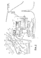
- Figures 2 and 3 are respectively enlarged views of the area where these two intervene decoupler systems 42 and 44.
- FIGS 2 and 3 are shown the shaft 6, and its rear end 7, the structure in crown 15, the peripheral part 14 of the structure in ring 15 and its axial translation means 144, 146, the housing 16, the fixed structure 18, and the support 20.
- the rear end 7 of the shaft 6 has an assembly flange 72 and the peripheral part of the peripheral part 14 of the crown structure 15 has an assembly flange 142.
- the two flanges are connected to each other by a set of connecting members 52 distributed over the periphery of the two assembly flanges 72, 142.
- said connecting members 52 are bolt type, each consisting of a screw 54 and a clamping nut 56.
- the assembly screws 54 are of the type fuse, i.e. having a brittle area which constitutes a beginning of rupture.
- the system decoupler 42 here consists of the connecting members 52 and two assembly flanges 72, 142 which each have bores suitable for reception liaison bodies 52.
- the casing 16 has an assembly zone 162 thinned and angled, for its connection with the end 202 of the support 20, said end 202 being shaped in assembly flange.
- the assembly flange 202 and the assembly area 162 are connected to each other by a set of connecting members 62 distributed over the periphery of the assembly flange 202 and on a circumference of the assembly zone 162.
- said connecting members 62 are also of the bolt type, each consisting of a screw assembly 64 and a clamping nut 66.
- the assembly screws 56 are of the type fuse, i.e. having a brittle area which constitutes a beginning of rupture.
- the system decoupler 44 here consists of the connecting members 62, the assembly flange 202 and the zone 162 which each have bores suitable for receiving the connecting members 62.
- the shaft 6 moves towards forward.
- the amplitude of its displacement is limited by stops 80 formed by reliefs 82 of the shaft 6 which strike a peripheral wall 84 of the housing 16.
- the displacement of the shaft 6 forwards causes the ends of the screw rods to collide 54 carrying the nuts 56 with notches 86 of the casing 16, which causes the rupture of the connecting members 52 of the decoupling system 42.
- the second decoupling has occurred (arrow 222).
- FIG. 3 shows how portions 58 and 68 of the connecting members 52, 62 are suddenly find themselves released by the breach of said connecting members 52, 62, and are projected in the environment of the two decoupler systems 42, 44.
- These portions 58, 68 are here constituted by a portion of the rods of the screws 54, 64 carrying respectively the nuts 56, 66. It appears on observation of the Figure 3 that the projection of these portions 58, 68 in the environment creates a risk of deterioration of parts they reach and / or a malfunction rooms where they can go stuck.
- Figure 3 also shows that the other portion 69 resulting from the rupture of the connecting member 62 stays in place due to the special geometry assembly area 162, which is advantageously thinned and angled.
- Figure 3 finally illustrates how way a device 110 according to the invention is able to retain the second portion 59 of the link 52 of the decoupler system 42 acting between the shaft 6 and the peripheral part 14 of the structure in crown 15.
- the presence of this device 110 is particularly advantageous when the geometry of decoupled parts, here the periphery of the structure in crown 14 and the rear end 7 of the shaft 6, is not designed to hold portions of organs from bond that are released by breaking said liaison bodies.
- Figures 4 and 5 show a view enlarges the connection between the peripheral part 14 of the crown structure 15 and the rear end 7 of tree 6, respectively before and after the second decoupling.
- connection 52 of axes 50 each consisting of a screw 54 and a clamping nut 56.
- the screw 54 has a screw head 53 and a screw rod 55.
- the assembly screw 54 is of the fuse type, it has a zone of fragility 57 to initiate the break.
- the device 110 illustrated in FIG. 4 is intended to retain the portion of connecting member 52 constituted by the head 53 of the screw 54 and by a part adjacent to the rod 55 of said screw 54. It is therefore arranged in the immediate vicinity of the assembly flange which is on the side of the head 53 of the screw 54, here the assembly flange 142 of the peripheral part 14 of the crown structure 15.
- the device 110 includes a fixed part 112, integral with a projected transverse wall 148 of the peripheral part 14 of the crown structure 15.
- the fixed part 112 is an inner sleeve arranged in the extension of the connecting member 52, along the axis 50 thereof.
- the device 110 comprises a part mobile 114, able to slide relative to the part fixed 112.
- the movable part 114 is a socket exterior arranged in the extension of the link 52, along the axis 50 thereof.
- the socket outer 114 surrounds the inner sleeve 112, the two sockets being concentric.
- the outer sleeve 114 presents towards that of its ends closest to the flange 142 an inside edge 122.
- This inside edge 122 comes come between said flange 142 and head 53 of the screw 54, and forms a traction means 122 for said screw head 53 54, which it carries with it when it moves away from said flange 142 during its axial sliding.
- the outer sleeve 114 still has towards that of its ends furthest from the flange 142 an outgoing flange 118.
- This outgoing flange 118 forms a peripheral flange 118 of said socket exterior 114.
- the fixed inner sleeve 112 and the movable outer sleeve 114 define a housing 116 of the device 110.
- Said housing 116 is oriented axially along the axis 50 of the connecting member 52.
- the device 110 comprises a means of reminder 120, which is here a coil spring, arranged around the movable outer sleeve 114.
- Said means return 120 rests on one side on a movable stop 118 secured to the movable part 114, advantageously constituted by the outgoing flange 118 of said socket 114. It rests on the other side on the assembly flange 142.
- Said return means 120 is compressed during of the assembly operation of the end 7 of the shaft 6 and the peripheral part 14 of the structure in crown 15 by their respective assembly flanges 72 and 142, i.e. it is compressed during tightening the bolts 52.
- Said recall means 120 is relaxed when decoupling, which causes the sliding of the movable outer sleeve 114 relative to the sleeve fixed inner 112, the outer sleeve moving away flange 142. This results in a decrease in volume housing 116.
- FIG. 5 illustrates the portion 58 of the connecting member 52 which is released in the environment and the portion 59 of said organ of link 52 which is retained in the housing 116.
- the reminder means 120 which was compressed by the tightening of the connecting member 52 suddenly relaxes, and carries the socket with him movable exterior 114 which slides axially along of the fixed inner sleeve 112.
- the sleeve mobile exterior 114 carries with it the portion 59 of the connecting member 52 by means of the traction means 122.
- the portion 59 of the connecting member 52 is located then immobilized between an immobilizing element of the movable part 114 and an immobilizing element of the fixed part 112.
- the element immobilizer of the movable part 114 is said means traction 122
- the immobilizing element of the fixed part 112 is an inner stop 113 of the fixed inner sleeve 112.
- said inner stop 113 is constituted by the annular end section of said socket interior 112 located on the side closest to the assembly flange 142.
- a fixed stop 149 integral with the fixed part 112 is provided to limit the axial sliding of the mobile part 114.
- This fixed stop can be a peripheral flange outer 149 of the inner sleeve.
- She may be advantageously constituted by the transverse wall projected 148 of the peripheral part 14 of the crown structure 15, wall on which the part fixed 112 is fixed by its furthest end of the assembly flange 142.
- This fixing of said fixed part 112 on said transverse wall 148 can be produced by embedding or by means of a circlip or by any other equivalent means.
- the dimensions of the sockets and stops are adapted to the dimensions of the connecting member that the device 110 is intended for hold back.
- the device which has just been described can equip a decoupling system on one side of the connection, for example on the side of the screw heads, as illustrated in Figures 4 and 5, but it can also equip it on the other side with the connecting members, or even on both sides of the connecting members. It is particularly suitable for equipping systems traction decouplers.
- Figures 6 and 7 are shown from generally devices 110 conforming to the invention, equipping a decoupler system 200, on either side of the connecting members, respectively before decoupling and after decoupling.
- the decoupler system 200 includes a first assembly flange 210 of a first piece assembly 205 and a second assembly flange 220 of a second assembled part 215, which are assembled to each other by a set of liaison bodies 230 distributed radially, like tightening bolts.
- a first transverse wall 240 extends substantially parallel to the first flange assembly 210 and a second transverse wall 250 extends substantially parallel to the second flange assembly 220.
- the decoupler system 200 is equipped with a first retainer 110 and a second retainer 115, installed respectively between the first assembly flange 210 and the first transverse wall 240, and between the second flange assembly 220 and the second transverse wall 250.
- the second device 115 retaining a head bolt 59.
- This retainer 115 is in all point similar to the first retainer 110, to possible dimensions, which are this time suitable, not for the head of the screw, but for the nut screwed onto the screw rod.
- the restraint device according to the invention has just been described in a context linked to a system screw decoupler in tension, implemented in the environment of a fan shaft in a turbojet engine. It can of course be applied to any other decoupler system, used throughout environment with conditions of analogous operation, without leaving the part of the present invention.
Landscapes
- Engineering & Computer Science (AREA)
- General Engineering & Computer Science (AREA)
- Mechanical Engineering (AREA)
- Structures Of Non-Positive Displacement Pumps (AREA)
- Transmission Devices (AREA)
- Details Of Connecting Devices For Male And Female Coupling (AREA)
- Casting Support Devices, Ladles, And Melt Control Thereby (AREA)
- Accommodation For Nursing Or Treatment Tables (AREA)
- Multiple-Way Valves (AREA)
Abstract
Description
- une partie fixe,
- une partie mobile apte à coulisser par rapport à la partie fixe,
- un logement, défini à l'intérieur de la partie fixe et de la partie mobile,
- un moyen de rappel, comprimé lors de l'opération d'assemblage des pièces,
- la figure 1 est une vue en coupe longitudinale d'une portion de turboréacteur équipé d'un système découpleur, illustrant un environnement général dans lequel le dispositif de retenue de l'invention est mis en oeuvre ;
- la figure 2 est une vue agrandie de la figure 1, montrant la zone dans laquelle est installée le système découpleur, équipé du dispositif de retenue de l'invention, avant découplage ;
- la figure 3 est une vue analogue à celle de la figure 2, après découplage ;
- la figure 4 est une vue en coupe longitudinale montrant un dispositif de retenue en configuration de retenue d'une tête de boulon, avant rupture du boulon ;
- la figure 5 est une vue analogue à la figure 4, après rupture du boulon ;
- la figure 6 est une vue en coupe longitudinale montrant un dispositif de retenue en configuration de retenue d'une tête de boulon, et un autre dispositif de retenue en configuration de retenue d'une queue de boulon, avant rupture du boulon ;
- la figure 7 est une vue analogue à celle de la figure 6, après découplage.
Claims (15)
- Dispositif de retenue (110) destiné à retenir une portion (59) d'un organe de liaison (52) de pièces, ladite portion (59) d'organe de liaison (52) étant libérée lors de la rupture dudit organe de liaison (52), caractérisé en ce qu'il comprend :et en ce que le moyen de rappel (120) est détendu lors de la rupture de l'organe de liaison (52), ce qui provoque le coulissement de la partie mobile (114) par rapport à la partie fixe (112), de telle manière que ladite portion (59) d'organe de liaison (52) se trouve retenue dans le logement (116).une partie fixe (112),une partie mobile (114) apte à coulisser par rapport à la partie fixe (112),un logement (116), défini à l'intérieur de la partie fixe (112) et de la partie mobile (114),un moyen de rappel (120), comprimé lors de l'opération d'assemblage des pièces,
- Dispositif (110) selon la revendication 1, caractérisé en ce que la partie fixe (112) est une douille intérieure, la partie mobile (114) est une douille extérieure, les deux douilles étant concentriques, et le moyen de rappel (120) est un ressort à spires disposé autour de la douille extérieure (114).
- Dispositif (110) selon la revendication 1 ou 2, caractérisé en ce que la partie fixe (112) est fixée sur l'une des pièces assemblées (14), du côté où est libérée la portion (59) d'organe de liaison (52).
- Dispositif (110) selon l'une quelconque des revendications 1 à 3, caractérisé en ce que le moyen de rappel (120) est comprimé lors de l'opération d'assemblage, entre l'une des pièces assemblées (14) et une butée mobile (118) solidaire de la partie mobile (114) .
- Dispositif (110) selon la revendication 4, caractérisé en ce que ladite butée mobile (118) solidaire de la partie mobile (114) est une collerette de ladite partie mobile (114).
- Dispositif (110) selon l'une quelconque des revendications 1 à 5, caractérisé en ce qu'il comprend en outre une butée fixe (149) pour limiter le coulissement de la partie mobile (114).
- Dispositif (110) selon l'une quelconque des revendications 1 à 6, caractérisé en ce que la partie mobile (114) comprend un moyen de traction (122) apte à entraíner ladite portion (59) d'organe de liaison (52), lors du coulissement de ladite partie mobile (114).
- Dispositif (110) selon la revendication 7, caractérisé en ce que ledit moyen de traction (122) est un rebord rentrant de la partie mobile (114).
- Dispositif (110) de retenue selon l'une quelconque des revendications 1 à 8, caractérisé en ce que lorsque le coulissement de la partie mobile (114) par rapport à la partie fixe (112) arrive en fin de course, la portion (59) d'organe de liaison (52) se trouve immobilisée dans le logement (116) entre un élément immobilisateur de la partie fixe (112) et un élément immobilisateur de la partie mobile (114).
- Dispositif (110) selon la revendication 9, caractérisé en ce que l'élément immobilisateur de la partie fixe (112) est une section d'extrémité (113) de la partie fixe (112).
- Dispositif (110) selon la revendication 9 ou 10 et la revendication 7 ou 8, caractérisé en ce que l'élément immobilisateur de la partie mobile (114) est confondu avec le moyen de traction (122).
- Dispositif (110) selon l'une quelconque des revendications 1 à 11, caractérisé en ce qu'il est adapté à la retenue d'une portion (59) d'organe de liaison (52) ayant un axe longitudinal (50), et en ce que le coulissement de la partie mobile (114) par rapport à la partie fixe (118) se fait dans la direction dudit axe longitudinal (50).
- Dispositif (110) selon la revendication 12, caractérisé en ce qu'il est adapté à la retenue d'une tête (53) de vis (52), ladite vis (52) ayant été rompue.
- Dispositif (110) selon la revendication 12, caractérisé en ce qu'il est adapté à la retenue d'une extrémité de tige (55) de vis (52) portant un écrou (56), ladite vis (52) ayant été rompue.
- Système découpleur (200), notamment système découpleur en traction, caractérisé en ce qu'il est équipé d'au moins un dispositif (110) selon l'une quelconque des revendications 1 à 14.
Applications Claiming Priority (2)
| Application Number | Priority Date | Filing Date | Title |
|---|---|---|---|
| FR0300477 | 2003-01-17 | ||
| FR0300477A FR2850140B1 (fr) | 2003-01-17 | 2003-01-17 | Dispositif de retenue pour organe de liaison, et systeme decoupleur equipe d'un tel dispositif |
Publications (3)
| Publication Number | Publication Date |
|---|---|
| EP1439316A2 true EP1439316A2 (fr) | 2004-07-21 |
| EP1439316A3 EP1439316A3 (fr) | 2004-12-08 |
| EP1439316B1 EP1439316B1 (fr) | 2006-06-21 |
Family
ID=32524965
Family Applications (1)
| Application Number | Title | Priority Date | Filing Date |
|---|---|---|---|
| EP04100113A Expired - Lifetime EP1439316B1 (fr) | 2003-01-17 | 2004-01-15 | Dispositif de retenue pour organe de liaison, et système découpleur equipé d'un tel dispositif |
Country Status (6)
| Country | Link |
|---|---|
| US (1) | US7201529B2 (fr) |
| EP (1) | EP1439316B1 (fr) |
| CA (1) | CA2455033C (fr) |
| DE (1) | DE602004001234T2 (fr) |
| FR (1) | FR2850140B1 (fr) |
| RU (1) | RU2341696C2 (fr) |
Cited By (5)
| Publication number | Priority date | Publication date | Assignee | Title |
|---|---|---|---|---|
| EP2071138A1 (fr) * | 2007-12-14 | 2009-06-17 | Snecma | Dispositif de découplage d'un support de palier avec double centrage |
| EP2679836A1 (fr) * | 2005-06-23 | 2014-01-01 | Comau, Inc. | Dispositif de fixation précontraint frangible |
| FR3061238A1 (fr) * | 2016-12-23 | 2018-06-29 | Safran Aircraft Engines | Turbomachine a reducteur pour un aeronef equipee de moyens fusibles |
| CN110500146A (zh) * | 2018-05-17 | 2019-11-26 | 中国航发商用航空发动机有限责任公司 | 航空发动机的可失效转子支承结构 |
| US11168582B2 (en) | 2018-05-28 | 2021-11-09 | Safran Aircraft Engines | Aircraft turbomachine comprising decoupling means |
Families Citing this family (23)
| Publication number | Priority date | Publication date | Assignee | Title |
|---|---|---|---|---|
| US6939073B1 (en) * | 2003-08-26 | 2005-09-06 | The United States Of America As Represented By The Administrator Of The National Aeronautics And Space Administration | Releasable locking mechanisms |
| JP2009024858A (ja) * | 2007-07-24 | 2009-02-05 | Yamaha Motor Co Ltd | 自動変速制御装置、自動変速制御装置を備えたパワーユニット、および、鞍乗型車両 |
| US7988380B2 (en) * | 2007-09-28 | 2011-08-02 | Cnh America Llc | Seal hub for protection of seal and bearing from metal fragments due to shearing of a shock device |
| US7878253B2 (en) * | 2009-03-03 | 2011-02-01 | Baker Hughes Incorporated | Hydraulically released window mill |
| GB201110436D0 (en) * | 2011-06-21 | 2011-08-03 | Rolls Royce Plc | Joint assembly |
| US9169728B2 (en) * | 2011-12-08 | 2015-10-27 | General Electric Company | Dynamic load reduction system |
| GB201514650D0 (en) * | 2015-08-18 | 2015-09-30 | Rolls Royce Plc | A levered joint |
| FR3050132B1 (fr) * | 2016-03-29 | 2018-08-17 | Schneider Electric Industries Sas | Accessoire de serrage au bon couple, et appareil de protection electrique comportant au moins une borne raccordee au moyen d'un tel accessoire |
| RU171937U1 (ru) * | 2016-12-02 | 2017-06-21 | Общество с ограниченной ответственностью "Компания Виртекс" | Переходник для устройства блокировки фланцевых соединений |
| CA3045336C (fr) * | 2016-12-08 | 2021-03-09 | Kinetic Pressure Control Limited | Deconnexion explosive |
| US11187052B2 (en) * | 2016-12-08 | 2021-11-30 | Kinetic Pressure Control Ltd. | Explosive disconnect |
| FR3061242B1 (fr) * | 2016-12-23 | 2019-05-17 | Safran Aircraft Engines | Turbomachine comportant un moyen de decouplage d'une soufflante |
| US20190055991A1 (en) * | 2017-08-18 | 2019-02-21 | Rolls-Royce Deutschland Ltd & Co Kg | Mechanical fuse device and method for operating a mechanical fuse device |
| US10954813B2 (en) * | 2017-08-18 | 2021-03-23 | Rolls-Royce Deutschland Ltd & Co Kg | Planetary gearbox system and method for operating a planetary gearbox system |
| EP3444495A1 (fr) | 2017-08-18 | 2019-02-20 | Rolls-Royce Deutschland Ltd & Co KG | Dispositif d'embrayage mécanique et procédé de fonctionnement d'un dispositif d'embrayage mécanique |
| DE102017008674A1 (de) * | 2017-09-15 | 2019-03-21 | Rolls-Royce Deutschland Ltd & Co Kg | Planetengetriebe |
| US10704328B2 (en) | 2017-10-11 | 2020-07-07 | Weatherford Technology Holdings, Llc | Retention system for bottom hole assembly and whipstock |
| RU184080U1 (ru) * | 2018-02-28 | 2018-10-15 | Александр Анатольевич Собко | Наклада блокировочная для фиксации фланцевых соединений |
| US10934780B2 (en) | 2018-12-14 | 2021-03-02 | Weatherford Technology Holdings, Llc | Release mechanism for a whipstock |
| GB2583129A (en) * | 2019-04-18 | 2020-10-21 | Rolls Royce Plc | A shaft catcher system |
| US11879383B2 (en) * | 2020-02-27 | 2024-01-23 | Rolls-Royce Deutschland Ltd & Co Kg | Torque limiting device in a connection between a gearbox and a stationary structure in a gas turbine engine and a gas turbine engine |
| US11795991B2 (en) * | 2020-07-06 | 2023-10-24 | Illinois Tool Works Inc. | Compensating fastener assembly |
| FR3162467A1 (fr) * | 2024-05-24 | 2025-11-28 | Safran Aircraft Engines | Module pour une turbomachine d’aeronef |
Citations (1)
| Publication number | Priority date | Publication date | Assignee | Title |
|---|---|---|---|---|
| FR2752024A1 (fr) | 1996-08-01 | 1998-02-06 | Snecma | Support d'arbre cassant a l'apparition d'un balourd |
Family Cites Families (10)
| Publication number | Priority date | Publication date | Assignee | Title |
|---|---|---|---|---|
| GB946597A (en) * | 1961-05-29 | 1964-01-15 | Rolls Royce | Fluid flow machine |
| US3408890A (en) * | 1967-01-27 | 1968-11-05 | Hi Shear Corp | Separable fastener assembly |
| US3792586A (en) * | 1973-01-22 | 1974-02-19 | Avco Corp | Bearing assembly systems |
| US4717003A (en) * | 1986-04-21 | 1988-01-05 | Eoa Systems | Breakaway clutch for robot end-of-arm tooling |
| US4894043A (en) * | 1988-02-09 | 1990-01-16 | Nixon Jr Robert E | Torque transmitting coupler with shear capability and component separation containment |
| US4947972A (en) * | 1989-08-03 | 1990-08-14 | Lea Bruce K | Axially frangible automatic torque limiting clutch |
| US5221171A (en) * | 1992-10-15 | 1993-06-22 | G & H Technology, Inc. | Non-explosive separation nut |
| DE19525392C2 (de) * | 1995-07-12 | 1997-08-07 | Telair Int Cargo Sys Gmbh | Riegelelement |
| DE19724029A1 (de) * | 1997-06-06 | 1998-12-24 | Takata Europ Gmbh | Airbag-Vorrichtung |
| US5851095C1 (en) * | 1998-04-14 | 2001-10-16 | Southco | Captive screw |
-
2003
- 2003-01-17 FR FR0300477A patent/FR2850140B1/fr not_active Expired - Fee Related
-
2004
- 2004-01-12 CA CA2455033A patent/CA2455033C/fr not_active Expired - Lifetime
- 2004-01-14 US US10/756,257 patent/US7201529B2/en not_active Expired - Lifetime
- 2004-01-15 DE DE602004001234T patent/DE602004001234T2/de not_active Expired - Lifetime
- 2004-01-15 EP EP04100113A patent/EP1439316B1/fr not_active Expired - Lifetime
- 2004-01-16 RU RU2004101420/11A patent/RU2341696C2/ru active
Patent Citations (1)
| Publication number | Priority date | Publication date | Assignee | Title |
|---|---|---|---|---|
| FR2752024A1 (fr) | 1996-08-01 | 1998-02-06 | Snecma | Support d'arbre cassant a l'apparition d'un balourd |
Cited By (6)
| Publication number | Priority date | Publication date | Assignee | Title |
|---|---|---|---|---|
| EP2679836A1 (fr) * | 2005-06-23 | 2014-01-01 | Comau, Inc. | Dispositif de fixation précontraint frangible |
| EP2071138A1 (fr) * | 2007-12-14 | 2009-06-17 | Snecma | Dispositif de découplage d'un support de palier avec double centrage |
| FR2925122A1 (fr) * | 2007-12-14 | 2009-06-19 | Snecma Sa | Dispositif de decouplage d'un support de palier |
| FR3061238A1 (fr) * | 2016-12-23 | 2018-06-29 | Safran Aircraft Engines | Turbomachine a reducteur pour un aeronef equipee de moyens fusibles |
| CN110500146A (zh) * | 2018-05-17 | 2019-11-26 | 中国航发商用航空发动机有限责任公司 | 航空发动机的可失效转子支承结构 |
| US11168582B2 (en) | 2018-05-28 | 2021-11-09 | Safran Aircraft Engines | Aircraft turbomachine comprising decoupling means |
Also Published As
| Publication number | Publication date |
|---|---|
| CA2455033A1 (fr) | 2004-07-17 |
| RU2341696C2 (ru) | 2008-12-20 |
| EP1439316A3 (fr) | 2004-12-08 |
| CA2455033C (fr) | 2011-08-09 |
| US20040156669A1 (en) | 2004-08-12 |
| DE602004001234T2 (de) | 2007-05-03 |
| RU2004101420A (ru) | 2005-06-20 |
| FR2850140B1 (fr) | 2005-02-25 |
| US7201529B2 (en) | 2007-04-10 |
| FR2850140A1 (fr) | 2004-07-23 |
| EP1439316B1 (fr) | 2006-06-21 |
| DE602004001234D1 (de) | 2006-08-03 |
Similar Documents
| Publication | Publication Date | Title |
|---|---|---|
| CA2455033C (fr) | Dispositif de retenue pour organe de liaison, et systeme decoupleur equipe d'un tel dispositif | |
| EP1489268B1 (fr) | Agencement de supports de paliers pour arbre tournant d'un moteur d'aéronef et moteur d'aéronef équipé d'un tel agencement | |
| EP1498624B1 (fr) | Dispositif perfectionné de fixation d'un arbre de moteur sur un support de palier | |
| CA2495982C (fr) | Turboreacteur a soufflante solidaire d'un arbre d'entrainement supporte par un premier et un deuxieme paliers | |
| CA2607245C (fr) | Agencement de palier d'un arbre tournant et turboreacteur equipe d'un tel agencement | |
| EP1403468B1 (fr) | Dispositif découpleur en traction | |
| EP1950392B1 (fr) | Dispositif d'assemblage de deux ensembles, par exemple pour stator de turbomachine | |
| EP1571080A1 (fr) | Système de montage interposé entre un moteur d'aéronef et une structure rigide d'un mât d'accrochage fixé sous une voilure de cet aéronef | |
| FR2820402A1 (fr) | Dispositif d'accrochage d'un moteur sur un aeronef | |
| EP1561907A1 (fr) | Turboréacteur à soufflante solidaire d'un arbre d'entraínement supporté par un premier et un deuxième paliers | |
| FR3021298A1 (fr) | Attache moteur pour un aeronef | |
| EP2439111B1 (fr) | Maître-cylindre à embout de protection | |
| CA2509489C (fr) | Turbomachine avec moyens de retenue axiale du rotor | |
| FR3066534A1 (fr) | Ensemble pour turbomachine d'aeronef presentant un systeme de decouplage ameliore en cas de perte d'aube de soufflante | |
| FR2810284A1 (fr) | Antivol de colonne de direction muni de moyens de blocage du pene | |
| FR2966125A1 (fr) | Ensemble d'accrochage d'une suspension d'un ensemble propulsif d'aeronef | |
| FR3006713A1 (fr) | Dispositif de decouplage pour turbomachine comportant une piece intermediaire | |
| CA2998653C (fr) | Roue dentee d'un engrenage, dispositif d'engrenage, boite de transmission de puissance et aeronef ayant une voilure tournante | |
| FR2949367A1 (fr) | Appareil pour la pose d'un ecrou a sertir | |
| FR2764715A1 (fr) | Pedalier de vehicule automobile et agencement de ce pedalier dans l'habitacle du vehicule | |
| FR2690665A1 (fr) | Ensemble constitué par un tablier et un servomoteur pneumatique d'assistance au freinage pour véhicule automobile. | |
| FR2741710A1 (fr) | Systeme de separation de troncons d'engin a deverrouillage mecanique et echappement aerodynamique | |
| FR2903158A1 (fr) | Biellette de liaison entre deux organes mobiles,et vehicule automobile correspondant | |
| FR2875342A1 (fr) | Ensemble de raccordement electrique | |
| EP0767356B1 (fr) | Perfectionnement apporté à un système de freinage aérodynamique d'une sous-munition éjectée d'un obus cargo en étant animée d'un mouvement de rotation |
Legal Events
| Date | Code | Title | Description |
|---|---|---|---|
| PUAI | Public reference made under article 153(3) epc to a published international application that has entered the european phase |
Free format text: ORIGINAL CODE: 0009012 |
|
| AK | Designated contracting states |
Kind code of ref document: A2 Designated state(s): AT BE BG CH CY CZ DE DK EE ES FI FR GB GR HU IE IT LI LU MC NL PT RO SE SI SK TR |
|
| AX | Request for extension of the european patent |
Extension state: AL LT LV MK |
|
| PUAL | Search report despatched |
Free format text: ORIGINAL CODE: 0009013 |
|
| AK | Designated contracting states |
Kind code of ref document: A3 Designated state(s): AT BE BG CH CY CZ DE DK EE ES FI FR GB GR HU IE IT LI LU MC NL PT RO SE SI SK TR |
|
| AX | Request for extension of the european patent |
Extension state: AL LT LV MK |
|
| 17P | Request for examination filed |
Effective date: 20050524 |
|
| AKX | Designation fees paid |
Designated state(s): DE FR GB IT |
|
| RAP1 | Party data changed (applicant data changed or rights of an application transferred) |
Owner name: SNECMA |
|
| GRAP | Despatch of communication of intention to grant a patent |
Free format text: ORIGINAL CODE: EPIDOSNIGR1 |
|
| GRAS | Grant fee paid |
Free format text: ORIGINAL CODE: EPIDOSNIGR3 |
|
| GRAA | (expected) grant |
Free format text: ORIGINAL CODE: 0009210 |
|
| AK | Designated contracting states |
Kind code of ref document: B1 Designated state(s): DE FR GB IT |
|
| PG25 | Lapsed in a contracting state [announced via postgrant information from national office to epo] |
Ref country code: IT Free format text: LAPSE BECAUSE OF FAILURE TO SUBMIT A TRANSLATION OF THE DESCRIPTION OR TO PAY THE FEE WITHIN THE PRESCRIBED TIME-LIMIT;WARNING: LAPSES OF ITALIAN PATENTS WITH EFFECTIVE DATE BEFORE 2007 MAY HAVE OCCURRED AT ANY TIME BEFORE 2007. THE CORRECT EFFECTIVE DATE MAY BE DIFFERENT FROM THE ONE RECORDED. Effective date: 20060621 |
|
| REG | Reference to a national code |
Ref country code: GB Ref legal event code: FG4D Free format text: NOT ENGLISH |
|
| REF | Corresponds to: |
Ref document number: 602004001234 Country of ref document: DE Date of ref document: 20060803 Kind code of ref document: P |
|
| GBT | Gb: translation of ep patent filed (gb section 77(6)(a)/1977) |
Effective date: 20060816 |
|
| PLBE | No opposition filed within time limit |
Free format text: ORIGINAL CODE: 0009261 |
|
| STAA | Information on the status of an ep patent application or granted ep patent |
Free format text: STATUS: NO OPPOSITION FILED WITHIN TIME LIMIT |
|
| 26N | No opposition filed |
Effective date: 20070322 |
|
| REG | Reference to a national code |
Ref country code: FR Ref legal event code: PLFP Year of fee payment: 13 |
|
| REG | Reference to a national code |
Ref country code: FR Ref legal event code: PLFP Year of fee payment: 14 |
|
| REG | Reference to a national code |
Ref country code: FR Ref legal event code: PLFP Year of fee payment: 15 |
|
| REG | Reference to a national code |
Ref country code: FR Ref legal event code: CD Owner name: SAFRAN AIRCRAFT ENGINES Effective date: 20170717 |
|
| PGFP | Annual fee paid to national office [announced via postgrant information from national office to epo] |
Ref country code: GB Payment date: 20221221 Year of fee payment: 20 Ref country code: FR Payment date: 20221220 Year of fee payment: 20 |
|
| PGFP | Annual fee paid to national office [announced via postgrant information from national office to epo] |
Ref country code: IT Payment date: 20230103 Year of fee payment: 20 Ref country code: DE Payment date: 20221220 Year of fee payment: 20 |
|
| REG | Reference to a national code |
Ref country code: DE Ref legal event code: R071 Ref document number: 602004001234 Country of ref document: DE |
|
| REG | Reference to a national code |
Ref country code: GB Ref legal event code: PE20 Expiry date: 20240114 |
|
| PG25 | Lapsed in a contracting state [announced via postgrant information from national office to epo] |
Ref country code: GB Free format text: LAPSE BECAUSE OF EXPIRATION OF PROTECTION Effective date: 20240114 |