EP1439289A1 - Method for controlling variable feedback gain energization of solenoid operated valve - Google Patents
Method for controlling variable feedback gain energization of solenoid operated valve Download PDFInfo
- Publication number
- EP1439289A1 EP1439289A1 EP02800761A EP02800761A EP1439289A1 EP 1439289 A1 EP1439289 A1 EP 1439289A1 EP 02800761 A EP02800761 A EP 02800761A EP 02800761 A EP02800761 A EP 02800761A EP 1439289 A1 EP1439289 A1 EP 1439289A1
- Authority
- EP
- European Patent Office
- Prior art keywords
- moving speed
- control
- valve
- armature
- speed
- Prior art date
- Legal status (The legal status is an assumption and is not a legal conclusion. Google has not performed a legal analysis and makes no representation as to the accuracy of the status listed.)
- Withdrawn
Links
- 238000000034 method Methods 0.000 title claims abstract description 17
- 230000004048 modification Effects 0.000 claims abstract description 33
- 238000012986 modification Methods 0.000 claims abstract description 33
- 230000001419 dependent effect Effects 0.000 claims abstract description 7
- 239000012530 fluid Substances 0.000 claims description 14
- 230000001965 increasing effect Effects 0.000 claims description 13
- 238000004364 calculation method Methods 0.000 claims description 4
- 230000003247 decreasing effect Effects 0.000 claims description 3
- 238000002485 combustion reaction Methods 0.000 abstract description 9
- 230000009471 action Effects 0.000 abstract description 5
- 230000006870 function Effects 0.000 description 10
- 238000006073 displacement reaction Methods 0.000 description 9
- 230000008859 change Effects 0.000 description 8
- 230000000694 effects Effects 0.000 description 5
- 230000002829 reductive effect Effects 0.000 description 5
- 230000000284 resting effect Effects 0.000 description 5
- 230000001133 acceleration Effects 0.000 description 4
- 230000001939 inductive effect Effects 0.000 description 4
- 230000032683 aging Effects 0.000 description 3
- 230000006835 compression Effects 0.000 description 3
- 238000007906 compression Methods 0.000 description 3
- 230000007423 decrease Effects 0.000 description 3
- 238000010586 diagram Methods 0.000 description 3
- 239000000446 fuel Substances 0.000 description 3
- 230000036961 partial effect Effects 0.000 description 3
- 238000004519 manufacturing process Methods 0.000 description 2
- 230000003213 activating effect Effects 0.000 description 1
- 239000000498 cooling water Substances 0.000 description 1
- 230000008878 coupling Effects 0.000 description 1
- 238000010168 coupling process Methods 0.000 description 1
- 238000005859 coupling reaction Methods 0.000 description 1
- 230000018109 developmental process Effects 0.000 description 1
- 238000005516 engineering process Methods 0.000 description 1
- 238000004880 explosion Methods 0.000 description 1
- 238000007667 floating Methods 0.000 description 1
- 230000002431 foraging effect Effects 0.000 description 1
- 238000002347 injection Methods 0.000 description 1
- 239000007924 injection Substances 0.000 description 1
- 230000000670 limiting effect Effects 0.000 description 1
- 230000009467 reduction Effects 0.000 description 1
- 238000009877 rendering Methods 0.000 description 1
- 230000004044 response Effects 0.000 description 1
- 230000002441 reversible effect Effects 0.000 description 1
- 238000007789 sealing Methods 0.000 description 1
- 230000035945 sensitivity Effects 0.000 description 1
- 230000001052 transient effect Effects 0.000 description 1
Images



Classifications
-
- F—MECHANICAL ENGINEERING; LIGHTING; HEATING; WEAPONS; BLASTING
- F16—ENGINEERING ELEMENTS AND UNITS; GENERAL MEASURES FOR PRODUCING AND MAINTAINING EFFECTIVE FUNCTIONING OF MACHINES OR INSTALLATIONS; THERMAL INSULATION IN GENERAL
- F16K—VALVES; TAPS; COCKS; ACTUATING-FLOATS; DEVICES FOR VENTING OR AERATING
- F16K31/00—Actuating devices; Operating means; Releasing devices
- F16K31/02—Actuating devices; Operating means; Releasing devices electric; magnetic
- F16K31/06—Actuating devices; Operating means; Releasing devices electric; magnetic using a magnet, e.g. diaphragm valves, cutting off by means of a liquid
- F16K31/0675—Electromagnet aspects, e.g. electric supply therefor
- F16K31/0679—Electromagnet aspects, e.g. electric supply therefor with more than one energising coil
-
- F—MECHANICAL ENGINEERING; LIGHTING; HEATING; WEAPONS; BLASTING
- F01—MACHINES OR ENGINES IN GENERAL; ENGINE PLANTS IN GENERAL; STEAM ENGINES
- F01L—CYCLICALLY OPERATING VALVES FOR MACHINES OR ENGINES
- F01L9/00—Valve-gear or valve arrangements actuated non-mechanically
- F01L9/20—Valve-gear or valve arrangements actuated non-mechanically by electric means
-
- F—MECHANICAL ENGINEERING; LIGHTING; HEATING; WEAPONS; BLASTING
- F02—COMBUSTION ENGINES; HOT-GAS OR COMBUSTION-PRODUCT ENGINE PLANTS
- F02D—CONTROLLING COMBUSTION ENGINES
- F02D13/00—Controlling the engine output power by varying inlet or exhaust valve operating characteristics, e.g. timing
- F02D13/02—Controlling the engine output power by varying inlet or exhaust valve operating characteristics, e.g. timing during engine operation
- F02D13/0253—Fully variable control of valve lift and timing using camless actuation systems such as hydraulic, pneumatic or electromagnetic actuators, e.g. solenoid valves
-
- F—MECHANICAL ENGINEERING; LIGHTING; HEATING; WEAPONS; BLASTING
- F01—MACHINES OR ENGINES IN GENERAL; ENGINE PLANTS IN GENERAL; STEAM ENGINES
- F01L—CYCLICALLY OPERATING VALVES FOR MACHINES OR ENGINES
- F01L9/00—Valve-gear or valve arrangements actuated non-mechanically
- F01L9/20—Valve-gear or valve arrangements actuated non-mechanically by electric means
- F01L9/21—Valve-gear or valve arrangements actuated non-mechanically by electric means actuated by solenoids
- F01L2009/2167—Sensing means
- F01L2009/2169—Position sensors
-
- F—MECHANICAL ENGINEERING; LIGHTING; HEATING; WEAPONS; BLASTING
- F01—MACHINES OR ENGINES IN GENERAL; ENGINE PLANTS IN GENERAL; STEAM ENGINES
- F01L—CYCLICALLY OPERATING VALVES FOR MACHINES OR ENGINES
- F01L2800/00—Methods of operation using a variable valve timing mechanism
-
- Y—GENERAL TAGGING OF NEW TECHNOLOGICAL DEVELOPMENTS; GENERAL TAGGING OF CROSS-SECTIONAL TECHNOLOGIES SPANNING OVER SEVERAL SECTIONS OF THE IPC; TECHNICAL SUBJECTS COVERED BY FORMER USPC CROSS-REFERENCE ART COLLECTIONS [XRACs] AND DIGESTS
- Y02—TECHNOLOGIES OR APPLICATIONS FOR MITIGATION OR ADAPTATION AGAINST CLIMATE CHANGE
- Y02T—CLIMATE CHANGE MITIGATION TECHNOLOGIES RELATED TO TRANSPORTATION
- Y02T10/00—Road transport of goods or passengers
- Y02T10/10—Internal combustion engine [ICE] based vehicles
- Y02T10/12—Improving ICE efficiencies
Definitions
- This invention relates to methods of controlling energization of an electro-magnetically driven valve such as an intake valve and an exhaust valve in an internal combustion engine.
- an electro-magnetic actuator has been employed for opening and closing an intake valve and/or an exhaust valve, instead of a conventional cam on a cam shaft driven synchronously with a crank shaft, and, based upon the increase of the degree of freedom of the timing of the opening and closing operations of the valves through use of the electro-magnetic actuator, there have been proposed various manners of controlling the operation of an internal combustion engine. Examples of such operation controls are described in Japanese Patent Laid-Open publications Nos. 11-210916, 2000-73800, 2000-234534, 2000-337177, 2001-182570, 2001-193504, 2002-81329, 2002-81569.
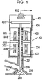
- Fig.1 in the accompanied drawings shows a general and schematic sectional view of an electro-magnetically driven intake valve, which is similarly shown in Fig. 2 of the Japanese Publication No. 2001-193504 based upon an application filed by the same applicant as the present application.
- an opening end of an inlet port 26 is fringed with a valve seat(s) 200 and opened and closed by a valve body 28a.
- the valve body 28a is carried by a valve shaft 28b, and in this figure, a valve guide 201 guides the valve shaft 28b so that the valve shaft can move up and down, and thereby, the valve body 28a is moved between opened and closed positions by electromagnetic driving apparatus generally denoted by 30.
- the electromagnetic driving apparatus 30 has a housing 300, within which incorporated are a valve-closing electromagnetic apparatus consisting of valve-closing cores 301 and valve-closing coils 303; a valve-opening electromagnetic apparatus consisting of valve-opening cores 302 and valve-opening coils 304; an armature 305 carried on the valve shaft 28b and movable between the valve-closing and valve-opening electromagnetic apparatuses; and compression coil springs 306 and 307. As shown in the drawing, the compression coil springs 306 and 307 bring the armature 305 to an intermediate position between the two electromagnetic apparatuses when neither of coils 303, 304 is energized.
- an intake valve lift sensor 40 is mounted directly on the electromagnetic driving apparatus 30.
- This lift sensor has a housing 400, mounted on the housing 300 of the electromagnetic driving apparatus 30; a disk-like target 401, mounted on the upper end of the valve shaft 28b within the housing 400; and a gap sensor 402 attached on the housing 400, while facing on the target 401, and detecting the displacement of the target.
- a slip joint is incorporated near the lower end of the valve shaft 28b, namely the coupling portion with the valve body 28a, which slip joint enables the distance between the valve body and armature to expand and contract very slightly.
- This slip joint is provided for avoiding a condition that, if the armature is fixedly connected to the valve body, the support of the armature flush against the valve-closing cores 301 and coils 303 would prevent the tight sealing of the valve body to the valve seat, when the valve body is forced on the valve seat by the pressure within a cylinder during compression and explosion strokes.
- valve-opening and/or valve-closing coils The control of operation of opening and closing this type of electro-magnetically driven valves is done by controlling energization of valve-opening and/or valve-closing coils.
- operational states of an electro-magnetically driven valve used for either of an intake valve or an exhaust valve, are either of an open state or a close state, and any states in between are transient unless any special control of opening and closing a valve is done.
- an electro-magnetically driven valve when operated, is held in either of a full opened position, in which an armature is adhered to an valve-opening electromagnet consisting of valve-opening coils and cores, or a full closed position, in which the armature is adhered to an valve-closing electromagnet consisting of valve-closing coils and cores, by feeding a weak holding current to the valve-opening or valve-closing coils except during opening or closing the valve.
- valve body When the valve body is moved from the full closed position to the full opened position, the holding current for the valve-closing coils is turned off first (usually, a reverse current is subsequently fed to the valve-closing coils), and then, under the action of springs, the valve body and armature start moving to the valve-opening side in unison. Thereafter, when the armature reaches to a position near an intermediate point between the valve-opening and valve-closing electromagnets and the distance between the armature and valve-opening electromagnet is shorten enough for the valve-opening electromagnet to function effectively through energization of the valve-opening coils, the energization of the valve-opening coil is started. Similarly, the valve is moved from the full opened position to the full closed position.
- the moving speeds of the valve body and armature is to be reduced to almost zero by the end of the opening or closing operation of the valve, for avoiding violent collision of the armature against the coils and cores of the valve-opening and/or closing electromagnets at the end of the opening or closing operation of the valve body; and violent collision of the valve body against a valve seat in closing the valve.
- the moving speeds of the valve body and armature are to be increased in the intermediate portion of the opening and closing movement of the valve.
- the moving speed of a valve body or an armature is preferably to be varied with the displacement of the valve body or armature as shown in Fig. 2.
- Fig. 2 an example of speed change in opening a valve is shown, wherein the abscissa is the displacement of a valve body or armature, namely Lift (the distance between the valve body and valve seat) and the ordinate is an opening speed, namely, the moving speed of the armature or valve body during opening.
- exciting current to be fed to coils (valve-opening coils in this case) is made varied with the position of the valve body or armature along a profile as shown in Fig. 3.
- the concepts defined as “distance”, “movement” and “speed” each have positive and negative values, and in matters of the opening and closing of a valve as in the present application, the distance, movement and speed are regarded as positive or negative, depending upon the direction of the movement of a valve body; but, since the present objects are to consider how opening and/or closing operations of a valve body are made quick and how the movement of the valve is terminated at the end of the operation without impact, the displacement of the valve body or armature, represented with lift as shown above, and the moving speed of the valve body or armature in the direction of increasing the displacement are defined as positive.
- exciting current fed to coils is controlled in connection with the displacement through combination of a feedforward(FF) control and a feedback (FB) control.
- the exciting current is controlled with the FF control for setting an actual moving speed for a target moving speed as shown in Fig. 2 (the profile in Fig.3).
- a deviation of an actual moving speed from the target, when generated, is (expectedly) cancelled by correcting the exciting current through the FB control based upon the value of the deviation.
- an amount of FB control for exciting current is given by -Gb ⁇ V, where Gb is a positive FB control gain.
- Gb is a positive FB control gain.
- an FB control gain Gb is constant, and in other cases as described in the above JP No. 2000-23454, an FB control gain is increased as the distance of spacing between an armature and an electromagnet attracting the armature (spacing distance) increases.
- JP No. 2002-81329 it is proposed to define fields in accordance with the ranges of deviation ⁇ V and spacing distance and to execute a feedback control using a different FB control gain for each of the fields.
- an FB control amount is given by - Gb ⁇ V as described above, it can be understood that, the larger the FB control gain is, the higher responsibility or sensitivity of the control, namely, the higher control speed is obtained, thereby increasing the effect of the FB control.
- the increase of the control speed however, often causes an excessive control inducing hunting in the control.
- an FB control gain is excessively small, the longer time would be required for making an actual moving speed in conformity with a target moving speed, or the moving speed at the end of the movement would not reach to the target moving speed that would be an appropriate value.
- the importance and/or necessity of FB control varies, dependent upon the relation between actual and target moving speeds, such as the direction and magnitude of the deviation between the actual and target moving speeds.
- a target moving speed is so set that the speed at the resting becomes substantially zero.
- an FB control gain should be set taking into account the necessity of FB control based upon the relation between actual and target moving speeds so as to avoid the control hunting and stepping-out condition.
- a target moving speed or an FF control amount (current fed to electromagnets If given in accordance with the profile in Fig.3) does not match characteristics of an actual electro-magnetically driven valve due to aging variation of the valve or an individual difference of products, and thereby, the magnitude (absolute value) of an FB control amount would be enlarged.
- a target moving speed and/or an FF control amount is predetermined values based upon the characteristics of an electro-magnetically driven valve, it is possible that the predetermined target moving speed would turn incompatible with the characteristics of an actual valve because the actual valve has a plurality of frictional sliding portions, electromagnets, springs, etc., the conditions and characteristics of which elements can vary from those at the manufacturing thereof.
- a target moving speed predetermined based upon designed characteristics can be incompatible with actual characteristics of a valve. Then, it would be difficult to make an actual moving speed in conformity with its target moving speed, resulting in the increase of the deviation ⁇ V and consequently, the increase of an FB control amount. This, in turn, would increase the fear of occurrence of the control hunting as described above. Accordingly, in order to reduce the fear of the hunting due to FB control and to make an actual moving speed in conformity with its target value quickly, it is preferable that a target moving speed and/or an FF control amount can be corrected, compensating for aging variation of an electro-magnetically driven valve and the other conditions thereof.
- a function determining (calculating) an FB control gain Gb is set out upon manufacturing or designing an electro-magnetically driven valve, it is possible that an FB control amount is insufficient to make an actual moving speed in conformity with its target moving speed because of aging variation and/or individual differences among products, as described above. Thus, it is preferable that a function and/or means for determining FB control gain Gb can be corrected appropriately after starting of use of an electro-magnetically driven valve.
- the objects of the present invention are to provide methods of controlling impulszation for improving the performance of an electro-magnetically driven valve operating as an intake or exhaust valve for an internal combustion engine, wherein, for increasing opening and closing speeds of the valve by increasing a control speed in the opening and closing control of the valve, there are taken into account that the importance of FB control varies dependent upon the relation between an actual moving speed and its target; and that there are the particular directional characteristics in the hunting and stepping-out limiting the gain of the FB control which consists in the whole control, as noted above; and also the effects of aging variation, etc. in the control of the electro-magnetically driven valve.
- the present invention provides a method of controlling energaization of an electro-magnetically driven valve having electromagnets and an armature which is attracted to the electromagnets and thereby moving a valve body to either of an opened position or a closed position, comprising: determining a target moving speed of the armature relative to the electromagnets dependent upon a spacing distance of the armature from the electromagnet; controlling at least a part of energization of the electro-magnetically driven valve through feedforward control so as to make an actual moving speed of the armature relative to the electromagnets in conformity with the target moving speed while controlling at least the other part of the energization through feedback control based upon a deviation of the actual moving speed from the target moving speed; in which a gain of the feedback control is changed based upon a relation between the actual moving speed and the target moving speed.
- the FB control gain may be smaller when a force of operational fluid that the electro-magnetically driven valve controls acts on the valve body in the same direction as the movement of the valve body than when a force of the operational fluid acts in the direction opposite to the movement of the valve body.
- the feedback control gain may be changed smaller when the actual moving speed is higher than the target moving speed than when the actual moving speed is lower than the target moving speed.
- the energization amount of the electromagnets may be shifted through learning modification so as to increase the moving speed for the spacing distance.
- the learning modification means modification of a current and future control based upon a result of an already executed control.
- the calculation of the FB control gain may be shifted to be increased through learning modification.
- the energization amount of the electromagnets may be shifted through learning modification so as to decrease the moving speed at least around the end of the movement.
- the feedback control gain may be controlled to vary continuously depending upon a deviation of an actual moving speed from a target moving speed.
- learning modification may be done in such a manner that a target moving speed of an armature is set out depending upon the spacing distance of the armature from an electromagnets; and then, the energization of an electro-magnetically driven valve is controlled so as to bring an actual moving speed of the armature relative to the electromagnets in conformity with the target moving speed, in which the setting of the target moving speed is modified through learning modification based upon a deviation of the actual moving speed from the target moving speed.
- a target moving speed of an armature relative to electromagnets is set out for a spacing distance of the armature relative to the electromagnets and the energization of the electromagnets is controlled so as to bring the actual moving speed in conformity with the target moving speed
- FB control where the energization of the electromagnets is corrected depending upon the deviation of the actual moving speed from the target moving speed
- the necessity of the FB control varies depending upon the relation between the actual moving speed and target moving speed. Accordingly, by setting the FB control gain based upon the relation between the actual moving speed and target moving speed, a more appropriate control of the moving speeds of the valve body and armature can be achieved.
- the FB control gain when the actual moving speed of the armature is lower than the target moving speed, the FB control gain will be set higher for bringing the actual moving speed close to the target moving speed, and on the other hand, when the actual moving speed is higher than the target moving speed, the FB control gain will be set smaller than that in the case that the actual moving speed of the armature is lower than the target moving speed, while avoiding the occurrence of the control hunting, and thereby it is allowed to bring the actual moving speed in conformity with the target moving speed while surely excluding the fear of the stepping-out in the opening and closing control of the electro-magnetically driven valve.
- a force of intake and/or exhaust flow acting on a valve body will help the action of electromagnets attracting an armature if the force is in the same direction as the movement of the valve body, but oppose the attraction of the electromagnets for the armature if the force is in the opposite direction to the movement of the valve body.
- the effect of the operational fluid can be eliminated from the energization control of the electro-magnetically valve through modification of an FB control gain depending upon the difference of the force impacted on the valve body from the operational fluid, in which modification the FB control gain is set smaller when a force of an operational fluid that the electro-magnetically driven valve controls acts on the valve body in the same direction as the movement of the valve body than when the force of the operational fluid acts in the opposite direction to the movement of the valve body.
- electromagnetic force must be increased by, for instance, applying a rather high holding current instantly the speed falls down to zero; otherwise, the armature would be pulled back to an intermediate point due to the action of springs, resulting in failure in adhesion of the armature, and possibly causing the above-mentioned stepping-out condition.
- the predetermined speed threshold is set as small as possible and within such a range that any control errors and/or control fluctuation could not render the actual moving speed fallen down to zero erroneously.
- the learning modification is also desired in a condition that an actual moving speed exceeds a target moving speed; the deviation of the actual moving speed from the target moving speed is not lower than a predetermined deviation threshold; and a final speed of the movement of the armature is also not lower than a predetermined speed threshold. It may be estimated that such a condition will occur because an energization amount fed to electromagnets for the target moving speed is too high.
- the learning modification is also desired in a condition that, although a deviation of an actual moving speed from a target moving speed is entirely at or below a predetermined deviation threshold, a final speed of the movement of the armature is at or above a predetermined speed threshold.
- Such an operational condition means that the setting of exciting current fed to coils is deviated to the higher speed side at the end of the movement.
- the energization amount fed to the electromagnets is shifted downwardly so as to reduce the moving speed at least at and around the end of the movement.
- an FB control amount in the direction of canceling the deviation ⁇ V will continuously vary without abrupt change and gradually increase and/or decrease depending upon the deviation ⁇ V Accordingly, not only the deviation ⁇ V will disappear more quickly, compared with the case of employing a constant FB control gain, but also the fear of occurrence of the control hunting will be reduced because of absence of an abrupt change in the FB control amount, which would be seen in a case of a stepwise changed FB control gain(in a certain case, it is possible that the sign of the FB control amount is reversed).
- Fig. 4A is a graph showing an embodiment according to the present invention, in which a target moving speed is set out for lift L during opening of a valve and a FB control gain Gb is reduced with the increase of the lift L, as illustrated in Fig. 2.
- a target moving speed is set out for lift L during opening of a valve and a FB control gain Gb is reduced with the increase of the lift L, as illustrated in Fig. 2.
- the increase of the lift L namely, as an armature is brought closer to electromagnets, its electromagnetic force is increased and the variation of an exciting current fed to coils more largely varies the electromagnetic force generated on the electromagnets.
- the FB control gain Gb is progressively reduced as the armature is brought closer to the electromagnets in order to avoid the occurrence of control hunting.
- the FB control gain Gb is set smaller in a case that a deviation ⁇ V of an actual moving speed of the armature relative to its target moving speed is positive ( ⁇ V>0) than in a case that ⁇ V is negative ( ⁇ V ⁇ 0).
- the FB control gain may be set as a constant, such as Gb ( ⁇ V ⁇ 0) and Gb ( ⁇ V>0) , where Gb ( ⁇ V ⁇ 0) > Gb ( ⁇ V>0) .
- the FB control gain Gb may be varied substantially continuously with the deviation ⁇ V, in order that the deviation ⁇ V may disappear while preventing the abrupt change and control hunting. Accordingly, the FB control gain may be given as a function of two parameters, lift L and deviation ⁇ V, which function decreases with the increase of the lift L (see curves in Fig. 4A and arrows in Fig. 4B) and varies depending upon the deviation ⁇ V (see arrows in Fig. 4A and Fig. 4B).
- the FB control gain Gb may be modified depending upon a force, applied to the valve body by operational fluid controlled by the valve, in which the FB control gain is set smaller when the force acts on the valve body in the same direction as its movement (P ⁇ 0) than when the force acts on the valve body in the direction opposite to its movement(P>0).
- the FB control gain is set smaller when the force acts on the valve body in the same direction as its movement (P ⁇ 0) than when the force acts on the valve body in the direction opposite to its movement(P>0).
- P its magnitude in each of the opposite signs may be taken into account, and the setting curve based upon ⁇ V may be modified dependent upon the value of P.
- Fig. 5 is a schematic diagram of a control system for implementing energization control of an electro-magnetically driven valve in an internal combustion engine of a vehicle in accordance with the present invention, but illustrating only elements relating to the control of the present invention.
- a control of the operation of the engine is executed with a vehicle operational control device.
- the vehicle operational control device 100 is a control device equipped with a microcomputer, to which fed are a signal indicating an accelerator opening from an accelerator opening sensor 1 which detects the depression of an accelerator pedal by a driver; a signal indicating an engine speed from an engine speed sensor 2; a signal indicating a vehicle speed from a vehicle speed sensor 3; a signal indicating a longitudinal acceleration of the vehicle from a longitudinal acceleration sensor 4; a signal indicating a temperature condition in the engine from an engine cooling water sensor 5; a signal indicating an angular position of a crank shaft from a crank shaft angular sensor 6; a signal indicating an intake valve opening from an intake valve lift sensor 7 (designated by 40 in the example of Fig.
- the vehicle operational control device 100 determines how to operate the engine every moment based upon the information, given from the above input signals relating to the operational conditions of the engine, and controls the operations of a throttling valve 9 provided in an intake passage of the engine; fuel injection valves 10, injecting fuel in intake air of the engine; an ignition coil 11 activating ignition plugs of the engine; coils 12 for closing the intake valve (designated by 303 in the example of Fig. 1); coils 13 for opening the intake valve (304 in Fig. 1); coils 14 for closing an exhaust valve; and coils for opening the exhaust valve.
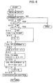
- Fig. 6 is a flowchart showing the whole control steps in the embodiment.
- step 10 When control starts in response to closure of an ignition switch, not shown in the drawings, data are read-in in step 10. Then, in step 20, it is judged whether or not the valve, the object to be controlled, should be opened, based upon the read-in data. If the answer is YES, the control goes to step 30, in which it is judged whether or not lift L of the valve has reached to the full opened lift Lo. Until the valve is fully opened, the answer will be NO, and thus the control will go to step 40.
- step 40 it is judged whether or not flag F1 is 1.
- flag F1 has been reset to 0 at the starting of the control
- the answer is NO at the first time the control reaches to this step after starting of the control, and thus, the control goes to step 50, in which calculated is a map, as illustrated in Fig. 2, defining the relation of lift L vs. target valve-opening speed Vt.
- the relation of lift L vs. target valve-opening speed Vt is calculated based upon a operational condition of the engine in every event of opening of an electro-magnetically driven valve, and the calculation is executed based upon the signals from the respective sensors as illustrated in Fig. 5.
- the setting of the map is executed, at the beginning, once for each of valve-opening events.
- step 70 current If, to be fed to the valve-opening coils as the amount of FF control in the total impulszation amount is calculated, based upon the map of lift L vs. target valve-opening speed Vt, set in the previous step and a map of lift L vs. exciting current as illustrated in Fig. 3. Then, the control goes to step 80.
- step 90 in which, based upon a judgment of the relation between the direction of operational fluid flow under the control of the vehicle operational control device as illustrated in Fig. 5 and the direction of the movement of the valve body (the sign of P in Fig. 4), FB control gain Gb for this moment is calculated using a function Gb (L, ⁇ V, P) employing the above parameters as variables.
- the function Gb(L, ⁇ V, P) in the calculation of the FB control gain is formed as shown in Figs.
- step 100 based upon the above-calculated deviation ⁇ V and FB control gain, current Ib, fed to the valve-opening coils as the amount of feedback control in the energization of the valve is calculated.
- ⁇ V>0 i.e. the actual moving speed of the armature is larger than its target moving speed
- the current component of FB control Ib reduces the exciting current fed to the coils by subtracting (the absolute value of) Gb ⁇ V from the current component If of the FF control.
- ⁇ V ⁇ 0 i.e. the actual moving speed of the armature is smaller than its target moving speed
- the current component of FB control Ib adds the absolute amount of Gb ⁇ V to the current component If of the FF control.
- the absolute value of Gb ⁇ V is larger when ⁇ V is negative than when ⁇ V is positive.
- step 120 current I, a sum of the current If, calculated as the current component of FF control, and the current Ib, calculated as the current component of FB control, is fed to the valve-opening coils.
- the current for the coils is rapidly raised up to a high value I1, held to the value I1 for a while, and subsequently, reduced gradually to a low value I2 as the valve is rendered closer to the full opened condition, and then fallen down to a holding current when the valve is fully opened.
- the reason why no current is fed in the initial phase of the opening of the valve is because, in this phase, the distance between the armature and electromagnet to be energized is too long for the electromagnetic force to effectively contribute to the movement of the valve. Accordingly, in the initial phase of opening of the valve, the armature is moved toward the full opened position under only the action of the springs. In the initial phase of opening of the valve, in the same way as the FF control, the FB control does not effectively contribute to the movement of the armature, either. Thus, the FB control may be set to start after the armature moves by a certain distance (it may be before the starting of feeding exciting current of the FF control).
- a higher degree of control can be achieved, in which a vibration system, consisting of the mass body including the armature, valve shaft connected thereto, valve body, etc. and springs, is rendered vibrating, and the valve is opened and closed more rapidly using electromagnets having smaller capacities, while, when the armature rests on the electromagnets in the end of the opening and/or closing event of the valve and/or when the valve body rests upon the valve seat in closing the valve, the moving speeds of the armature and valve body are brought as close to zero as possible.
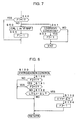
- step 51 the control goes to step 51 in the way of going from step 40 to step 50, i.e. upon the staring of the valve-opening operation in this example, and it is judged whether or not a condition for learning modification is established, i.e. whether or not the engine is operated under condition where the learning modification is allowed.
- step 52 in which flag F2 is set to 1.
- step 120 goes from step 120 to step 130 before returning to step 10, in which it is judged whether or not flag F2 is set to 1, and, if the answer is YES, the control goes to step 131, in which it is judged whether or not flag F3 is set to 1.
- Flag F3 will be set to 1 when the control goes to step 134 as described below.
- step 132 in which it is judged whether or not lift L reaches to Lo- ⁇ L, by ⁇ L before lift of the full opened position, Lo.
- ⁇ L is set to an appropriate value so as to grasp the entire deviation of the actual moving speed of the armature from its target moving speed, for example, the magnitude of 10 ⁇ 20 % of the full opened lift Lo. Until the answer in step 132 turns into YES, the control continues returning.
- step 132 When the answer in step 132 turns into YES, the control goes to step 133, in which the current deviation ⁇ V of the actual moving speed of the armature from its target moving speed is memorized as ⁇ Vo. Since, in this time, the control goes to step 134 in which flag F3 is set to 1, the control after this goes from step 131 to Return while bypassing step 132.
- step 30 When the valve reaches to the full opened position because of the advance of the control according to the flowchart of Fig. 6 and the answer of step 30 becomes YES, the control goes to step 31 as shown in Fig. 9, in which it is judged whether or not flag F2 is set to 1. If the learning condition is not established, the answer is NO and the control terminates.
- step 32 When F2 has been set to 1, the control goes to step 32, in which it is judged whether or not the final value Ve of the actual moving speed of the armature is at or above a predetermined speed threshold Va.
- step 33 In which it is judged whether or not the deviation ⁇ Vo memorized previously in step 133 is at or above a predetermined deviation threshold ⁇ Vb. If the answer is YES, the control goes to step 34.
- the control reaches to this step, the deviation of the actual moving speed of the armature from the target moving speed is not lower than the predetermined deviation threshold, and the final speed of the movement of the armature is not lower than the predetermined speed threshold.
- learning modification of the function Gb(L, ⁇ V, P) for calculating the FB control gain is executed so as to increase the FB control gain.
- step 35 When the answer in step 33 is NO, the control goes to step 35.
- the control reaches to this step, the deviation of the actual moving speed of the armature from its target moving speed is entirely lower than the predetermined deviation threshold but the final speed of the movement of the armature is not lower than the predetermined speed threshold.
- step 35 the map of lift L vs. exciting current If (Fig. 3) is shifted through the learning modification based upon the final speed Ve of the movement of the armature so as to reduce the FF control amount and thereby decreasing the moving speed at least around the end of the movement.
- learning modification of the map of lift L vs. target valve-opening speed Vt as shown in Fig. 2 may be executed, which will render the speed control more preciser and smoother.
- step 36 the control goes to step 36.
- the control reaches to this step, the final value of the actual moving speed of the armature is lower than the predetermined speed threshold.
- step 36 the map of lift L vs. exciting current is shifted through learning modification based upon the final speed Ve of the movement of the armature so as to increase the FF control amount for increasing the moving speed at least around the end of the movement.
- the learning modification may be executed for the map of lift L vs. target valve-opening speed Vt in step 36, which will render the speed control more preciser and smoother.
- Figs. 6 ⁇ 9 show the control in opening the valve from the closed position
- the control in closing the valve from the opened position may be executed in substantially similar manners with non-substantial changes, such as replacing the judgment for opening the valve with the one for closing the valve, defining lift L as a moving distance from the full opened position to the full closed position, etc.
Landscapes
- Engineering & Computer Science (AREA)
- General Engineering & Computer Science (AREA)
- Mechanical Engineering (AREA)
- Physics & Mathematics (AREA)
- Electromagnetism (AREA)
- Chemical & Material Sciences (AREA)
- Combustion & Propulsion (AREA)
- Valve Device For Special Equipments (AREA)
- Output Control And Ontrol Of Special Type Engine (AREA)
- Magnetically Actuated Valves (AREA)
- Feedback Control In General (AREA)
Abstract
A control method with variable feedback gain for energization of an electro-magnetically
driven intake/exhaust valve of an internal combustion engine
increases opening and closing speeds of the intake/exhaust valve driven with
electromagnets having small capacity and improves the control performance
in bringing the final speed of the opening and closing action of the valve close
to zero. According to the variable feedback gain energization control
method, a target moving speed of the armature relative to the
electromagnets is determined dependent upon a spacing distance of the
armature from the electromagnet; at least a part of energization of the
electro-magnetically driven valve is controlled through feedforward control
so as to make an actual moving speed of the armature relative to the
electromagnets in conformity with the target moving speed while at least the
other part of the energization is controlled through feedback control based
upon a deviation of the actual moving speed from the target moving speed.
And a gain of the feedback control is changed based upon a relation between
the actual moving speed and the target moving speed. The energization
control is modified through learning modification based upon the deviation
between the actual and target moving speeds and the actual value of the
final speed of opening and closing the valve.
Description
This invention relates to methods of controlling energization of an
electro-magnetically driven valve such as an intake valve and an exhaust
valve in an internal combustion engine.
With the recent development of computer control technologies, in the
field of internal combustion engines, especially for a vehicle, an electro-magnetic
actuator has been employed for opening and closing an intake
valve and/or an exhaust valve, instead of a conventional cam on a cam shaft
driven synchronously with a crank shaft, and, based upon the increase of the
degree of freedom of the timing of the opening and closing operations of the
valves through use of the electro-magnetic actuator, there have been
proposed various manners of controlling the operation of an internal
combustion engine. Examples of such operation controls are described in
Japanese Patent Laid-Open publications Nos. 11-210916, 2000-73800, 2000-234534,
2000-337177, 2001-182570, 2001-193504, 2002-81329, 2002-81569.
Fig.1 in the accompanied drawings shows a general and schematic
sectional view of an electro-magnetically driven intake valve, which is
similarly shown in Fig. 2 of the Japanese Publication No. 2001-193504 based
upon an application filed by the same applicant as the present application.
In this drawing, an opening end of an inlet port 26 is fringed with a valve
seat(s) 200 and opened and closed by a valve body 28a. The valve body 28a
is carried by a valve shaft 28b, and in this figure, a valve guide 201 guides
the valve shaft 28b so that the valve shaft can move up and down, and
thereby, the valve body 28a is moved between opened and closed positions by
electromagnetic driving apparatus generally denoted by 30.
The electromagnetic driving apparatus 30 has a housing 300, within
which incorporated are a valve-closing electromagnetic apparatus consisting
of valve-closing cores 301 and valve-closing coils 303; a valve-opening
electromagnetic apparatus consisting of valve-opening cores 302 and valve-opening
coils 304; an armature 305 carried on the valve shaft 28b and
movable between the valve-closing and valve-opening electromagnetic
apparatuses; and compression coil springs 306 and 307. As shown in the
drawing, the compression coil springs 306 and 307 bring the armature 305 to
an intermediate position between the two electromagnetic apparatuses when
neither of coils 303, 304 is energized.
In the example as shown here, an intake valve lift sensor 40 is
mounted directly on the electromagnetic driving apparatus 30. This lift
sensor has a housing 400, mounted on the housing 300 of the electromagnetic
driving apparatus 30; a disk-like target 401, mounted on the upper end of the
valve shaft 28b within the housing 400; and a gap sensor 402 attached on the
housing 400, while facing on the target 401, and detecting the displacement
of the target.
Further, although not shown in the drawing, in such an electro-magnetically
driven valve used as intake and/or exhaust valves, in general, a
slip joint is incorporated near the lower end of the valve shaft 28b, namely
the coupling portion with the valve body 28a, which slip joint enables the
distance between the valve body and armature to expand and contract very
slightly. This slip joint is provided for avoiding a condition that, if the
armature is fixedly connected to the valve body, the support of the armature
flush against the valve-closing cores 301 and coils 303 would prevent the
tight sealing of the valve body to the valve seat, when the valve body is
forced on the valve seat by the pressure within a cylinder during
compression and explosion strokes.
The control of operation of opening and closing this type of electro-magnetically
driven valves is done by controlling energization of valve-opening
and/or valve-closing coils. In this case, generally, the operational
states of an electro-magnetically driven valve, used for either of an intake
valve or an exhaust valve, are either of an open state or a close state, and any
states in between are transient unless any special control of opening and
closing a valve is done. Thus, usually, an electro-magnetically driven valve,
when operated, is held in either of a full opened position, in which an
armature is adhered to an valve-opening electromagnet consisting of valve-opening
coils and cores, or a full closed position, in which the armature is
adhered to an valve-closing electromagnet consisting of valve-closing coils
and cores, by feeding a weak holding current to the valve-opening or valve-closing
coils except during opening or closing the valve. When the valve
body is moved from the full closed position to the full opened position, the
holding current for the valve-closing coils is turned off first (usually, a
reverse current is subsequently fed to the valve-closing coils), and then,
under the action of springs, the valve body and armature start moving to the
valve-opening side in unison. Thereafter, when the armature reaches to a
position near an intermediate point between the valve-opening and valve-closing
electromagnets and the distance between the armature and valve-opening
electromagnet is shorten enough for the valve-opening
electromagnet to function effectively through energization of the valve-opening
coils, the energization of the valve-opening coil is started.
Similarly, the valve is moved from the full opened position to the full closed
position.
In general, when a valve body is started to move from a full closed
position to a full opened position or from the full opened position to the full
closed position, its moving speed increases gradually together with its
displacement (Usually, as an armature moves closer to an electromagnet, its
electromagnetic force attracting the armature increases.). Preferably,
however, the moving speeds of the valve body and armature is to be reduced
to almost zero by the end of the opening or closing operation of the valve, for
avoiding violent collision of the armature against the coils and cores of the
valve-opening and/or closing electromagnets at the end of the opening or
closing operation of the valve body; and violent collision of the valve body
against a valve seat in closing the valve. On the other hand, in order to
complete the opening and closing operation of the valve quickly, preferably,
the moving speeds of the valve body and armature are to be increased in the
intermediate portion of the opening and closing movement of the valve.
From the above, it is generally recognized that the moving speed of a
valve body or an armature is preferably to be varied with the displacement of
the valve body or armature as shown in Fig. 2. In Fig. 2, an example of
speed change in opening a valve is shown, wherein the abscissa is the
displacement of a valve body or armature, namely Lift (the distance between
the valve body and valve seat) and the ordinate is an opening speed, namely,
the moving speed of the armature or valve body during opening. For
varying the moving speed with lift as shown in Fig. 2, exciting current to be
fed to coils (valve-opening coils in this case) is made varied with the position
of the valve body or armature along a profile as shown in Fig. 3.
In this connection, mathematically speaking, the concepts defined as
"distance", "movement" and "speed" each have positive and negative values,
and in matters of the opening and closing of a valve as in the present
application, the distance, movement and speed are regarded as positive or
negative, depending upon the direction of the movement of a valve body; but,
since the present objects are to consider how opening and/or closing
operations of a valve body are made quick and how the movement of the
valve is terminated at the end of the operation without impact, the
displacement of the valve body or armature, represented with lift as shown
above, and the moving speed of the valve body or armature in the direction of
increasing the displacement are defined as positive.
Furthermore, in order to obtain the relation between the
displacement and moving speed of a valve body or an armature as shown in
Fig.2, exciting current fed to coils is controlled in connection with the
displacement through combination of a feedforward(FF) control and a
feedback (FB) control. In this case, first, the exciting current is controlled
with the FF control for setting an actual moving speed for a target moving
speed as shown in Fig. 2 (the profile in Fig.3). A deviation of an actual
moving speed from the target, when generated, is (expectedly) cancelled by
correcting the exciting current through the FB control based upon the value
of the deviation. Usually, based upon a deviation of an actual moving speed
V from a target moving speed Vt, ΔV (= V - Vt), an amount of FB control for
exciting current is given by -Gb·ΔV, where Gb is a positive FB control gain.
Thus, when ΔV is positive, namely, when the actual moving speed exceeds
the target moving speed, the control of the exciting current is done by
subtracting Gb·ΔV from the corresponding FF control amount. In one case,
an FB control gain Gb is constant, and in other cases as described in the
above JP No. 2000-23454, an FB control gain is increased as the distance of
spacing between an armature and an electromagnet attracting the armature
(spacing distance) increases. In JP No. 2002-81329, it is proposed to define
fields in accordance with the ranges of deviation ΔV and spacing distance
and to execute a feedback control using a different FB control gain for each of
the fields.
By the way, since an FB control amount is given by - Gb·ΔV as
described above, it can be understood that, the larger the FB control gain is,
the higher responsibility or sensitivity of the control, namely, the higher
control speed is obtained, thereby increasing the effect of the FB control.
The increase of the control speed, however, often causes an excessive control
inducing hunting in the control. On the other hand, if an FB control gain is
excessively small, the longer time would be required for making an actual
moving speed in conformity with a target moving speed, or the moving speed
at the end of the movement would not reach to the target moving speed that
would be an appropriate value.
Further, in the speed control of the opening and closing operation of
an electro-magnetically driven valve: the controlled object of the present
invention, the importance and/or necessity of FB control varies, dependent
upon the relation between actual and target moving speeds, such as the
direction and magnitude of the deviation between the actual and target
moving speeds. As already described, in order to prevent violent collision
between a valve seat or an electromagnet and a valve body or an armature
resting thereon (at the end of an opening or closing operation), a target
moving speed is so set that the speed at the resting becomes substantially
zero. For example, however, in a case that an actual moving speed exceeds
its target value, it is enough that the speed at the resting is within a certain
satisfactory range and there is little need to urgently correct the actual
moving speed through FB control (it is possible that the reduction in the time
for opening and closing a valve is preferable.). On the other hand, when an
actual moving speed is lower than its target one, it is possible that the
moving speed has become zero before an armature reaches to electromagnets.
In this case, the armature will be pulled back by springs, and thereby, the
armature and a valve body are floating around the intermediate position
between opened and closed positions, inducing a very serious problem of
stepping-out of operation of an intake valve or an exhaust valve. In order to
avoid such a stepping-out condition, it is required that an actual moving
speed can be corrected quickly through FB control without inducing the
control hunting.
Accordingly, in the control of opening and closing speed of an electro-magnetically
driven valve, an FB control gain should be set taking into
account the necessity of FB control based upon the relation between actual
and target moving speeds so as to avoid the control hunting and stepping-out
condition.
Further, it is possible that a target moving speed or an FF control
amount (current fed to electromagnets If given in accordance with the profile
in Fig.3) does not match characteristics of an actual electro-magnetically
driven valve due to aging variation of the valve or an individual difference of
products, and thereby, the magnitude (absolute value) of an FB control
amount would be enlarged. In other words, while a target moving speed
and/or an FF control amount is predetermined values based upon the
characteristics of an electro-magnetically driven valve, it is possible that the
predetermined target moving speed would turn incompatible with the
characteristics of an actual valve because the actual valve has a plurality of
frictional sliding portions, electromagnets, springs, etc., the conditions and
characteristics of which elements can vary from those at the manufacturing
thereof. Also, in actual products, some differences of performances among
the products are inevitable so that a target moving speed predetermined
based upon designed characteristics can be incompatible with actual
characteristics of a valve. Then, it would be difficult to make an actual
moving speed in conformity with its target moving speed, resulting in the
increase of the deviation ΔV and consequently, the increase of an FB control
amount. This, in turn, would increase the fear of occurrence of the control
hunting as described above. Accordingly, in order to reduce the fear of the
hunting due to FB control and to make an actual moving speed in conformity
with its target value quickly, it is preferable that a target moving speed
and/or an FF control amount can be corrected, compensating for aging
variation of an electro-magnetically driven valve and the other conditions
thereof.
Further, while a function determining (calculating) an FB control
gain Gb is set out upon manufacturing or designing an electro-magnetically
driven valve, it is possible that an FB control amount is insufficient to make
an actual moving speed in conformity with its target moving speed because
of aging variation and/or individual differences among products, as described
above. Thus, it is preferable that a function and/or means for determining
FB control gain Gb can be corrected appropriately after starting of use of an
electro-magnetically driven valve.
Moreover, during use of an internal combustion engine,
intake/exhaust valves are directly exposed to pressure variation of
operational fluid in cylinders, and thus, the movements of valve bodies are
subject to acceleration and deceleration forces from the operational fluid.
Acceleration and deceleration forces are advanced by first order from a
moving speed to be controlled, and accordingly, are not directly reflected in
- Gb·ΔV. Thus, more appropriate speed control will be achieved if effect of
pressure of operational fluid is taken into account in control of an FB control
gain.
Furthermore, as already noted, in the energization control for
electro-magnetically driven valves described in some of the above-listed
patent publications, it has been proposed to selectively and appropriately
employ different FB control gains depending upon the distance between an
armature and (energized) electromagnets or deviation (ΔV) between an
actual moving speed and a target moving speed, rather than an always
constant FB control gain. In order to avoid the control hunting and/or
stepping-out of control, however, it is desirable that deviation ΔV or else is
corrected quickly and gently without abrupt change of an FB control gain.
The objects of the present invention are to provide methods of
controlling energiazation for improving the performance of an electro-magnetically
driven valve operating as an intake or exhaust valve for an
internal combustion engine, wherein, for increasing opening and closing
speeds of the valve by increasing a control speed in the opening and closing
control of the valve, there are taken into account that the importance of FB
control varies dependent upon the relation between an actual moving speed
and its target; and that there are the particular directional characteristics in
the hunting and stepping-out limiting the gain of the FB control which
consists in the whole control, as noted above; and also the effects of aging
variation, etc. in the control of the electro-magnetically driven valve.
For achieving the above-mentioned object, the present invention
provides a method of controlling energaization of an electro-magnetically
driven valve having electromagnets and an armature which is attracted to
the electromagnets and thereby moving a valve body to either of an opened
position or a closed position, comprising: determining a target moving speed
of the armature relative to the electromagnets dependent upon a spacing
distance of the armature from the electromagnet; controlling at least a part
of energization of the electro-magnetically driven valve through feedforward
control so as to make an actual moving speed of the armature relative to the
electromagnets in conformity with the target moving speed while controlling
at least the other part of the energization through feedback control based
upon a deviation of the actual moving speed from the target moving speed; in
which a gain of the feedback control is changed based upon a relation
between the actual moving speed and the target moving speed.
In the above-described energization control method of the electro-magnetically
driven valve, the FB control gain may be smaller when a force
of operational fluid that the electro-magnetically driven valve controls acts
on the valve body in the same direction as the movement of the valve body
than when a force of the operational fluid acts in the direction opposite to the
movement of the valve body.
In the above-described energization control method of the electro-magnetically
driven valve, the feedback control gain may be changed smaller
when the actual moving speed is higher than the target moving speed than
when the actual moving speed is lower than the target moving speed.
Further, when a final value of the actual moving speed (a resting
speed) is smaller than a predetermined speed threshold, the energization
amount of the electromagnets may be shifted through learning modification
so as to increase the moving speed for the spacing distance. Here, the
learning modification means modification of a current and future control
based upon a result of an already executed control.
Furthermore, when a deviation of an actual moving speed from a
target moving speed is not lower than a predetermined deviation threshold
and a final speed of the movement of the armature is not lower than a
predetermined speed threshold, the calculation of the FB control gain may be
shifted to be increased through learning modification.
Moreover, when a deviation of an actual moving speed from a target
moving speed is entirely not higher than a predetermined deviation
threshold but a final speed of the movement of the armature is not lower
than a predetermined speed threshold, the energization amount of the
electromagnets may be shifted through learning modification so as to
decrease the moving speed at least around the end of the movement.
Also, the feedback control gain may be controlled to vary
continuously depending upon a deviation of an actual moving speed from a
target moving speed.
In this connection, learning modification may be done in such a
manner that a target moving speed of an armature is set out depending upon
the spacing distance of the armature from an electromagnets; and then, the
energization of an electro-magnetically driven valve is controlled so as to
bring an actual moving speed of the armature relative to the electromagnets
in conformity with the target moving speed, in which the setting of the target
moving speed is modified through learning modification based upon a
deviation of the actual moving speed from the target moving speed.
As described above, in a control of energization of an electro-magnetically
driven valve including FF control, where a target moving speed
of an armature relative to electromagnets is set out for a spacing distance of
the armature relative to the electromagnets and the energization of the
electromagnets is controlled so as to bring the actual moving speed in
conformity with the target moving speed, and FB control, where the
energization of the electromagnets is corrected depending upon the deviation
of the actual moving speed from the target moving speed, the necessity of the
FB control varies depending upon the relation between the actual moving
speed and target moving speed. Accordingly, by setting the FB control gain
based upon the relation between the actual moving speed and target moving
speed, a more appropriate control of the moving speeds of the valve body and
armature can be achieved.
In particular, as already noted, since the risk of occurrence of the
stepping-out condition is higher when an actual moving speed of an
armature is lower than its target moving speed (ΔV < 0) than when the
actual moving speed is higher than its target moving speed (ΔV>0), even if
the absolute values of the deviations of the actual moving speed from the
target moving speed in both the cases are equal to each other, it is required
in the former case to increase the moving speed as quickly as possible.
Thus, when the actual moving speed of the armature is lower than the target
moving speed, the FB control gain will be set higher for bringing the actual
moving speed close to the target moving speed, and on the other hand, when
the actual moving speed is higher than the target moving speed, the FB
control gain will be set smaller than that in the case that the actual moving
speed of the armature is lower than the target moving speed, while avoiding
the occurrence of the control hunting, and thereby it is allowed to bring the
actual moving speed in conformity with the target moving speed while surely
excluding the fear of the stepping-out in the opening and closing control of
the electro-magnetically driven valve.
Further, as already noted, a force of intake and/or exhaust flow
acting on a valve body will help the action of electromagnets attracting an
armature if the force is in the same direction as the movement of the valve
body, but oppose the attraction of the electromagnets for the armature if the
force is in the opposite direction to the movement of the valve body. Thus,
the effect of the operational fluid can be eliminated from the energization
control of the electro-magnetically valve through modification of an FB
control gain depending upon the difference of the force impacted on the valve
body from the operational fluid, in which modification the FB control gain is
set smaller when a force of an operational fluid that the electro-magnetically
driven valve controls acts on the valve body in the same direction as the
movement of the valve body than when the force of the operational fluid acts
in the opposite direction to the movement of the valve body.
Also, the problem that characteristics of an actual electro-magnetically
driven valve turn to be incompatible with predetermined FF
control and/or FB control can be solved through learning modification of
control amounts, namely modifying current and future operation based upon
results of past operation automatically and anytime in each of products.
One of important matters to be modified through such learning
modification is that, with reference to the graph of opening speed vs. lift as
shown in Fig. 2, the curve of an actual movement of an armature at and
around its end should not fall below the target curve (In Fig.2, although the
resting speed (at full opened position) is shown as substantially zero, the
armature in practical contacts the electromagnets at a low speed within a
range of inducing no damage on electromagnets). If the curve of the actual
moving speed of the armature around its end falls below the target curve, the
possibility that the speed becomes substantially zero before the armature
reaches to the point of full opening would increase. In this case,
electromagnetic force must be increased by, for instance, applying a rather
high holding current instantly the speed falls down to zero; otherwise, the
armature would be pulled back to an intermediate point due to the action of
springs, resulting in failure in adhesion of the armature, and possibly
causing the above-mentioned stepping-out condition.
Thus, as described above, through learning modification where an
energization amount fed to electromagnets is shifted so as to increase a
moving speed when a final value of an actual speed is smaller than a
predetermined speed threshold, the final value of the actual moving speed is
always maintained at or above a predetermined speed threshold, and
thereby it can be avoided that the actual moving speed falls to zero before
reaching the full opening point. In this case, it is enough that the
predetermined speed threshold is set as small as possible and within such a
range that any control errors and/or control fluctuation could not render the
actual moving speed fallen down to zero erroneously.
The learning modification is also desired in a condition that an actual
moving speed exceeds a target moving speed; the deviation of the actual
moving speed from the target moving speed is not lower than a
predetermined deviation threshold; and a final speed of the movement of the
armature is also not lower than a predetermined speed threshold. It may
be estimated that such a condition will occur because an energization
amount fed to electromagnets for the target moving speed is too high. In
such a condition, through modifying a function of calculating an FB control
gain so as to increase the FB control gain; reducing the energization amount
fed to the electromagnets; and modifying downwardly the actual moving
speed relative to the target moving speed over the whole movement, it can be
simultaneously overcome that both the problems that the actual moving
speed would increase relative to the target moving speed and that the final
speed of the movement of the armature is too high.
Further, the learning modification is also desired in a condition that,
although a deviation of an actual moving speed from a target moving speed is
entirely at or below a predetermined deviation threshold, a final speed of the
movement of the armature is at or above a predetermined speed threshold.
Such an operational condition means that the setting of exciting current fed
to coils is deviated to the higher speed side at the end of the movement.
Thus, in such a condition, through learning modification, the energization
amount fed to the electromagnets is shifted downwardly so as to reduce the
moving speed at least at and around the end of the movement.
Moreover, when a FB control gain is substantially continuously
changed depending upon a deviation ΔV, an FB control amount in the
direction of canceling the deviation ΔV will continuously vary without abrupt
change and gradually increase and/or decrease depending upon the deviation
ΔV Accordingly, not only the deviation ΔV will disappear more quickly,
compared with the case of employing a constant FB control gain, but also the
fear of occurrence of the control hunting will be reduced because of absence of
an abrupt change in the FB control amount, which would be seen in a case of
a stepwise changed FB control gain(in a certain case, it is possible that the
sign of the FB control amount is reversed).
Fig. 4A is a graph showing an embodiment according to the present
invention, in which a target moving speed is set out for lift L during opening
of a valve and a FB control gain Gb is reduced with the increase of the lift L,
as illustrated in Fig. 2. As already noted, together with the increase of the
lift L, namely, as an armature is brought closer to electromagnets, its
electromagnetic force is increased and the variation of an exciting current
fed to coils more largely varies the electromagnetic force generated on the
electromagnets. Accordingly, as the armature is brought closer to the
electromagnets, a contribution of an FB control amount to the
electromagnetic force or the moving speed of the armature is increased, and
therefore, as shown in Fig. 4A, it is preferable that the FB control gain Gb is
progressively reduced as the armature is brought closer to the
electromagnets in order to avoid the occurrence of control hunting.
Further, as seen from this figure, the FB control gain Gb is set
smaller in a case that a deviation ΔV of an actual moving speed of the
armature relative to its target moving speed is positive (ΔV>0) than in a case
that ΔV is negative (ΔV<0). In this regard, in each case of ΔV>0 and ΔV<0,
the FB control gain may be set as a constant, such as Gb(ΔV<0) and Gb(ΔV>0),
where Gb(ΔV<0) > Gb(ΔV>0). In this case, since ΔV=0 upon the switching of the
FB control gain, no abrupt change of the FB control amount due to the
switching of the FB control gain occurs substantially. However, for
canceling the deviation ΔV, the FB control gain Gb may be varied
substantially continuously with the deviation ΔV, in order that the deviation
ΔV may disappear while preventing the abrupt change and control hunting.
Accordingly, the FB control gain may be given as a function of two
parameters, lift L and deviation ΔV, which function decreases with the
increase of the lift L (see curves in Fig. 4A and arrows in Fig. 4B) and varies
depending upon the deviation ΔV (see arrows in Fig. 4A and Fig. 4B).
Moreover, in the illustrated embodiment, the FB control gain Gb may
be modified depending upon a force, applied to the valve body by operational
fluid controlled by the valve, in which the FB control gain is set smaller
when the force acts on the valve body in the same direction as its movement
(P<0) than when the force acts on the valve body in the direction opposite to
its movement(P>0). In this connection, with respect to P, its magnitude in
each of the opposite signs may be taken into account, and the setting curve
based upon ΔV may be modified dependent upon the value of P.
Fig. 5 is a schematic diagram of a control system for implementing
energization control of an electro-magnetically driven valve in an internal
combustion engine of a vehicle in accordance with the present invention, but
illustrating only elements relating to the control of the present invention.
In this internal combustion engine for a vehicle, a control of the operation of
the engine is executed with a vehicle operational control device. In the
diagram, the vehicle operational control device 100 is a control device
equipped with a microcomputer, to which fed are a signal indicating an
accelerator opening from an accelerator opening sensor 1 which detects the
depression of an accelerator pedal by a driver; a signal indicating an engine
speed from an engine speed sensor 2; a signal indicating a vehicle speed from
a vehicle speed sensor 3; a signal indicating a longitudinal acceleration of the
vehicle from a longitudinal acceleration sensor 4; a signal indicating a
temperature condition in the engine from an engine cooling water sensor 5; a
signal indicating an angular position of a crank shaft from a crank shaft
angular sensor 6; a signal indicating an intake valve opening from an intake
valve lift sensor 7 (designated by 40 in the example of Fig. 1); and a signal
indicating an exhaust valve opening from an exhaust valve lift sensor 8.
The vehicle operational control device 100 determines how to operate the
engine every moment based upon the information, given from the above
input signals relating to the operational conditions of the engine, and
controls the operations of a throttling valve 9 provided in an intake passage
of the engine; fuel injection valves 10, injecting fuel in intake air of the
engine; an ignition coil 11 activating ignition plugs of the engine; coils 12 for
closing the intake valve (designated by 303 in the example of Fig. 1); coils 13
for opening the intake valve (304 in Fig. 1); coils 14 for closing an exhaust
valve; and coils for opening the exhaust valve.
In the followings, a way of executing a method of controlling
energization of an electro-magnetically driven valve according to the present
invention with a vehicle operational control device as shown in Fig. 5 will be
more in detail explained with respect to one of its embodiments. Fig. 6 is a
flowchart showing the whole control steps in the embodiment.
When control starts in response to closure of an ignition switch, not
shown in the drawings, data are read-in in step 10. Then, in step 20, it is
judged whether or not the valve, the object to be controlled, should be opened,
based upon the read-in data. If the answer is YES, the control goes to step 30,
in which it is judged whether or not lift L of the valve has reached to the full
opened lift Lo. Until the valve is fully opened, the answer will be NO, and
thus the control will go to step 40.
In step 40, it is judged whether or not flag F1 is 1. In this type of
control, since flag F1 has been reset to 0 at the starting of the control, the
answer is NO at the first time the control reaches to this step after starting
of the control, and thus, the control goes to step 50, in which calculated is a
map, as illustrated in Fig. 2, defining the relation of lift L vs. target valve-opening
speed Vt. In this connection, the relation of lift L vs. target valve-opening
speed Vt is calculated based upon a operational condition of the
engine in every event of opening of an electro-magnetically driven valve, and
the calculation is executed based upon the signals from the respective
sensors as illustrated in Fig. 5. In this embodiment, since the judgment of
flag F1 in step 40 and the setting of flag F1 to 1 in step 60 are executed, the
setting of the map is executed, at the beginning, once for each of valve-opening
events.
When the control reaches to step 70, current If, to be fed to the
valve-opening coils as the amount of FF control in the total energiazation
amount is calculated, based upon the map of lift L vs. target valve-opening
speed Vt, set in the previous step and a map of lift L vs. exciting current as
illustrated in Fig. 3. Then, the control goes to step 80.
In step 80, a valve-opening speed V at a moment in each flow is
compared with a target valve-opening speed Vt at the corresponding moment,
and the difference between them ΔV= V - Vt is calculated.
Next, the control goes to step 90, in which, based upon a judgment of
the relation between the direction of operational fluid flow under the control
of the vehicle operational control device as illustrated in Fig. 5 and the
direction of the movement of the valve body (the sign of P in Fig. 4), FB
control gain Gb for this moment is calculated using a function Gb (L, ΔV, P)
employing the above parameters as variables. The function Gb(L, ΔV, P) in
the calculation of the FB control gain is formed as shown in Figs. 4A or 4B,
rendering the FB control gain larger for larger distance between the
armature and electromagnets attracting it (=Lo-L), and further, calculating
the FB control gain which varies depending upon ΔV and P in the above-mentioned
manner.
Then, in step 100, based upon the above-calculated deviation ΔV and
FB control gain, current Ib, fed to the valve-opening coils as the amount of
feedback control in the energization of the valve is calculated. Gb is defined
as positive, so that Ib is calculated by Ib = - Gb·ΔV.
In the next step 110, the energization value for the valve-opening
coils is calculated by I=If +Ib. When ΔV>0, i.e. the actual moving speed of
the armature is larger than its target moving speed, the current component
of FB control Ib reduces the exciting current fed to the coils by subtracting
(the absolute value of) Gb·ΔV from the current component If of the FF control.
On the other hand, when ΔV<0, i.e. the actual moving speed of the armature
is smaller than its target moving speed, the current component of FB control
Ib adds the absolute amount of Gb·ΔV to the current component If of the FF
control. As explained above, the absolute value of Gb·ΔV is larger when ΔV
is negative than when ΔV is positive.
Subsequently, in step 120, current I, a sum of the current If,
calculated as the current component of FF control, and the current Ib,
calculated as the current component of FB control, is fed to the valve-opening
coils. In this connection, in the example of the energization pattern of
opening the valve based upon the FF control as illustrated in Fig.3, when the
valve is opened to about one-third of a full opened condition, the current for
the coils is rapidly raised up to a high value I1, held to the value I1 for a
while, and subsequently, reduced gradually to a low value I2 as the valve is
rendered closer to the full opened condition, and then fallen down to a
holding current when the valve is fully opened. The reason why no current
is fed in the initial phase of the opening of the valve is because, in this phase,
the distance between the armature and electromagnet to be energized is too
long for the electromagnetic force to effectively contribute to the movement of
the valve. Accordingly, in the initial phase of opening of the valve, the
armature is moved toward the full opened position under only the action of
the springs. In the initial phase of opening of the valve, in the same way as
the FF control, the FB control does not effectively contribute to the
movement of the armature, either. Thus, the FB control may be set to start
after the armature moves by a certain distance (it may be before the starting
of feeding exciting current of the FF control).
In accordance with the above-described manners, a higher degree of
control can be achieved, in which a vibration system, consisting of the mass
body including the armature, valve shaft connected thereto, valve body, etc.
and springs, is rendered vibrating, and the valve is opened and closed more
rapidly using electromagnets having smaller capacities, while, when the
armature rests on the electromagnets in the end of the opening and/or
closing event of the valve and/or when the valve body rests upon the valve
seat in closing the valve, the moving speeds of the armature and valve body
are brought as close to zero as possible.
Next, referring to Figs. 7, 8 and 9, there is explained about an
embodiment incorporating a function of learning modification as described
above by modifying a part of the flowchart in Fig. 6.
For executing learning modification, first, as shown in Fig.7, the
control goes to step 51 in the way of going from step 40 to step 50, i.e. upon
the staring of the valve-opening operation in this example, and it is judged
whether or not a condition for learning modification is established, i.e.
whether or not the engine is operated under condition where the learning
modification is allowed. Conditions that the operation of the engine is not
subject to the effect of the accelerator opening and the force imparted on the
valve body from operational fluid is constant, such as just before stopping the
engine, during fuel cut-off, upon starting of the engine, etc., may be
considered as satisfying conditions for the learning modification. Then,
when the answer is YES, the control goes to step 52, in which flag F2 is set to
1.
Subsequently, as shown in Fig.8, the control goes from step 120 to
step 130 before returning to step 10, in which it is judged whether or not flag
F2 is set to 1, and, if the answer is YES, the control goes to step 131, in which
it is judged whether or not flag F3 is set to 1. Flag F3 will be set to 1 when
the control goes to step 134 as described below. Then, because the answer is
NO when the control has not reached to step 131 before, the control goes to
step 132, in which it is judged whether or not lift L reaches to Lo-ΔL, by ΔL
before lift of the full opened position, Lo. The value of ΔL is set to an
appropriate value so as to grasp the entire deviation of the actual moving
speed of the armature from its target moving speed, for example, the
magnitude of 10∼20 % of the full opened lift Lo. Until the answer in step
132 turns into YES, the control continues returning.
When the answer in step 132 turns into YES, the control goes to step
133, in which the current deviation ΔV of the actual moving speed of the
armature from its target moving speed is memorized as ΔVo. Since, in this
time, the control goes to step 134 in which flag F3 is set to 1, the control after
this goes from step 131 to Return while bypassing step 132.
When the valve reaches to the full opened position because of the
advance of the control according to the flowchart of Fig. 6 and the answer of
step 30 becomes YES, the control goes to step 31 as shown in Fig. 9, in which
it is judged whether or not flag F2 is set to 1. If the learning condition is not
established, the answer is NO and the control terminates.
When F2 has been set to 1, the control goes to step 32, in which it is
judged whether or not the final value Ve of the actual moving speed of the
armature is at or above a predetermined speed threshold Va. When the
answer is YES, the control goes to step 33, in which it is judged whether or
not the deviation ΔVo memorized previously in step 133 is at or above a
predetermined deviation threshold ΔVb. If the answer is YES, the control
goes to step 34. When the control reaches to this step, the deviation of the
actual moving speed of the armature from the target moving speed is not
lower than the predetermined deviation threshold, and the final speed of the
movement of the armature is not lower than the predetermined speed
threshold. Then, in step 34, learning modification of the function Gb(L, ΔV,
P) for calculating the FB control gain is executed so as to increase the FB
control gain.
When the answer in step 33 is NO, the control goes to step 35.
When the control reaches to this step, the deviation of the actual moving
speed of the armature from its target moving speed is entirely lower than the
predetermined deviation threshold but the final speed of the movement of
the armature is not lower than the predetermined speed threshold. Then,
in step 35, the map of lift L vs. exciting current If (Fig. 3) is shifted through
the learning modification based upon the final speed Ve of the movement of
the armature so as to reduce the FF control amount and thereby decreasing
the moving speed at least around the end of the movement. In this
connection, in those steps, in addition to the learning modification for the FF
control amount, learning modification of the map of lift L vs. target valve-opening
speed Vt as shown in Fig. 2 may be executed, which will render the
speed control more preciser and smoother.
When the answer in step 32 is NO, the control goes to step 36.
When the control reaches to this step, the final value of the actual moving
speed of the armature is lower than the predetermined speed threshold.
Thus, in step 36, the map of lift L vs. exciting current is shifted through
learning modification based upon the final speed Ve of the movement of the
armature so as to increase the FF control amount for increasing the moving
speed at least around the end of the movement. In this connection, in the
same way as step 35, the learning modification may be executed for the map
of lift L vs. target valve-opening speed Vt in step 36, which will render the
speed control more preciser and smoother.
It will be apparent that, while Figs. 6∼9 explained above show the
control in opening the valve from the closed position, the control in closing
the valve from the opened position may be executed in substantially similar
manners with non-substantial changes, such as replacing the judgment for
opening the valve with the one for closing the valve, defining lift L as a
moving distance from the full opened position to the full closed position, etc.
In the above, although the present invention is explained with
respect to several embodiments, it will be apparent to implement other
various embodiments within the scope of the present invention.
Claims (8)
- A method of controlling energaization of an electro-magnetically driven valve having electromagnets and an armature which is attracted to the electromagnets and thereby moving a valve body to either of an opened position or a closed position, comprising: determining a target moving speed of the armature relative to the electromagnets dependent upon a spacing distance of the armature from the electromagnet; controlling at least a part of energization of the electro-magnetically driven valve through a feedforward control so as to make an actual moving speed of the armature relative to the electromagnets in conformity with the target moving speed while controlling at least the other part of the energization through a feedback control based upon a deviation of the actual moving speed from the target moving speed; in which a gain of the feedback control is changed based upon a relation between the actual moving speed and the target moving speed.
- A method of controlling energaization of an electro-magnetically driven valve described in claim 1, wherein the FB control gain is rendered smaller when a force of an operational fluid, controlled by the electro-magnetically driven valve, acts on the valve body in the same direction as the movement of the valve body than when a force of the operational fluid acts in the opposite direction to the movement of the valve body.
- A method of controlling energaization of an electro-magnetically driven valve described in claim 1 or 2, wherein the feedback control gain is rendered smaller when the actual moving speed is higher than the target moving speed than when the actual moving speed is lower than the target moving speed.
- A method of controlling energaization of an electro-magnetically driven valve described in claim 1 or 2, wherein, when a final value of the actual moving speed is smaller than a predetermined speed threshold, the energization amount of the electromagnets is shifted through learning modification, thereby increasing the moving speed depending upon the spacing distance.
- A method of controlling energaization of an electro-magnetically driven valve described in claim 1 or 2, wherein, when a deviation of the actual moving speed from the target moving speed is not lower than a predetermined deviation threshold and a final speed of the movement of the armature is not lower than a predetermined speed threshold, the calculation of the FB control gain is shifted to be increased through learning modification.
- A method of controlling energaization of an electro-magnetically driven valve described in claim 1 or 2, wherein, when a deviation of the actual moving speed from the target moving speed is entirely not higher than a predetermined deviation threshold but a final speed of the movement of the armature is not lower than a predetermined speed threshold, the energization amount of the electromagnets is shifted through learning modification, thereby decreasing the moving speed at least around the end of the movement.
- A method of controlling energaization of an electro-magnetically driven valve described in claim 1 or 2, wherein, the feedback control gain is controlled so as to vary continuously depending upon a deviation of the actual moving speed from the target moving speed.
- A method of controlling energaization of an electro-magnetically driven valve having electromagnets and an armature which is attracted to the electromagnets and thereby moving a valve body to either of an opened position or a closed position, comprising: setting a target moving speed of the armature relative to the electromagnets dependent upon a spacing distance of the armature from the electromagnet; controlling an actual moving speed of the armature relative to the electromagnets to be rendered in conformity with the target moving speed, in which the setting of the target moving speed is modified through learning modification based upon a deviation of the actual moving speed from the target moving speed.
Applications Claiming Priority (3)
| Application Number | Priority Date | Filing Date | Title |
|---|---|---|---|
| JP2001308524 | 2001-10-04 | ||
| JP2001308524 | 2001-10-04 | ||
| PCT/JP2002/010331 WO2003031785A1 (en) | 2001-10-04 | 2002-10-03 | Method for controlling variable feedback gain energization of solenoid operated valve |
Publications (2)
| Publication Number | Publication Date |
|---|---|
| EP1439289A1 true EP1439289A1 (en) | 2004-07-21 |
| EP1439289A4 EP1439289A4 (en) | 2005-06-29 |
Family
ID=19127822
Family Applications (1)
| Application Number | Title | Priority Date | Filing Date |
|---|---|---|---|
| EP02800761A Withdrawn EP1439289A4 (en) | 2001-10-04 | 2002-10-03 | METHOD FOR CONTROLLING EXCITATION WITH VARIABLE RETROACTION GAIN OF SOLENOID VALVE |
Country Status (4)
| Country | Link |
|---|---|
| US (1) | US7007920B2 (en) |
| EP (1) | EP1439289A4 (en) |
| JP (1) | JP4089614B2 (en) |
| WO (1) | WO2003031785A1 (en) |
Families Citing this family (6)
| Publication number | Priority date | Publication date | Assignee | Title |
|---|---|---|---|---|
| FR2916799B1 (en) * | 2007-05-30 | 2013-06-07 | Valeo Sys Controle Moteur Sas | METHOD AND DEVICE FOR CONTROLLING VALVE WITH SEVERAL PHASES OF LIFTING, METHOD OF SUPPLYING AN ENGINE |
| US8150605B2 (en) * | 2009-02-17 | 2012-04-03 | Ford Global Technologies, Llc | Coordination of variable cam timing and variable displacement engine systems |
| US7835848B1 (en) * | 2009-05-01 | 2010-11-16 | Ford Global Technologies, Llc | Coordination of variable cam timing and variable displacement engine systems |
| IL255916B (en) * | 2017-11-26 | 2020-08-31 | Yacob Rafaeli | Rotatable valve assembly for cylinder head of internal combustion engine |
| JP7265328B2 (en) * | 2018-08-27 | 2023-04-26 | アズビル株式会社 | VALVE MAINTENANCE SUPPORT DEVICE AND SUPPORT METHOD |
| US10784975B1 (en) * | 2019-08-15 | 2020-09-22 | Toyota Motor North America, Inc. | Systems and methods for automatically tuning a radio system to a preferred channel |
Family Cites Families (18)
| Publication number | Priority date | Publication date | Assignee | Title |
|---|---|---|---|---|
| US3699989A (en) * | 1970-06-18 | 1972-10-24 | Lummus Co | Feedback control apparatus |
| JPS62160709U (en) | 1986-04-01 | 1987-10-13 | ||
| JP2632341B2 (en) | 1988-02-07 | 1997-07-23 | 本田技研工業株式会社 | Idle speed control device for internal combustion engine |
| JP3321989B2 (en) | 1994-06-01 | 2002-09-09 | 日産自動車株式会社 | Throttle control device for internal combustion engine |
| JP4108789B2 (en) | 1997-07-22 | 2008-06-25 | トヨタ自動車株式会社 | Engine valve timing control device |
| JPH11210916A (en) | 1998-01-21 | 1999-08-06 | Toyota Motor Corp | Control device for electromagnetically driven valve |
| JP2000130123A (en) | 1998-10-22 | 2000-05-09 | Denso Corp | Valve driving device and valve position detecting method using the same |
| DE19852655B4 (en) * | 1998-11-16 | 2005-05-19 | Daimlerchrysler Ag | Method for operating an electromagnetic actuator for actuating a gas exchange valve |
| JP4320885B2 (en) | 1998-12-17 | 2009-08-26 | 日産自動車株式会社 | Control device for electromagnetically driven valve |
| DE19960796C5 (en) * | 1998-12-17 | 2009-09-10 | Nissan Motor Co., Ltd., Yokohama-shi | Electromagnetically actuated valve control device and method for controlling an electromagnetically operable valve |
| JP2000337177A (en) | 1999-05-26 | 2000-12-05 | Denso Corp | Electromagnetic drive valve device |
| JP3962509B2 (en) | 1999-09-16 | 2007-08-22 | 株式会社東芝 | Vapor growth equipment |
| JP2001159332A (en) | 1999-12-02 | 2001-06-12 | Nissan Motor Co Ltd | Control device for electromagnetically driven valve |
| JP2001221360A (en) | 1999-12-02 | 2001-08-17 | Nissan Motor Co Ltd | Control device for electromagnetically driven valve |
| JP3800896B2 (en) * | 1999-12-03 | 2006-07-26 | 日産自動車株式会社 | Control device for electromagnetic actuator |
| JP2001221094A (en) | 2000-02-07 | 2001-08-17 | Nissan Motor Co Ltd | Output control device for internal combustion engine |
| US6286532B1 (en) * | 2000-05-13 | 2001-09-11 | Ford Global Technologies, Inc. | Control system and method for controlling valve |
| JP4281257B2 (en) * | 2000-06-29 | 2009-06-17 | トヨタ自動車株式会社 | Engine valve drive control device |
-
2002
- 2002-10-03 US US10/491,098 patent/US7007920B2/en not_active Expired - Fee Related
- 2002-10-03 WO PCT/JP2002/010331 patent/WO2003031785A1/en not_active Ceased
- 2002-10-03 EP EP02800761A patent/EP1439289A4/en not_active Withdrawn
- 2002-10-03 JP JP2003534738A patent/JP4089614B2/en not_active Expired - Fee Related
Also Published As
| Publication number | Publication date |
|---|---|
| WO2003031785A1 (en) | 2003-04-17 |
| US7007920B2 (en) | 2006-03-07 |
| US20040244740A1 (en) | 2004-12-09 |
| EP1439289A4 (en) | 2005-06-29 |
| JPWO2003031785A1 (en) | 2005-01-27 |
| JP4089614B2 (en) | 2008-05-28 |
Similar Documents
| Publication | Publication Date | Title |
|---|---|---|
| EP1153211B1 (en) | Failsafe control system and method for an electromagnetically driven valve | |
| EP0777038B1 (en) | A method of operating a valve control system of an internal combustion engine | |
| EP1149234B1 (en) | Intake-air quantity control apparatus and method for internal combustion engines | |
| US6588385B2 (en) | Engine valve drive control apparatus and method | |
| US6279523B1 (en) | Valve driving apparatus provided in an internal combustion engine | |
| US6427971B1 (en) | System for controlling electromagnetically actuated valve | |
| JP2001159348A (en) | Engine intake control device | |
| US6948461B1 (en) | Electromagnetic valve actuation | |
| US6546903B2 (en) | Control system for electromagnetic actuator | |
| US7007920B2 (en) | Method of controlling energization of electro-magnetically driven valve with variable feedback gain | |
| US6759640B2 (en) | Method of controlling current applied to electromagnetically driven valve and control system | |
| JP2001159345A (en) | Engine intake air control system | |
| EP1104850B1 (en) | System and method of controlling ignition timing in an engine with a variably operated intake valve | |
| EP1434930B1 (en) | Method of operating internal combustion engine including electromagnetically driven intake valves | |
| US6729278B2 (en) | Dual coil, dual lift electromechanical valve actuator | |
| JP4080551B2 (en) | Control device for internal combustion engine | |
| US6443128B1 (en) | Method of controlling an internal combustion engine | |
| JP6998418B2 (en) | Wastegate valve fully closed position learning device | |
| JP3755359B2 (en) | Engine torque control device | |
| JP4081653B2 (en) | Method and apparatus for starting control of electromagnetically driven valve for internal combustion engine | |
| JP2003134782A (en) | Step-out prevention energization control method for electromagnetically driven valve |
Legal Events
| Date | Code | Title | Description |
|---|---|---|---|
| PUAI | Public reference made under article 153(3) epc to a published international application that has entered the european phase |
Free format text: ORIGINAL CODE: 0009012 |
|
| 17P | Request for examination filed |
Effective date: 20040402 |
|
| AK | Designated contracting states |
Kind code of ref document: A1 Designated state(s): AT BE BG CH CY CZ DE DK EE ES FI FR GB GR IE IT LI LU MC NL PT SE SK TR |
|
| A4 | Supplementary search report drawn up and despatched |
Effective date: 20050519 |
|
| 17Q | First examination report despatched |
Effective date: 20070319 |
|
| STAA | Information on the status of an ep patent application or granted ep patent |
Free format text: STATUS: THE APPLICATION IS DEEMED TO BE WITHDRAWN |
|
| 18D | Application deemed to be withdrawn |
Effective date: 20100306 |