EP1439104B1 - Brake control apparatus - Google Patents
Brake control apparatus Download PDFInfo
- Publication number
- EP1439104B1 EP1439104B1 EP04000913A EP04000913A EP1439104B1 EP 1439104 B1 EP1439104 B1 EP 1439104B1 EP 04000913 A EP04000913 A EP 04000913A EP 04000913 A EP04000913 A EP 04000913A EP 1439104 B1 EP1439104 B1 EP 1439104B1
- Authority
- EP
- European Patent Office
- Prior art keywords
- brake
- normally
- type electromagnetic
- open
- wheel
- Prior art date
- Legal status (The legal status is an assumption and is not a legal conclusion. Google has not performed a legal analysis and makes no representation as to the accuracy of the status listed.)
- Expired - Lifetime
Links
- 239000012530 fluid Substances 0.000 claims description 28
- 238000010586 diagram Methods 0.000 description 2
- 230000000881 depressing effect Effects 0.000 description 1
- 238000012986 modification Methods 0.000 description 1
- 230000004048 modification Effects 0.000 description 1
Images

Classifications
-
- B—PERFORMING OPERATIONS; TRANSPORTING
- B60—VEHICLES IN GENERAL
- B60T—VEHICLE BRAKE CONTROL SYSTEMS OR PARTS THEREOF; BRAKE CONTROL SYSTEMS OR PARTS THEREOF, IN GENERAL; ARRANGEMENT OF BRAKING ELEMENTS ON VEHICLES IN GENERAL; PORTABLE DEVICES FOR PREVENTING UNWANTED MOVEMENT OF VEHICLES; VEHICLE MODIFICATIONS TO FACILITATE COOLING OF BRAKES
- B60T8/00—Arrangements for adjusting wheel-braking force to meet varying vehicular or ground-surface conditions, e.g. limiting or varying distribution of braking force
- B60T8/26—Arrangements for adjusting wheel-braking force to meet varying vehicular or ground-surface conditions, e.g. limiting or varying distribution of braking force characterised by producing differential braking between front and rear wheels
- B60T8/266—Arrangements for adjusting wheel-braking force to meet varying vehicular or ground-surface conditions, e.g. limiting or varying distribution of braking force characterised by producing differential braking between front and rear wheels using valves or actuators with external control means
- B60T8/268—Arrangements for adjusting wheel-braking force to meet varying vehicular or ground-surface conditions, e.g. limiting or varying distribution of braking force characterised by producing differential braking between front and rear wheels using valves or actuators with external control means using the valves of an ABS, ASR or ESP system
-
- B—PERFORMING OPERATIONS; TRANSPORTING
- B60—VEHICLES IN GENERAL
- B60T—VEHICLE BRAKE CONTROL SYSTEMS OR PARTS THEREOF; BRAKE CONTROL SYSTEMS OR PARTS THEREOF, IN GENERAL; ARRANGEMENT OF BRAKING ELEMENTS ON VEHICLES IN GENERAL; PORTABLE DEVICES FOR PREVENTING UNWANTED MOVEMENT OF VEHICLES; VEHICLE MODIFICATIONS TO FACILITATE COOLING OF BRAKES
- B60T8/00—Arrangements for adjusting wheel-braking force to meet varying vehicular or ground-surface conditions, e.g. limiting or varying distribution of braking force
- B60T8/17—Using electrical or electronic regulation means to control braking
- B60T8/176—Brake regulation specially adapted to prevent excessive wheel slip during vehicle deceleration, e.g. ABS
- B60T8/1766—Proportioning of brake forces according to vehicle axle loads, e.g. front to rear of vehicle
-
- B—PERFORMING OPERATIONS; TRANSPORTING
- B60—VEHICLES IN GENERAL
- B60T—VEHICLE BRAKE CONTROL SYSTEMS OR PARTS THEREOF; BRAKE CONTROL SYSTEMS OR PARTS THEREOF, IN GENERAL; ARRANGEMENT OF BRAKING ELEMENTS ON VEHICLES IN GENERAL; PORTABLE DEVICES FOR PREVENTING UNWANTED MOVEMENT OF VEHICLES; VEHICLE MODIFICATIONS TO FACILITATE COOLING OF BRAKES
- B60T8/00—Arrangements for adjusting wheel-braking force to meet varying vehicular or ground-surface conditions, e.g. limiting or varying distribution of braking force
- B60T8/32—Arrangements for adjusting wheel-braking force to meet varying vehicular or ground-surface conditions, e.g. limiting or varying distribution of braking force responsive to a speed condition, e.g. acceleration or deceleration
- B60T8/34—Arrangements for adjusting wheel-braking force to meet varying vehicular or ground-surface conditions, e.g. limiting or varying distribution of braking force responsive to a speed condition, e.g. acceleration or deceleration having a fluid pressure regulator responsive to a speed condition
- B60T8/42—Arrangements for adjusting wheel-braking force to meet varying vehicular or ground-surface conditions, e.g. limiting or varying distribution of braking force responsive to a speed condition, e.g. acceleration or deceleration having a fluid pressure regulator responsive to a speed condition having expanding chambers for controlling pressure, i.e. closed systems
- B60T8/4275—Pump-back systems
Definitions
- the present invention relates to a brake control apparatus.
- the present invention relates to a brake control apparatus comprising a brake pressure controlling unit including normally-open-type electromagnetic valves for preventing a fluid pressure from being transmitted from a master cylinder to wheel brakes when the valves close, and a control unit executing an anti-lock brake control resolving a lock tendency of the wheels by controlling the operation of the brake pressure controlling unit according to a result of judgment of the lock tendency of wheels and simultaneously executing a brake force distribution control distributing front and rear brake forces by controlling the normally-open-type electromagnetic valves in correspondence with rear wheels to close in such a manner that the normally-open-type electromagnetic valves are opened when the brake force distribution control is finished.
- the control unit finishes the brake force distribution control after a vehicle stops and a load applied ahead of the vehicle is released.
- the brake force distribution control when the brake force distribution control is finished, the normally-open-type electromagnetic valve between the master cylinder and the wheel brake of the rear wheel is opened such that the brake fluid pressure of the rear wheel becomes a value in correspondence with output fluid pressure of the master cylinder.
- the brake pedal is brought in, and a vehicle driver may experience a strange feeling.
- the brake force distribution control is finished when an estimated vehicle speed becomes equal to or smaller than a predetermined speed just before the vehicle stops, to alleviate the strange feeling of the vehicle driver by bringing in the brake pedal when a swing back of the vehicle body is caused.
- the brake pedal is brought in before causing the swing back of the vehicle is caused before the vehicle stops, and it is difficult to regard that the strange feeling of the vehicle driver can firmly be resolved.
- the swing back is caused when a load applied ahead of the vehicle is released after the vehicle stops.
- US-A-5,632,535 describes an apparatus according to the preamble of claim 1.
- the present invention has been made in view of such a situation, and it is an object thereof to provide a brake control apparatus firmly preventing the strange operational feeling when the brake force distribution control is finished.
- the present invention provides an apparatus as recited in claim 1.
- the control unit finishes the brake force distribution control after an estimated deceleration is reduced to be equal to or smaller than a predetermined deceleration from when a wheel speed is reduced to be equal to or smaller than a predetermined speed just before the vehicle stops. It is difficult to recognize the bringing in of a brake pedal by swing back of the vehicle when the vehicle stops and the strange operational feeling can firmly be prevented from being deteriorated when the brake force distribution control is finished.
- the predetermined wheel speed may be 2km/h.
- the brake pressure control unit further includes a normally-open-type electromagnetic valve in correspondence with a wheel brake, a check valve connected in parallel with the normally-open-type electromagnetic valve, a normally-close-type electromagnetic valve in correspondence with the wheel brake and a reservoir in correspondence with an output fluid path.
- Fig.1 and Fig.2 show an example of a brake control apparatus
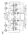
- Fig.1 is a fluid circuit diagram of a brake apparatus
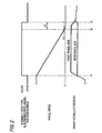
- Fig.2 is a timing chart.
- a master cylinder M of a tandem type includes a first and a second output port 1A and 1B for producing brake fluid pressure according to depressing force applied to a brake pedal P by a vehicle driver.
- Brake pressure controlling unit 4 is provided between a left front wheel brake 2A, a right rear wheel brake 2B, a right front wheel brake 2C and a left rear wheel brake 2D and a first and a second output fluid paths 3A and 3B individually connected to the first and second output ports 1A and 1B.
- the brake pressure controlling unit 4 includes a first, a second, a third and a fourth normally-open-type electromagnetic valve 6A through 6D individually in correspondence with the left front wheel brake 2A, the right rear wheel brake 2B, the right front wheel brake 2C and the left rear wheel brake 2D; a first, a second, a third and a fourth check valve 7A through 7D connected respectively in parallel with the normally-open-type electromagnetic valves 6A through 6D; a first, a second, a third and a fourth normally-close-type electromagnetic valve 8A through 8D individually in correspondence with the respective wheel brakes 2A through 2D; a first and a second reservoir 9A and 9B respectively in correspondence individually with the first and the second output fluid paths 3A and 3B; a first and a second pump 10A and 10B of a plunger type having suction valves 11A and 11B connected to the first and the second reservoirs 9A and 9B and having discharge valves 13A and 13B; a single piece of common electric motor 12 for driving the two pumps
- the first normally-open-type electromagnetic valve 6A is provided between the first output fluid path 3A and the left front brake 2A
- the second normally-open-type electromagnetic valve 6B is provided between the first output fluid path 3A and the right rear wheel brake 2B
- the third normally-open-type electromagnetic valve 6C is provided between the second output fluid path 3B and the right front wheel brake 2C
- the fourth normally-open-type electromagnetic valve 6D is provided between the second output fluid path 3B and the left rear wheel brake 2D.
- first through the fourth check valves 7A through 7D are connected in parallel with the respective normally-open-type electromagnetic valves 6A through 6D such that a flow of a brake fluid from the corresponding wheel brakes 2A through 2D to the master cylinder M is permitted.
- the first normally-close-type electromagnetic valve 8A is provided between the left front wheel brake 2A and the first reservoir 9A
- the second normally-close-typeelectromagneticvalve8B isprovided between the right rear wheel brake 2B and the first reservoir 9A
- the third normally-close-type electromagnetic valve 8C is provided between the right front wheel brake 2C and the second reservoir 9B
- the fourth normally-close-type electromagnetic valve 8D is provided between the left rear wheel brake 2D and the second reservoir 9B.
- the brake pressure controlling unit 4 communicates the master cylinder M and the wheel brakes 2A through 2D and blocks the wheel brakes 2A through 2D from the reservoirs 9A and 9B. That is, the respective normally-open-type electromagnetic valves 6A through 6D are demagnetized and in an opened state, and the respective normally-close-type electromagnetic valves 8A through 8D are a demagnetized and in a closed state.
- the brake fluid pressure outputted from the first output port 1A of the master cylinder M operates to the left front wheel brake 2A via the first normally-open-type electromagnetic valve 6A and operates to the right rear wheel brake 2B via the second normally-open-type electromagnetic valve 6B.
- the brake fluid pressure outputted from the second output port 1B of the master cylinder M operates to the right front wheel brake 2C via the third normally-open-type electromagnetic valve 6C and operates to the left rear wheel brake 2D via the fourth normally-open-type electromagnetic valve 6D.
- the brake pressure controlling unit 4 closes between the master cylinder M and the wheel brakes 2A through 2D, and simultaneously communicates through the wheel brakes 2A through 2D and the reservoirs 9A and 9B at a portion thereof in correspondence with the wheel which is going to be brought into the locked state. That is, the normally-open-type electromagnetic valve in the first through the fourth normally-open-type electromagnetic valves 6A through 6D in correspondence with the wheel which is going to be brought into the locked state is excited and in the closed state, and the normally-close-type electromagnetic valve of the first through the fourth normally-close-type electromagnetic valve 8A through 8D in correspondence with the wheel is excited and in the opened state. Thereby, a part of the brake fluid pressure of the wheel which is going to be brought into the locked state is absorbed by the first reservoir 9A or the second reservoir 9B and the brake fluid pressure of the wheel which is going to be brought into the locked state is reduced.
- the brake pressure controlling unit 4 makes in a state that the wheel brakes 2A through 2D are blocked from the master cylinder M and the reservoirs 9A and 9B. That is, the normally-open-type electromagnetic valves 6A through 6D are excited and in the closed state and the normally-close-type electromagnetic valves 8A through 8D are demagnetized and in the closed state. Further, when the brake fluid pressure is increased, the normally-open-type electromagnetic valves 6A through 6D may be demagnetized and in the opened state, and the normally-close-type electromagnetic valves 8A through 8D may be demagnetized and in the closed state.
- a brake force distribution control for distributing front and rear brake forces by closing the second and the fourth normally-open-type electromagnetic valves 6B and 6D of the first through the fourth normally-open-type electromagnetic valves 6A through 6D of the brake pressure controlling unit 4 in correspondence with the left and the right rear wheels.
- the control unit 16 executes the brake force distribution control by opening the second and the fourth normally-open-type electromagnetic valves 6B and 6D when the brake force distribution control for distributing the front and the rear brake forces is finished by controlling the second and the fourth normally-open-type electromagnetic valves 6B and 6D to the valve closing side.
- control unit 16 receives detected values of wheel speed sensors 17A and 17B for respectively detecting wheel speeds of the left front wheel and the right rear wheel and wheel speed sensors 17C and 17D for respectively detecting wheel speeds of the right front wheel and the left rear wheel and the control unit 16 finishes the brake force distribution control when a predetermined time has elapsed after, for example, the wheel speeds of the right and the left rear wheels detected by the wheel speed sensors 17B and 17D are reduced to be equal to or smaller than a predetermined speed just before the vehicle stops.
- the second and fourth normally-open-type electromagnetic valves 6B and 6D are opened at the time t3 and in accordance therewith, the brake fluid pressure on the rear wheel side increases to be equal to the brake fluid pressure on the front wheel side.
- the brake force distribution control is finished when, for example, the predetermined time ⁇ T elapses just before the vehicle stops after the wheel speed of the rear wheel is reduced to be equal to or smaller than the predetermined speed V0. Therefore, even when the second and the fourth normally-open-type electromagnetic valves 6B and 6D in correspondence with the rear wheels are opened in accordance with finishing the brake force distribution control, it is difficult to recognize a bringing in of the brake pedal P by swing back of the vehicle at a stopping of the vehicle and the strange operational feeling can firmly be prevented from being deteriorated in finishing the brake force distribution control.
- the second and the fourth normally-open-rype electromagnetic valves 6B and 6D corresponding to the wheels maybe closed responding to a starting the brake force distribution control and the brake force distribution control may be finished, for example at time t3' at which an estimated vehicle deceleration becomes a predetermined deceleration DVO after, the wheel speed of the rear wheel is reduced to be equal to or smaller than the predetermined speed V0, for example 2km/h, just before the vehicle stops.
Description
- The present invention relates to a brake control apparatus.
- The present invention relates to a brake control apparatus comprising a brake pressure controlling unit including normally-open-type electromagnetic valves for preventing a fluid pressure from being transmitted from a master cylinder to wheel brakes when the valves close, and a control unit executing an anti-lock brake control resolving a lock tendency of the wheels by controlling the operation of the brake pressure controlling unit according to a result of judgment of the lock tendency of wheels and simultaneously executing a brake force distribution control distributing front and rear brake forces by controlling the normally-open-type electromagnetic valves in correspondence with rear wheels to close in such a manner that the normally-open-type electromagnetic valves are opened when the brake force distribution control is finished. The control unit finishes the brake force distribution control after a vehicle stops and a load applied ahead of the vehicle is released.
- There has already been known a brake control apparatus for carrying out front and rear brake force distribution by controlling a normally-open-type electromagnetic valve provided between a master cylinder and a wheel brake of a rear wheel to a closing side (refer to, for example, Published Japanese Patent Application JP-A-7-144627) .
- Meanwhile, when the brake force distribution control is finished, the normally-open-type electromagnetic valve between the master cylinder and the wheel brake of the rear wheel is opened such that the brake fluid pressure of the rear wheel becomes a value in correspondence with output fluid pressure of the master cylinder. However, because of the opening of the normally-open-type electromagnetic valve, the brake pedal is brought in, and a vehicle driver may experience a strange feeling. Hence, according to the prior art, the brake force distribution control is finished when an estimated vehicle speed becomes equal to or smaller than a predetermined speed just before the vehicle stops, to alleviate the strange feeling of the vehicle driver by bringing in the brake pedal when a swing back of the vehicle body is caused. However, the brake pedal is brought in before causing the swing back of the vehicle is caused before the vehicle stops, and it is difficult to regard that the strange feeling of the vehicle driver can firmly be resolved. The swing back is caused when a load applied ahead of the vehicle is released after the vehicle stops.
- US-A-5,632,535 describes an apparatus according to the preamble of claim 1.
- The present invention has been made in view of such a situation, and it is an object thereof to provide a brake control apparatus firmly preventing the strange operational feeling when the brake force distribution control is finished.
- In order to achieve the above-described object, the present invention provides an apparatus as recited in claim 1.
- The control unit finishes the brake force distribution control after an estimated deceleration is reduced to be equal to or smaller than a predetermined deceleration from when a wheel speed is reduced to be equal to or smaller than a predetermined speed just before the vehicle stops. It is difficult to recognize the bringing in of a brake pedal by swing back of the vehicle when the vehicle stops and the strange operational feeling can firmly be prevented from being deteriorated when the brake force distribution control is finished.
- The predetermined wheel speed may be 2km/h.
- Preferably, the brake pressure control unit further includes a normally-open-type electromagnetic valve in correspondence with a wheel brake, a check valve connected in parallel with the normally-open-type electromagnetic valve, a normally-close-type electromagnetic valve in correspondence with the wheel brake and a reservoir in correspondence with an output fluid path.
-
- Fig. 1 is a fluid circuit diagram of a brake apparatus according to an example of a brake control apparatus;
- Fig.2 is a timing chart; and
- Fig.3 is a timing chart in correspondence to Fig.2 of a brake control apparatus of the present invention.
- Fig.1 and Fig.2 show an example of a brake control apparatus, Fig.1 is a fluid circuit diagram of a brake apparatus and Fig.2 is a timing chart.
- First, in Fig.1, a master cylinder M of a tandem type includes a first and a
second output port front wheel brake 2A, a rightrear wheel brake 2B, a rightfront wheel brake 2C and a leftrear wheel brake 2D and a first and a secondoutput fluid paths second output ports - The brake pressure controlling unit 4 includes a first, a second, a third and a fourth normally-open-type
electromagnetic valve 6A through 6D individually in correspondence with the leftfront wheel brake 2A, the rightrear wheel brake 2B, the rightfront wheel brake 2C and the leftrear wheel brake 2D; a first, a second, a third and afourth check valve 7A through 7D connected respectively in parallel with the normally-open-typeelectromagnetic valves 6A through 6D; a first, a second, a third and a fourth normally-close-typeelectromagnetic valve 8A through 8D individually in correspondence with therespective wheel brakes 2A through 2D; a first and asecond reservoir output fluid paths second pump suction valves 11A and 11B connected to the first and thesecond reservoirs discharge valves electric motor 12 for driving the twopumps orifices pumps output fluid paths control unit 16 for controlling operation of the respective normally-open-typeelectromagnetic valves 6A through 6D, the respective normally-close-typeelectromagnetic valves 8A through 8D and theelectric motor 12. - The first normally-open-type
electromagnetic valve 6A is provided between the firstoutput fluid path 3A and theleft front brake 2A, the second normally-open-typeelectromagnetic valve 6B is provided between the firstoutput fluid path 3A and the rightrear wheel brake 2B, the third normally-open-typeelectromagnetic valve 6C is provided between the secondoutput fluid path 3B and the rightfront wheel brake 2C and the fourth normally-open-typeelectromagnetic valve 6D is provided between the secondoutput fluid path 3B and the leftrear wheel brake 2D. - Further, the first through the
fourth check valves 7A through 7D are connected in parallel with the respective normally-open-typeelectromagnetic valves 6A through 6D such that a flow of a brake fluid from thecorresponding wheel brakes 2A through 2D to the master cylinder M is permitted. - The first normally-close-type
electromagnetic valve 8A is provided between the leftfront wheel brake 2A and thefirst reservoir 9A, the second normally-close-typeelectromagneticvalve8Bisprovided between the rightrear wheel brake 2B and thefirst reservoir 9A, the third normally-close-type electromagnetic valve 8C is provided between the rightfront wheel brake 2C and thesecond reservoir 9B and the fourth normally-close-typeelectromagnetic valve 8D is provided between the leftrear wheel brake 2D and thesecond reservoir 9B. - In normally braking operation when there is not a possibility of locking the respective wheels, the brake pressure controlling unit 4 communicates the master cylinder M and the
wheel brakes 2A through 2D and blocks thewheel brakes 2A through 2D from thereservoirs electromagnetic valves 6A through 6D are demagnetized and in an opened state, and the respective normally-close-typeelectromagnetic valves 8A through 8D are a demagnetized and in a closed state. The brake fluid pressure outputted from thefirst output port 1A of the master cylinder M operates to the leftfront wheel brake 2A via the first normally-open-typeelectromagnetic valve 6A and operates to the rightrear wheel brake 2B via the second normally-open-typeelectromagnetic valve 6B. Further, the brake fluid pressure outputted from thesecond output port 1B of the master cylinder M operates to the rightfront wheel brake 2C via the third normally-open-typeelectromagnetic valve 6C and operates to the leftrear wheel brake 2D via the fourth normally-open-typeelectromagnetic valve 6D. - When the wheel is going to be brought into a locked state in the braking operation, the brake pressure controlling unit 4 closes between the master cylinder M and the
wheel brakes 2A through 2D, and simultaneously communicates through thewheel brakes 2A through 2D and thereservoirs electromagnetic valves 6A through 6D in correspondence with the wheel which is going to be brought into the locked state is excited and in the closed state, and the normally-close-type electromagnetic valve of the first through the fourth normally-close-typeelectromagnetic valve 8A through 8D in correspondence with the wheel is excited and in the opened state. Thereby, a part of the brake fluid pressure of the wheel which is going to be brought into the locked state is absorbed by thefirst reservoir 9A or thesecond reservoir 9B and the brake fluid pressure of the wheel which is going to be brought into the locked state is reduced. - Further, when the brake fluid pressure maintains constant pressure, the brake pressure controlling unit 4 makes in a state that the
wheel brakes 2A through 2D are blocked from the master cylinder M and thereservoirs electromagnetic valves 6A through 6D are excited and in the closed state and the normally-close-typeelectromagnetic valves 8A through 8D are demagnetized and in the closed state. Further, when the brake fluid pressure is increased, the normally-open-typeelectromagnetic valves 6A through 6D may be demagnetized and in the opened state, and the normally-close-typeelectromagnetic valves 8A through 8D may be demagnetized and in the closed state. - By controlling to demagnetize and excite the respective normally-open-type
electromagnetic valves 6A through 6D and the respective normally-close-typeelectromagnetic valves 8A through 8D by thecontrol unit 16 in this way, the wheel can be controlled efficiently without been locked. - Further, in braking operation, there can also be carried out a brake force distribution control for distributing front and rear brake forces by closing the second and the fourth normally-open-type
electromagnetic valves electromagnetic valves 6A through 6D of the brake pressure controlling unit 4 in correspondence with the left and the right rear wheels. Thecontrol unit 16 executes the brake force distribution control by opening the second and the fourth normally-open-typeelectromagnetic valves electromagnetic valves - Further, the
control unit 16 receives detected values ofwheel speed sensors wheel speed sensors control unit 16 finishes the brake force distribution control when a predetermined time has elapsed after, for example, the wheel speeds of the right and the left rear wheels detected by thewheel speed sensors - That is, in Fig.2, in the brake force distribution control at the time of braking of the vehicle, in accordance with starting the brake force distribution control at time t1 in a braked state, the second and the fourth normally-open-type
electromagnetic valves electromagnetic valves - Next, explaining the operation of the example which is not in accordance with the invention, the brake force distribution control is finished when, for example, the predetermined time ΔT elapses just before the vehicle stops after the wheel speed of the rear wheel is reduced to be equal to or smaller than the predetermined speed V0. Therefore, even when the second and the fourth normally-open-type
electromagnetic valves - In contrast thereto, when the brake force distribution control is finished when the vehicle speed becomes equal to or smaller than the predetermined speed V0, as shown by a broken line of Fig.2, the brake fluid pressure on the rear wheel side is increased before the stopping of the vehicle, and the operational feeling may be deteriorated by bringing in of the brake pedal P.
- According to the present invention, as shown in Fig.3, at time t1' in the braked state, the second and the fourth normally-open-rype
electromagnetic valves - Also according to the invention, it is difficult to recognize the bringing in of the brake pedal P by swing back of the vehicle at the stopping of the vehicle and the operational feeling can firmly be prevented from being deteriorated in finishing the brake force distribution control.
- While there has been described a preferred embodiment of the present invention, it will be obvious to those skilled in the art that various changes and modifications may be made therein without departing from the present invention as defined in the appended claims.
- As described above, according to the present invention, it is difficult to recognize the bringing in of the brake pedal by swing back of the vehicle at the stopping of the vehicle, and the operational feeling can firmly be prevented from being deteriorated in finishing the brake force distribution control.
Claims (3)
- A brake control apparatus comprising:a brake pressure controlling unit (4) including normally-open-type electromagnetic valves (6A to 6D) for preventing a fluid pressure transmitted from a master cylinder (M) to wheel brakes (2A to 2D) when the valves (6A to 6D) close, anda control unit (16) executing an anti-lock brake control resolving a lock tendency of the wheels by controlling the operation of the brake pressure controlling unit (4) according to a result of judgment of the lock tendency of wheels, and simultaneously executing a brake force distribution control distributing front and rear brake forces by controlling the normally-open-type electromagnetic valves (6A to 6D) in correspondence with rear wheels to close in such a manner that the normally-open-type electromagnetic valves (6A to 6D) are opened when the brake force distribution control is finished;wherein the control unit (16) finishes the brake force distribution control only when a frontward force is not any longer applied to the vehicle;
characterized in that
the control unit (16) finishes the brake force distribution control after an estimated deceleration is reduced to be equal to a smaller than a predetermined deceleration after the wheel speed of the vehicle is reduced to be equal to or smaller than a predetermined wheel speed just before the vehicle stops. - A brake control apparatus as set forth in claim 1, wherein the predetermined wheel speed is 2 km/h.
- A brake control apparatus as set forth in claim 1 or 2, the brake pressure control unit (16) further including:a normally-open-type electromagnetic valve (6A to 6D) in correspondence with a wheel brake (2A to 2D);a check valve (7A to 7D) connected in parallel with the normally-open-type electromagnetic valve (6A to 6D);a normally-closed-type electromagnetic valve (8A to 8D) in correspondence with the wheel brake (2A to 2D); anda reservoir in correspondence with an output fluid path (3A, 3B).
Applications Claiming Priority (2)
| Application Number | Priority Date | Filing Date | Title |
|---|---|---|---|
| JP2003009368A JP2004217155A (en) | 2003-01-17 | 2003-01-17 | Brake controller for vehicle |
| JP2003009368 | 2003-01-17 |
Publications (3)
| Publication Number | Publication Date |
|---|---|
| EP1439104A1 EP1439104A1 (en) | 2004-07-21 |
| EP1439104A8 EP1439104A8 (en) | 2004-10-20 |
| EP1439104B1 true EP1439104B1 (en) | 2007-03-07 |
Family
ID=32588559
Family Applications (1)
| Application Number | Title | Priority Date | Filing Date |
|---|---|---|---|
| EP04000913A Expired - Lifetime EP1439104B1 (en) | 2003-01-17 | 2004-01-16 | Brake control apparatus |
Country Status (4)
| Country | Link |
|---|---|
| US (1) | US7156472B2 (en) |
| EP (1) | EP1439104B1 (en) |
| JP (1) | JP2004217155A (en) |
| DE (1) | DE602004005081T2 (en) |
Families Citing this family (5)
| Publication number | Priority date | Publication date | Assignee | Title |
|---|---|---|---|---|
| JP4802706B2 (en) * | 2005-02-17 | 2011-10-26 | トヨタ自動車株式会社 | Electronically controlled hydraulic brake system |
| WO2010035115A1 (en) * | 2008-09-26 | 2010-04-01 | Toyota Jidosha Kabushiki Kaisha | Automatic vehicle braking system and method |
| JP6147963B2 (en) * | 2012-04-13 | 2017-06-14 | 日本信号株式会社 | Train brake system |
| WO2020180142A1 (en) | 2019-03-06 | 2020-09-10 | Mando Corporation | Brake system |
| JP7392355B2 (en) | 2019-09-27 | 2023-12-06 | 株式会社アドヴィックス | Vehicle braking control device |
Family Cites Families (7)
| Publication number | Priority date | Publication date | Assignee | Title |
|---|---|---|---|---|
| JP3141655B2 (en) | 1993-11-24 | 2001-03-05 | トヨタ自動車株式会社 | Brake fluid pressure control device |
| US5632535A (en) | 1995-08-28 | 1997-05-27 | Kelsey-Hayes Company | Dynamic rear proportioning brake system |
| JPH1170874A (en) | 1996-08-09 | 1999-03-16 | Denso Corp | Vehicle brake device |
| JP3473659B2 (en) * | 1996-09-09 | 2003-12-08 | トヨタ自動車株式会社 | Braking force distribution control device |
| JPH11180281A (en) | 1997-12-19 | 1999-07-06 | Nisshinbo Ind Inc | Distribution of braking force control method |
| JP2000095087A (en) * | 1998-09-22 | 2000-04-04 | Nisshinbo Ind Inc | Braking force distribution control device |
| DE10131323A1 (en) | 2000-07-26 | 2002-05-02 | Continental Teves Ag & Co Ohg | Compensating or preventing jolts when braking a vehicle to rest involves activating special regulation procedure during braking on reaching or falling below threshold vehicle speed value |
-
2003
- 2003-01-17 JP JP2003009368A patent/JP2004217155A/en active Pending
-
2004
- 2004-01-14 US US10/756,392 patent/US7156472B2/en not_active Expired - Lifetime
- 2004-01-16 EP EP04000913A patent/EP1439104B1/en not_active Expired - Lifetime
- 2004-01-16 DE DE602004005081T patent/DE602004005081T2/en not_active Expired - Lifetime
Also Published As
| Publication number | Publication date |
|---|---|
| DE602004005081T2 (en) | 2007-11-22 |
| DE602004005081D1 (en) | 2007-04-19 |
| US20040140712A1 (en) | 2004-07-22 |
| EP1439104A1 (en) | 2004-07-21 |
| JP2004217155A (en) | 2004-08-05 |
| US7156472B2 (en) | 2007-01-02 |
| EP1439104A8 (en) | 2004-10-20 |
Similar Documents
| Publication | Publication Date | Title |
|---|---|---|
| US6007163A (en) | Brake control apparatus for a vehicle | |
| JP4561464B2 (en) | Brake hydraulic pressure control device for vehicles | |
| US6349995B1 (en) | Brake control system for a vehicle | |
| JPH0611269Y2 (en) | Hydraulic brake device | |
| JP4211071B2 (en) | Brake control device for vehicle | |
| JP5461513B2 (en) | Brake hydraulic pressure control device for vehicles | |
| EP1439104B1 (en) | Brake control apparatus | |
| JP3726455B2 (en) | Brake control device for vehicle | |
| JP4389294B2 (en) | Brake control device for vehicle | |
| US5700069A (en) | Anti-skid control system for an automotive vehicle | |
| JP2581065B2 (en) | Hydraulic brake device | |
| US5924777A (en) | Antilock brake system | |
| US6422660B2 (en) | Brake control system for a vehicle | |
| JP4030456B2 (en) | Brake device for vehicle | |
| JP4224528B2 (en) | Brake control device for vehicle | |
| JP4432237B2 (en) | Brake control device for vehicle | |
| JP2756507B2 (en) | Vehicle traction control method | |
| JP2001138887A (en) | Braking device for vehicle | |
| JP3913992B2 (en) | Anti-lock brake control method for motorcycles | |
| US5613742A (en) | Asynchronous rear dump logic in ABS control systems | |
| JP4243011B2 (en) | Anti-lock brake control method for motorcycles | |
| JP4364444B2 (en) | Method for judging friction coefficient of road surface for motorcycle | |
| JPH08175368A (en) | Antiskid control device | |
| JP3726457B2 (en) | Brake control device for vehicle | |
| JP3887307B2 (en) | Electric motor drive device |
Legal Events
| Date | Code | Title | Description |
|---|---|---|---|
| PUAI | Public reference made under article 153(3) epc to a published international application that has entered the european phase |
Free format text: ORIGINAL CODE: 0009012 |
|
| AK | Designated contracting states |
Kind code of ref document: A1 Designated state(s): AT BE BG CH CY CZ DE DK EE ES FI FR GB GR HU IE IT LI LU MC NL PT RO SE SI SK TR |
|
| AX | Request for extension of the european patent |
Extension state: AL LT LV MK |
|
| RIN1 | Information on inventor provided before grant (corrected) |
Inventor name: MATSUMOTO, HIROAKIC/O NISSIN KOGYO CO., LTD. |
|
| RIN1 | Information on inventor provided before grant (corrected) |
Inventor name: MATSUMOTO, HIROAKIC/O NISSIN KOGYO CO., LTD. |
|
| 17P | Request for examination filed |
Effective date: 20041209 |
|
| AKX | Designation fees paid |
Designated state(s): DE GB |
|
| 17Q | First examination report despatched |
Effective date: 20050502 |
|
| GRAP | Despatch of communication of intention to grant a patent |
Free format text: ORIGINAL CODE: EPIDOSNIGR1 |
|
| GRAS | Grant fee paid |
Free format text: ORIGINAL CODE: EPIDOSNIGR3 |
|
| GRAA | (expected) grant |
Free format text: ORIGINAL CODE: 0009210 |
|
| AK | Designated contracting states |
Kind code of ref document: B1 Designated state(s): DE GB |
|
| REG | Reference to a national code |
Ref country code: GB Ref legal event code: FG4D |
|
| REF | Corresponds to: |
Ref document number: 602004005081 Country of ref document: DE Date of ref document: 20070419 Kind code of ref document: P |
|
| PLBE | No opposition filed within time limit |
Free format text: ORIGINAL CODE: 0009261 |
|
| STAA | Information on the status of an ep patent application or granted ep patent |
Free format text: STATUS: NO OPPOSITION FILED WITHIN TIME LIMIT |
|
| 26N | No opposition filed |
Effective date: 20071210 |
|
| REG | Reference to a national code |
Ref country code: DE Ref legal event code: R082 Ref document number: 602004005081 Country of ref document: DE Representative=s name: HOFFMANN - EITLE PATENT- UND RECHTSANWAELTE PA, DE Ref country code: DE Ref legal event code: R081 Ref document number: 602004005081 Country of ref document: DE Owner name: AUTOLIV NISSIN BRAKE SYSTEMS JAPAN CO., LTD., , JP Free format text: FORMER OWNER: NISSIN KOGYO CO., LTD., UEDA, NAGANO, JP |
|
| REG | Reference to a national code |
Ref country code: GB Ref legal event code: 732E Free format text: REGISTERED BETWEEN 20160811 AND 20160817 |
|
| PGFP | Annual fee paid to national office [announced via postgrant information from national office to epo] |
Ref country code: GB Payment date: 20230124 Year of fee payment: 20 Ref country code: DE Payment date: 20230119 Year of fee payment: 20 |
|
| REG | Reference to a national code |
Ref country code: DE Ref legal event code: R071 Ref document number: 602004005081 Country of ref document: DE |
|
| REG | Reference to a national code |
Ref country code: GB Ref legal event code: PE20 Expiry date: 20240115 |