EP1439086A2 - Driving apparatus for an electric vehicle - Google Patents
Driving apparatus for an electric vehicle Download PDFInfo
- Publication number
- EP1439086A2 EP1439086A2 EP04250193A EP04250193A EP1439086A2 EP 1439086 A2 EP1439086 A2 EP 1439086A2 EP 04250193 A EP04250193 A EP 04250193A EP 04250193 A EP04250193 A EP 04250193A EP 1439086 A2 EP1439086 A2 EP 1439086A2
- Authority
- EP
- European Patent Office
- Prior art keywords
- engine
- power
- motor
- axle
- side input
- Prior art date
- Legal status (The legal status is an assumption and is not a legal conclusion. Google has not performed a legal analysis and makes no representation as to the accuracy of the status listed.)
- Withdrawn
Links
Images


Classifications
-
- B—PERFORMING OPERATIONS; TRANSPORTING
- B60—VEHICLES IN GENERAL
- B60K—ARRANGEMENT OR MOUNTING OF PROPULSION UNITS OR OF TRANSMISSIONS IN VEHICLES; ARRANGEMENT OR MOUNTING OF PLURAL DIVERSE PRIME-MOVERS IN VEHICLES; AUXILIARY DRIVES FOR VEHICLES; INSTRUMENTATION OR DASHBOARDS FOR VEHICLES; ARRANGEMENTS IN CONNECTION WITH COOLING, AIR INTAKE, GAS EXHAUST OR FUEL SUPPLY OF PROPULSION UNITS IN VEHICLES
- B60K6/00—Arrangement or mounting of plural diverse prime-movers for mutual or common propulsion, e.g. hybrid propulsion systems comprising electric motors and internal combustion engines
- B60K6/20—Arrangement or mounting of plural diverse prime-movers for mutual or common propulsion, e.g. hybrid propulsion systems comprising electric motors and internal combustion engines the prime-movers consisting of electric motors and internal combustion engines, e.g. HEVs
- B60K6/22—Arrangement or mounting of plural diverse prime-movers for mutual or common propulsion, e.g. hybrid propulsion systems comprising electric motors and internal combustion engines the prime-movers consisting of electric motors and internal combustion engines, e.g. HEVs characterised by apparatus, components or means specially adapted for HEVs
- B60K6/24—Arrangement or mounting of plural diverse prime-movers for mutual or common propulsion, e.g. hybrid propulsion systems comprising electric motors and internal combustion engines the prime-movers consisting of electric motors and internal combustion engines, e.g. HEVs characterised by apparatus, components or means specially adapted for HEVs characterised by the combustion engines
-
- B—PERFORMING OPERATIONS; TRANSPORTING
- B60—VEHICLES IN GENERAL
- B60W—CONJOINT CONTROL OF VEHICLE SUB-UNITS OF DIFFERENT TYPE OR DIFFERENT FUNCTION; CONTROL SYSTEMS SPECIALLY ADAPTED FOR HYBRID VEHICLES; ROAD VEHICLE DRIVE CONTROL SYSTEMS FOR PURPOSES NOT RELATED TO THE CONTROL OF A PARTICULAR SUB-UNIT
- B60W20/00—Control systems specially adapted for hybrid vehicles
- B60W20/40—Controlling the engagement or disengagement of prime movers, e.g. for transition between prime movers
-
- B—PERFORMING OPERATIONS; TRANSPORTING
- B60—VEHICLES IN GENERAL
- B60K—ARRANGEMENT OR MOUNTING OF PROPULSION UNITS OR OF TRANSMISSIONS IN VEHICLES; ARRANGEMENT OR MOUNTING OF PLURAL DIVERSE PRIME-MOVERS IN VEHICLES; AUXILIARY DRIVES FOR VEHICLES; INSTRUMENTATION OR DASHBOARDS FOR VEHICLES; ARRANGEMENTS IN CONNECTION WITH COOLING, AIR INTAKE, GAS EXHAUST OR FUEL SUPPLY OF PROPULSION UNITS IN VEHICLES
- B60K6/00—Arrangement or mounting of plural diverse prime-movers for mutual or common propulsion, e.g. hybrid propulsion systems comprising electric motors and internal combustion engines
- B60K6/20—Arrangement or mounting of plural diverse prime-movers for mutual or common propulsion, e.g. hybrid propulsion systems comprising electric motors and internal combustion engines the prime-movers consisting of electric motors and internal combustion engines, e.g. HEVs
- B60K6/22—Arrangement or mounting of plural diverse prime-movers for mutual or common propulsion, e.g. hybrid propulsion systems comprising electric motors and internal combustion engines the prime-movers consisting of electric motors and internal combustion engines, e.g. HEVs characterised by apparatus, components or means specially adapted for HEVs
- B60K6/26—Arrangement or mounting of plural diverse prime-movers for mutual or common propulsion, e.g. hybrid propulsion systems comprising electric motors and internal combustion engines the prime-movers consisting of electric motors and internal combustion engines, e.g. HEVs characterised by apparatus, components or means specially adapted for HEVs characterised by the motors or the generators
-
- B—PERFORMING OPERATIONS; TRANSPORTING
- B60—VEHICLES IN GENERAL
- B60K—ARRANGEMENT OR MOUNTING OF PROPULSION UNITS OR OF TRANSMISSIONS IN VEHICLES; ARRANGEMENT OR MOUNTING OF PLURAL DIVERSE PRIME-MOVERS IN VEHICLES; AUXILIARY DRIVES FOR VEHICLES; INSTRUMENTATION OR DASHBOARDS FOR VEHICLES; ARRANGEMENTS IN CONNECTION WITH COOLING, AIR INTAKE, GAS EXHAUST OR FUEL SUPPLY OF PROPULSION UNITS IN VEHICLES
- B60K6/00—Arrangement or mounting of plural diverse prime-movers for mutual or common propulsion, e.g. hybrid propulsion systems comprising electric motors and internal combustion engines
- B60K6/20—Arrangement or mounting of plural diverse prime-movers for mutual or common propulsion, e.g. hybrid propulsion systems comprising electric motors and internal combustion engines the prime-movers consisting of electric motors and internal combustion engines, e.g. HEVs
- B60K6/22—Arrangement or mounting of plural diverse prime-movers for mutual or common propulsion, e.g. hybrid propulsion systems comprising electric motors and internal combustion engines the prime-movers consisting of electric motors and internal combustion engines, e.g. HEVs characterised by apparatus, components or means specially adapted for HEVs
- B60K6/36—Arrangement or mounting of plural diverse prime-movers for mutual or common propulsion, e.g. hybrid propulsion systems comprising electric motors and internal combustion engines the prime-movers consisting of electric motors and internal combustion engines, e.g. HEVs characterised by apparatus, components or means specially adapted for HEVs characterised by the transmission gearings
-
- B—PERFORMING OPERATIONS; TRANSPORTING
- B60—VEHICLES IN GENERAL
- B60K—ARRANGEMENT OR MOUNTING OF PROPULSION UNITS OR OF TRANSMISSIONS IN VEHICLES; ARRANGEMENT OR MOUNTING OF PLURAL DIVERSE PRIME-MOVERS IN VEHICLES; AUXILIARY DRIVES FOR VEHICLES; INSTRUMENTATION OR DASHBOARDS FOR VEHICLES; ARRANGEMENTS IN CONNECTION WITH COOLING, AIR INTAKE, GAS EXHAUST OR FUEL SUPPLY OF PROPULSION UNITS IN VEHICLES
- B60K6/00—Arrangement or mounting of plural diverse prime-movers for mutual or common propulsion, e.g. hybrid propulsion systems comprising electric motors and internal combustion engines
- B60K6/20—Arrangement or mounting of plural diverse prime-movers for mutual or common propulsion, e.g. hybrid propulsion systems comprising electric motors and internal combustion engines the prime-movers consisting of electric motors and internal combustion engines, e.g. HEVs
- B60K6/22—Arrangement or mounting of plural diverse prime-movers for mutual or common propulsion, e.g. hybrid propulsion systems comprising electric motors and internal combustion engines the prime-movers consisting of electric motors and internal combustion engines, e.g. HEVs characterised by apparatus, components or means specially adapted for HEVs
- B60K6/38—Arrangement or mounting of plural diverse prime-movers for mutual or common propulsion, e.g. hybrid propulsion systems comprising electric motors and internal combustion engines the prime-movers consisting of electric motors and internal combustion engines, e.g. HEVs characterised by apparatus, components or means specially adapted for HEVs characterised by the driveline clutches
- B60K6/383—One-way clutches or freewheel devices
-
- B—PERFORMING OPERATIONS; TRANSPORTING
- B60—VEHICLES IN GENERAL
- B60K—ARRANGEMENT OR MOUNTING OF PROPULSION UNITS OR OF TRANSMISSIONS IN VEHICLES; ARRANGEMENT OR MOUNTING OF PLURAL DIVERSE PRIME-MOVERS IN VEHICLES; AUXILIARY DRIVES FOR VEHICLES; INSTRUMENTATION OR DASHBOARDS FOR VEHICLES; ARRANGEMENTS IN CONNECTION WITH COOLING, AIR INTAKE, GAS EXHAUST OR FUEL SUPPLY OF PROPULSION UNITS IN VEHICLES
- B60K6/00—Arrangement or mounting of plural diverse prime-movers for mutual or common propulsion, e.g. hybrid propulsion systems comprising electric motors and internal combustion engines
- B60K6/20—Arrangement or mounting of plural diverse prime-movers for mutual or common propulsion, e.g. hybrid propulsion systems comprising electric motors and internal combustion engines the prime-movers consisting of electric motors and internal combustion engines, e.g. HEVs
- B60K6/22—Arrangement or mounting of plural diverse prime-movers for mutual or common propulsion, e.g. hybrid propulsion systems comprising electric motors and internal combustion engines the prime-movers consisting of electric motors and internal combustion engines, e.g. HEVs characterised by apparatus, components or means specially adapted for HEVs
- B60K6/38—Arrangement or mounting of plural diverse prime-movers for mutual or common propulsion, e.g. hybrid propulsion systems comprising electric motors and internal combustion engines the prime-movers consisting of electric motors and internal combustion engines, e.g. HEVs characterised by apparatus, components or means specially adapted for HEVs characterised by the driveline clutches
- B60K6/387—Actuated clutches, i.e. clutches engaged or disengaged by electric, hydraulic or mechanical actuating means
-
- B—PERFORMING OPERATIONS; TRANSPORTING
- B60—VEHICLES IN GENERAL
- B60K—ARRANGEMENT OR MOUNTING OF PROPULSION UNITS OR OF TRANSMISSIONS IN VEHICLES; ARRANGEMENT OR MOUNTING OF PLURAL DIVERSE PRIME-MOVERS IN VEHICLES; AUXILIARY DRIVES FOR VEHICLES; INSTRUMENTATION OR DASHBOARDS FOR VEHICLES; ARRANGEMENTS IN CONNECTION WITH COOLING, AIR INTAKE, GAS EXHAUST OR FUEL SUPPLY OF PROPULSION UNITS IN VEHICLES
- B60K6/00—Arrangement or mounting of plural diverse prime-movers for mutual or common propulsion, e.g. hybrid propulsion systems comprising electric motors and internal combustion engines
- B60K6/20—Arrangement or mounting of plural diverse prime-movers for mutual or common propulsion, e.g. hybrid propulsion systems comprising electric motors and internal combustion engines the prime-movers consisting of electric motors and internal combustion engines, e.g. HEVs
- B60K6/22—Arrangement or mounting of plural diverse prime-movers for mutual or common propulsion, e.g. hybrid propulsion systems comprising electric motors and internal combustion engines the prime-movers consisting of electric motors and internal combustion engines, e.g. HEVs characterised by apparatus, components or means specially adapted for HEVs
- B60K6/40—Arrangement or mounting of plural diverse prime-movers for mutual or common propulsion, e.g. hybrid propulsion systems comprising electric motors and internal combustion engines the prime-movers consisting of electric motors and internal combustion engines, e.g. HEVs characterised by apparatus, components or means specially adapted for HEVs characterised by the assembly or relative disposition of components
-
- B—PERFORMING OPERATIONS; TRANSPORTING
- B60—VEHICLES IN GENERAL
- B60K—ARRANGEMENT OR MOUNTING OF PROPULSION UNITS OR OF TRANSMISSIONS IN VEHICLES; ARRANGEMENT OR MOUNTING OF PLURAL DIVERSE PRIME-MOVERS IN VEHICLES; AUXILIARY DRIVES FOR VEHICLES; INSTRUMENTATION OR DASHBOARDS FOR VEHICLES; ARRANGEMENTS IN CONNECTION WITH COOLING, AIR INTAKE, GAS EXHAUST OR FUEL SUPPLY OF PROPULSION UNITS IN VEHICLES
- B60K6/00—Arrangement or mounting of plural diverse prime-movers for mutual or common propulsion, e.g. hybrid propulsion systems comprising electric motors and internal combustion engines
- B60K6/20—Arrangement or mounting of plural diverse prime-movers for mutual or common propulsion, e.g. hybrid propulsion systems comprising electric motors and internal combustion engines the prime-movers consisting of electric motors and internal combustion engines, e.g. HEVs
- B60K6/42—Arrangement or mounting of plural diverse prime-movers for mutual or common propulsion, e.g. hybrid propulsion systems comprising electric motors and internal combustion engines the prime-movers consisting of electric motors and internal combustion engines, e.g. HEVs characterised by the architecture of the hybrid electric vehicle
- B60K6/44—Series-parallel type
- B60K6/442—Series-parallel switching type
-
- B—PERFORMING OPERATIONS; TRANSPORTING
- B60—VEHICLES IN GENERAL
- B60K—ARRANGEMENT OR MOUNTING OF PROPULSION UNITS OR OF TRANSMISSIONS IN VEHICLES; ARRANGEMENT OR MOUNTING OF PLURAL DIVERSE PRIME-MOVERS IN VEHICLES; AUXILIARY DRIVES FOR VEHICLES; INSTRUMENTATION OR DASHBOARDS FOR VEHICLES; ARRANGEMENTS IN CONNECTION WITH COOLING, AIR INTAKE, GAS EXHAUST OR FUEL SUPPLY OF PROPULSION UNITS IN VEHICLES
- B60K6/00—Arrangement or mounting of plural diverse prime-movers for mutual or common propulsion, e.g. hybrid propulsion systems comprising electric motors and internal combustion engines
- B60K6/20—Arrangement or mounting of plural diverse prime-movers for mutual or common propulsion, e.g. hybrid propulsion systems comprising electric motors and internal combustion engines the prime-movers consisting of electric motors and internal combustion engines, e.g. HEVs
- B60K6/50—Architecture of the driveline characterised by arrangement or kind of transmission units
- B60K6/54—Transmission for changing ratio
- B60K6/543—Transmission for changing ratio the transmission being a continuously variable transmission
-
- B—PERFORMING OPERATIONS; TRANSPORTING
- B60—VEHICLES IN GENERAL
- B60K—ARRANGEMENT OR MOUNTING OF PROPULSION UNITS OR OF TRANSMISSIONS IN VEHICLES; ARRANGEMENT OR MOUNTING OF PLURAL DIVERSE PRIME-MOVERS IN VEHICLES; AUXILIARY DRIVES FOR VEHICLES; INSTRUMENTATION OR DASHBOARDS FOR VEHICLES; ARRANGEMENTS IN CONNECTION WITH COOLING, AIR INTAKE, GAS EXHAUST OR FUEL SUPPLY OF PROPULSION UNITS IN VEHICLES
- B60K6/00—Arrangement or mounting of plural diverse prime-movers for mutual or common propulsion, e.g. hybrid propulsion systems comprising electric motors and internal combustion engines
- B60K6/20—Arrangement or mounting of plural diverse prime-movers for mutual or common propulsion, e.g. hybrid propulsion systems comprising electric motors and internal combustion engines the prime-movers consisting of electric motors and internal combustion engines, e.g. HEVs
- B60K6/50—Architecture of the driveline characterised by arrangement or kind of transmission units
- B60K6/54—Transmission for changing ratio
- B60K6/547—Transmission for changing ratio the transmission being a stepped gearing
-
- B—PERFORMING OPERATIONS; TRANSPORTING
- B60—VEHICLES IN GENERAL
- B60W—CONJOINT CONTROL OF VEHICLE SUB-UNITS OF DIFFERENT TYPE OR DIFFERENT FUNCTION; CONTROL SYSTEMS SPECIALLY ADAPTED FOR HYBRID VEHICLES; ROAD VEHICLE DRIVE CONTROL SYSTEMS FOR PURPOSES NOT RELATED TO THE CONTROL OF A PARTICULAR SUB-UNIT
- B60W10/00—Conjoint control of vehicle sub-units of different type or different function
- B60W10/02—Conjoint control of vehicle sub-units of different type or different function including control of driveline clutches
-
- B—PERFORMING OPERATIONS; TRANSPORTING
- B60—VEHICLES IN GENERAL
- B60W—CONJOINT CONTROL OF VEHICLE SUB-UNITS OF DIFFERENT TYPE OR DIFFERENT FUNCTION; CONTROL SYSTEMS SPECIALLY ADAPTED FOR HYBRID VEHICLES; ROAD VEHICLE DRIVE CONTROL SYSTEMS FOR PURPOSES NOT RELATED TO THE CONTROL OF A PARTICULAR SUB-UNIT
- B60W10/00—Conjoint control of vehicle sub-units of different type or different function
- B60W10/10—Conjoint control of vehicle sub-units of different type or different function including control of change-speed gearings
-
- F—MECHANICAL ENGINEERING; LIGHTING; HEATING; WEAPONS; BLASTING
- F16—ENGINEERING ELEMENTS AND UNITS; GENERAL MEASURES FOR PRODUCING AND MAINTAINING EFFECTIVE FUNCTIONING OF MACHINES OR INSTALLATIONS; THERMAL INSULATION IN GENERAL
- F16H—GEARING
- F16H3/00—Toothed gearings for conveying rotary motion with variable gear ratio or for reversing rotary motion
- F16H3/02—Toothed gearings for conveying rotary motion with variable gear ratio or for reversing rotary motion without gears having orbital motion
- F16H3/08—Toothed gearings for conveying rotary motion with variable gear ratio or for reversing rotary motion without gears having orbital motion exclusively or essentially with continuously meshing gears, that can be disengaged from their shafts
- F16H3/087—Toothed gearings for conveying rotary motion with variable gear ratio or for reversing rotary motion without gears having orbital motion exclusively or essentially with continuously meshing gears, that can be disengaged from their shafts characterised by the disposition of the gears
- F16H3/089—Toothed gearings for conveying rotary motion with variable gear ratio or for reversing rotary motion without gears having orbital motion exclusively or essentially with continuously meshing gears, that can be disengaged from their shafts characterised by the disposition of the gears all of the meshing gears being supported by a pair of parallel shafts, one being the input shaft and the other the output shaft, there being no countershaft involved
-
- F—MECHANICAL ENGINEERING; LIGHTING; HEATING; WEAPONS; BLASTING
- F16—ENGINEERING ELEMENTS AND UNITS; GENERAL MEASURES FOR PRODUCING AND MAINTAINING EFFECTIVE FUNCTIONING OF MACHINES OR INSTALLATIONS; THERMAL INSULATION IN GENERAL
- F16H—GEARING
- F16H3/00—Toothed gearings for conveying rotary motion with variable gear ratio or for reversing rotary motion
- F16H3/02—Toothed gearings for conveying rotary motion with variable gear ratio or for reversing rotary motion without gears having orbital motion
- F16H3/08—Toothed gearings for conveying rotary motion with variable gear ratio or for reversing rotary motion without gears having orbital motion exclusively or essentially with continuously meshing gears, that can be disengaged from their shafts
- F16H3/087—Toothed gearings for conveying rotary motion with variable gear ratio or for reversing rotary motion without gears having orbital motion exclusively or essentially with continuously meshing gears, that can be disengaged from their shafts characterised by the disposition of the gears
- F16H3/091—Toothed gearings for conveying rotary motion with variable gear ratio or for reversing rotary motion without gears having orbital motion exclusively or essentially with continuously meshing gears, that can be disengaged from their shafts characterised by the disposition of the gears including a single countershaft
- F16H3/0915—Toothed gearings for conveying rotary motion with variable gear ratio or for reversing rotary motion without gears having orbital motion exclusively or essentially with continuously meshing gears, that can be disengaged from their shafts characterised by the disposition of the gears including a single countershaft with coaxial input and output shafts
-
- F—MECHANICAL ENGINEERING; LIGHTING; HEATING; WEAPONS; BLASTING
- F16—ENGINEERING ELEMENTS AND UNITS; GENERAL MEASURES FOR PRODUCING AND MAINTAINING EFFECTIVE FUNCTIONING OF MACHINES OR INSTALLATIONS; THERMAL INSULATION IN GENERAL
- F16H—GEARING
- F16H3/00—Toothed gearings for conveying rotary motion with variable gear ratio or for reversing rotary motion
- F16H3/44—Toothed gearings for conveying rotary motion with variable gear ratio or for reversing rotary motion using gears having orbital motion
- F16H3/46—Gearings having only two central gears, connected by orbital gears
- F16H3/48—Gearings having only two central gears, connected by orbital gears with single orbital gears or pairs of rigidly-connected orbital gears
- F16H3/52—Gearings having only two central gears, connected by orbital gears with single orbital gears or pairs of rigidly-connected orbital gears comprising orbital spur gears
- F16H3/54—Gearings having only two central gears, connected by orbital gears with single orbital gears or pairs of rigidly-connected orbital gears comprising orbital spur gears one of the central gears being internally toothed and the other externally toothed
-
- B—PERFORMING OPERATIONS; TRANSPORTING
- B60—VEHICLES IN GENERAL
- B60K—ARRANGEMENT OR MOUNTING OF PROPULSION UNITS OR OF TRANSMISSIONS IN VEHICLES; ARRANGEMENT OR MOUNTING OF PLURAL DIVERSE PRIME-MOVERS IN VEHICLES; AUXILIARY DRIVES FOR VEHICLES; INSTRUMENTATION OR DASHBOARDS FOR VEHICLES; ARRANGEMENTS IN CONNECTION WITH COOLING, AIR INTAKE, GAS EXHAUST OR FUEL SUPPLY OF PROPULSION UNITS IN VEHICLES
- B60K1/00—Arrangement or mounting of electrical propulsion units
- B60K1/02—Arrangement or mounting of electrical propulsion units comprising more than one electric motor
-
- B—PERFORMING OPERATIONS; TRANSPORTING
- B60—VEHICLES IN GENERAL
- B60K—ARRANGEMENT OR MOUNTING OF PROPULSION UNITS OR OF TRANSMISSIONS IN VEHICLES; ARRANGEMENT OR MOUNTING OF PLURAL DIVERSE PRIME-MOVERS IN VEHICLES; AUXILIARY DRIVES FOR VEHICLES; INSTRUMENTATION OR DASHBOARDS FOR VEHICLES; ARRANGEMENTS IN CONNECTION WITH COOLING, AIR INTAKE, GAS EXHAUST OR FUEL SUPPLY OF PROPULSION UNITS IN VEHICLES
- B60K17/00—Arrangement or mounting of transmissions in vehicles
- B60K17/26—Arrangement or mounting of transmissions in vehicles characterised by arrangement, location, or type of freewheel device
-
- B—PERFORMING OPERATIONS; TRANSPORTING
- B60—VEHICLES IN GENERAL
- B60L—PROPULSION OF ELECTRICALLY-PROPELLED VEHICLES; SUPPLYING ELECTRIC POWER FOR AUXILIARY EQUIPMENT OF ELECTRICALLY-PROPELLED VEHICLES; ELECTRODYNAMIC BRAKE SYSTEMS FOR VEHICLES IN GENERAL; MAGNETIC SUSPENSION OR LEVITATION FOR VEHICLES; MONITORING OPERATING VARIABLES OF ELECTRICALLY-PROPELLED VEHICLES; ELECTRIC SAFETY DEVICES FOR ELECTRICALLY-PROPELLED VEHICLES
- B60L2260/00—Operating Modes
- B60L2260/10—Temporary overload
- B60L2260/12—Temporary overload of combustion engines
-
- B—PERFORMING OPERATIONS; TRANSPORTING
- B60—VEHICLES IN GENERAL
- B60W—CONJOINT CONTROL OF VEHICLE SUB-UNITS OF DIFFERENT TYPE OR DIFFERENT FUNCTION; CONTROL SYSTEMS SPECIALLY ADAPTED FOR HYBRID VEHICLES; ROAD VEHICLE DRIVE CONTROL SYSTEMS FOR PURPOSES NOT RELATED TO THE CONTROL OF A PARTICULAR SUB-UNIT
- B60W20/00—Control systems specially adapted for hybrid vehicles
-
- B—PERFORMING OPERATIONS; TRANSPORTING
- B60—VEHICLES IN GENERAL
- B60W—CONJOINT CONTROL OF VEHICLE SUB-UNITS OF DIFFERENT TYPE OR DIFFERENT FUNCTION; CONTROL SYSTEMS SPECIALLY ADAPTED FOR HYBRID VEHICLES; ROAD VEHICLE DRIVE CONTROL SYSTEMS FOR PURPOSES NOT RELATED TO THE CONTROL OF A PARTICULAR SUB-UNIT
- B60W2510/00—Input parameters relating to a particular sub-units
- B60W2510/02—Clutches
-
- B—PERFORMING OPERATIONS; TRANSPORTING
- B60—VEHICLES IN GENERAL
- B60W—CONJOINT CONTROL OF VEHICLE SUB-UNITS OF DIFFERENT TYPE OR DIFFERENT FUNCTION; CONTROL SYSTEMS SPECIALLY ADAPTED FOR HYBRID VEHICLES; ROAD VEHICLE DRIVE CONTROL SYSTEMS FOR PURPOSES NOT RELATED TO THE CONTROL OF A PARTICULAR SUB-UNIT
- B60W2520/00—Input parameters relating to overall vehicle dynamics
- B60W2520/10—Longitudinal speed
-
- B—PERFORMING OPERATIONS; TRANSPORTING
- B60—VEHICLES IN GENERAL
- B60W—CONJOINT CONTROL OF VEHICLE SUB-UNITS OF DIFFERENT TYPE OR DIFFERENT FUNCTION; CONTROL SYSTEMS SPECIALLY ADAPTED FOR HYBRID VEHICLES; ROAD VEHICLE DRIVE CONTROL SYSTEMS FOR PURPOSES NOT RELATED TO THE CONTROL OF A PARTICULAR SUB-UNIT
- B60W2710/00—Output or target parameters relating to a particular sub-units
- B60W2710/06—Combustion engines, Gas turbines
- B60W2710/0644—Engine speed
-
- B—PERFORMING OPERATIONS; TRANSPORTING
- B60—VEHICLES IN GENERAL
- B60W—CONJOINT CONTROL OF VEHICLE SUB-UNITS OF DIFFERENT TYPE OR DIFFERENT FUNCTION; CONTROL SYSTEMS SPECIALLY ADAPTED FOR HYBRID VEHICLES; ROAD VEHICLE DRIVE CONTROL SYSTEMS FOR PURPOSES NOT RELATED TO THE CONTROL OF A PARTICULAR SUB-UNIT
- B60W2710/00—Output or target parameters relating to a particular sub-units
- B60W2710/10—Change speed gearings
- B60W2710/105—Output torque
-
- F—MECHANICAL ENGINEERING; LIGHTING; HEATING; WEAPONS; BLASTING
- F16—ENGINEERING ELEMENTS AND UNITS; GENERAL MEASURES FOR PRODUCING AND MAINTAINING EFFECTIVE FUNCTIONING OF MACHINES OR INSTALLATIONS; THERMAL INSULATION IN GENERAL
- F16H—GEARING
- F16H2200/00—Transmissions for multiple ratios
- F16H2200/003—Transmissions for multiple ratios characterised by the number of forward speeds
- F16H2200/0034—Transmissions for multiple ratios characterised by the number of forward speeds the gear ratios comprising two forward speeds
-
- F—MECHANICAL ENGINEERING; LIGHTING; HEATING; WEAPONS; BLASTING
- F16—ENGINEERING ELEMENTS AND UNITS; GENERAL MEASURES FOR PRODUCING AND MAINTAINING EFFECTIVE FUNCTIONING OF MACHINES OR INSTALLATIONS; THERMAL INSULATION IN GENERAL
- F16H—GEARING
- F16H61/00—Control functions within control units of change-speed- or reversing-gearings for conveying rotary motion ; Control of exclusively fluid gearing, friction gearing, gearings with endless flexible members or other particular types of gearing
- F16H61/66—Control functions within control units of change-speed- or reversing-gearings for conveying rotary motion ; Control of exclusively fluid gearing, friction gearing, gearings with endless flexible members or other particular types of gearing specially adapted for continuously variable gearings
- F16H61/662—Control functions within control units of change-speed- or reversing-gearings for conveying rotary motion ; Control of exclusively fluid gearing, friction gearing, gearings with endless flexible members or other particular types of gearing specially adapted for continuously variable gearings with endless flexible members
-
- F—MECHANICAL ENGINEERING; LIGHTING; HEATING; WEAPONS; BLASTING
- F16—ENGINEERING ELEMENTS AND UNITS; GENERAL MEASURES FOR PRODUCING AND MAINTAINING EFFECTIVE FUNCTIONING OF MACHINES OR INSTALLATIONS; THERMAL INSULATION IN GENERAL
- F16H—GEARING
- F16H7/00—Gearings for conveying rotary motion by endless flexible members
- F16H7/02—Gearings for conveying rotary motion by endless flexible members with belts; with V-belts
-
- F—MECHANICAL ENGINEERING; LIGHTING; HEATING; WEAPONS; BLASTING
- F16—ENGINEERING ELEMENTS AND UNITS; GENERAL MEASURES FOR PRODUCING AND MAINTAINING EFFECTIVE FUNCTIONING OF MACHINES OR INSTALLATIONS; THERMAL INSULATION IN GENERAL
- F16H—GEARING
- F16H9/00—Gearings for conveying rotary motion with variable gear ratio, or for reversing rotary motion, by endless flexible members
- F16H9/02—Gearings for conveying rotary motion with variable gear ratio, or for reversing rotary motion, by endless flexible members without members having orbital motion
- F16H9/04—Gearings for conveying rotary motion with variable gear ratio, or for reversing rotary motion, by endless flexible members without members having orbital motion using belts, V-belts, or ropes
- F16H9/12—Gearings for conveying rotary motion with variable gear ratio, or for reversing rotary motion, by endless flexible members without members having orbital motion using belts, V-belts, or ropes engaging a pulley built-up out of relatively axially-adjustable parts in which the belt engages the opposite flanges of the pulley directly without interposed belt-supporting members
- F16H9/16—Gearings for conveying rotary motion with variable gear ratio, or for reversing rotary motion, by endless flexible members without members having orbital motion using belts, V-belts, or ropes engaging a pulley built-up out of relatively axially-adjustable parts in which the belt engages the opposite flanges of the pulley directly without interposed belt-supporting members using two pulleys, both built-up out of adjustable conical parts
- F16H9/18—Gearings for conveying rotary motion with variable gear ratio, or for reversing rotary motion, by endless flexible members without members having orbital motion using belts, V-belts, or ropes engaging a pulley built-up out of relatively axially-adjustable parts in which the belt engages the opposite flanges of the pulley directly without interposed belt-supporting members using two pulleys, both built-up out of adjustable conical parts only one flange of each pulley being adjustable
-
- Y—GENERAL TAGGING OF NEW TECHNOLOGICAL DEVELOPMENTS; GENERAL TAGGING OF CROSS-SECTIONAL TECHNOLOGIES SPANNING OVER SEVERAL SECTIONS OF THE IPC; TECHNICAL SUBJECTS COVERED BY FORMER USPC CROSS-REFERENCE ART COLLECTIONS [XRACs] AND DIGESTS
- Y02—TECHNOLOGIES OR APPLICATIONS FOR MITIGATION OR ADAPTATION AGAINST CLIMATE CHANGE
- Y02T—CLIMATE CHANGE MITIGATION TECHNOLOGIES RELATED TO TRANSPORTATION
- Y02T10/00—Road transport of goods or passengers
- Y02T10/60—Other road transportation technologies with climate change mitigation effect
- Y02T10/62—Hybrid vehicles
-
- Y—GENERAL TAGGING OF NEW TECHNOLOGICAL DEVELOPMENTS; GENERAL TAGGING OF CROSS-SECTIONAL TECHNOLOGIES SPANNING OVER SEVERAL SECTIONS OF THE IPC; TECHNICAL SUBJECTS COVERED BY FORMER USPC CROSS-REFERENCE ART COLLECTIONS [XRACs] AND DIGESTS
- Y10—TECHNICAL SUBJECTS COVERED BY FORMER USPC
- Y10S—TECHNICAL SUBJECTS COVERED BY FORMER USPC CROSS-REFERENCE ART COLLECTIONS [XRACs] AND DIGESTS
- Y10S903/00—Hybrid electric vehicles, HEVS
- Y10S903/902—Prime movers comprising electrical and internal combustion motors
- Y10S903/903—Prime movers comprising electrical and internal combustion motors having energy storing means, e.g. battery, capacitor
- Y10S903/904—Component specially adapted for hev
- Y10S903/906—Motor or generator
-
- Y—GENERAL TAGGING OF NEW TECHNOLOGICAL DEVELOPMENTS; GENERAL TAGGING OF CROSS-SECTIONAL TECHNOLOGIES SPANNING OVER SEVERAL SECTIONS OF THE IPC; TECHNICAL SUBJECTS COVERED BY FORMER USPC CROSS-REFERENCE ART COLLECTIONS [XRACs] AND DIGESTS
- Y10—TECHNICAL SUBJECTS COVERED BY FORMER USPC
- Y10S—TECHNICAL SUBJECTS COVERED BY FORMER USPC CROSS-REFERENCE ART COLLECTIONS [XRACs] AND DIGESTS
- Y10S903/00—Hybrid electric vehicles, HEVS
- Y10S903/902—Prime movers comprising electrical and internal combustion motors
- Y10S903/903—Prime movers comprising electrical and internal combustion motors having energy storing means, e.g. battery, capacitor
- Y10S903/904—Component specially adapted for hev
- Y10S903/915—Specific drive or transmission adapted for hev
- Y10S903/917—Specific drive or transmission adapted for hev with transmission for changing gear ratio
- Y10S903/919—Stepped shift
-
- Y—GENERAL TAGGING OF NEW TECHNOLOGICAL DEVELOPMENTS; GENERAL TAGGING OF CROSS-SECTIONAL TECHNOLOGIES SPANNING OVER SEVERAL SECTIONS OF THE IPC; TECHNICAL SUBJECTS COVERED BY FORMER USPC CROSS-REFERENCE ART COLLECTIONS [XRACs] AND DIGESTS
- Y10—TECHNICAL SUBJECTS COVERED BY FORMER USPC
- Y10S—TECHNICAL SUBJECTS COVERED BY FORMER USPC CROSS-REFERENCE ART COLLECTIONS [XRACs] AND DIGESTS
- Y10S903/00—Hybrid electric vehicles, HEVS
- Y10S903/902—Prime movers comprising electrical and internal combustion motors
- Y10S903/903—Prime movers comprising electrical and internal combustion motors having energy storing means, e.g. battery, capacitor
- Y10S903/945—Characterized by control of gearing, e.g. control of transmission ratio
Definitions
- the present invention relates to a driving apparatus for an electric vehicle and, particularly, to a technique effectively applied to the driving apparatus for an electric vehicle, which is driven by a plurality of power sources.
- An electric vehicle includes a battery accumulating power and a motor driving driving-wheels, and can travel by the power from the charged battery.
- the electric vehicle has advantages of emitting no exhaust fumes during vehicle running, good energy efficiency, and the like while it has the problems that mileage per charge is short and charging time for the battery is long and a troublesome charging operation is required.
- a so-called hybrid vehicle has been developed as an electric vehicle equipped with an internal combustion engine such as a gasoline engine, a diesel engine, or the like in addition to a motor.
- an internal combustion engine such as a gasoline engine, a diesel engine, or the like in addition to a motor.
- the electric vehicle of a series type is such that the battery is charged up to a value of power generated through an electric generator driven by an engine and the vehicle is driven by a motor. Since the engine is used to generate electric power, it can always be operated at an efficient revolution speed (for example, see Japanese Patent Laid-open (TOKUKAIHEI) No. 10-285708).
- the electric vehicle of a parallel type is such that an engine is mainly used as a drive source for vehicle running and drive power is assisted by the motor at the time of starting and/or acceleration at which the vehicle is subjected to heavy loads.
- the function of the motor is changed to an electric generator to charge the battery.
- the electric vehicle of a series-parallel type has an electric generator in'addition to an engine and a motor.
- the drive of the vehicle is changed to any one of drive by the engine, drive by the motor, and drive by both drive sources depending on running states, thereby allowing the engine and motor to be used under efficient conditions.
- the motor is used to drive the vehicle at the time of starting at which drive torque is required,and the vehicle is driven by the engine when its speed is increased, and the vehicle is driven by the motor and engine at the time of a uphill run at which it is subjected to heavy loads,and electric power is generated during the vehicle run when the engine is subjected to light load (for example, see Japanese Patent Laid-open (TOKUKAIHEI) No. 9-226393).
- An object of the present invention is to achieve miniaturization of a driving apparatus for an electric vehicle without enlarging a motor and, at the same time, improve its driving performance demonstrated at the time of traveling by an engine drive.
- a driving apparatus for an electric vehicle includes an electric generator driven by an engine and a motor for driving driving-wheels by using electric power from said electric generator, the driving apparatus comprising: an engine-side input axle linked to a crankshaft of said engine and driven by said engine; a motor-side input axle linked to a motor rotor of said motor and driven by said motor; an output axle linked to said engine-side input axle and said motor-side input axle and transmitting power to said driving-wheels; and a transmission provided in an engine-power transfer channel formed by said engine-side input axle and said output axle, and shifting a revolution speed of said engine-power transfer channel to a plurality of shift ranges.
- said transmission may be a discontinuously variable transmission having at least two ranges of a high speed range and a low speed range. Further, said transmission may be a continuously variable transmission whose a gear ratio is continuously shiftable.
- said transmission may be provided with a clutch shifting to a power transmission state of transmitting engine power to said driving-wheels and a power cutoff state of not transmitting.
- a clutch, shifting to a power transmission state of transmitting engine power to said driving-wheels and a power cutoff state of not transmitting may be provided on said engine-side input axle so as to be separated from said transmission.
- a clutch, shifting to a power transmission state of transmitting engine power to said driving-wheels and a power cutoff state of not transmitting may be provided on said output axle so as to be separated from said transmission.
- a clutch, shifting to a power transmission state of transmitting engine power to said driving-wheels and a power cutoff state of not transmitting may be provided between said output axle and a power transmission member linking said engine-side input axle and said output axle.
- a power-generating rotor of said electric generator may be attached to said crankshaft, and said power-generating rotor may be directly driven by said crankshaft. Further, a power-generating rotor of said electric generator may be arranged parallel to said crankshaft, and said power-generating rotor may be indirectly driven through an electric-power-generating power transmission member by said crankshaft.
- said motor-side input axle may be coaxially arranged on said engine-side input axle, and said engine-side input axle and said output axle may be linked through a power transmission member. Further, said motor-side input axle may be coaxially arranged on said output axle, and said engine-side input axle and said output axle may be linked through a power transmission member.
- said engine-side input axle and said motor-side input axle may be provided parallel to said output axle, and said engine-side input axle and said output axle may be linked through a first power transmission member, and said motor-side input axle and said output axle may be linked through a second power transmission member. Further, said engine-side input axle, said motor-side input axle, and said output axle may be disposed parallel to one another, and said engine-side input axle and said motor-side input axle may be linked to said output axle through a power transmission member.
- the driving apparatus for an electric vehicle may further comprise: a velocity detecting means for detecting a traveling speed of the vehicle; and a clutch controlling means for setting said engine-power transfer channel to a power transmission state when the traveling speed of the vehicle exceeds a predetermined traveling speed.
- the driving apparatus for an electric vehicle may comprise: a load detecting means for detecting a traveling load of the vehicle; and a clutch controlling means for setting said engine-power transfer channel to a power transmission state when the traveling load of the vehicle exceeds a predetermined load, and may further comprise a shift controlling means for changing a gear ratio of said transmission based on the traveling load of the vehicle when said engine-power transfer channel is in a power transmission state. Additionally, the driving apparatus may comprise a motor controlling means for controlling power of said motor based on said traveling speed or a traveling load.
- the transmission for changing the revolution speed of the engine-power transfer channel to the plurality of shift ranges is provided to the engine-power transfer channel, so that, by changing the gear ratio when the vehicle travels with a low speed and heavy load, an engine output can be enhanced to drive the vehicle.
- the clutch for shifting the power transmission state of transmitting the engine power to the driving-wheels and the power cutoff state of not transmitting is provided to the engine-power transfer channel, so that the engine power and the motor power can be selectively transmitted to the output axle and power required for the motor is suppressed, whereby the driving apparatus can be miniaturized.
- a driving apparatus 10 is parallel mount on a front end of an electric vehicle, namely, a hybrid vehicle 11, and accessories such as a radiator 12 and the like are provided in front of the driving apparatus 10.
- a front end of the driving apparatus 10 is provided with an engine 13, and a rear end thereof is provided with a motor 14, and a power transmission section 15 is provided between the engine 13 and the motor 14.
- a front-wheel-drive axle 16 protruding from the power transmission section 15 in the widthwise direction of the vehicle is linked to front wheels, namely, driving-wheels 17, and the driving apparatus 10 is applied to the hybrid vehicle 11 of a front-wheel-drive type.
- the power transmission section 15 comprises: an engine-side input axle 18 driven by the engine 13; a motor-side input axle 19 driven by the motor 14; and an output axle 20 linked to the front wheels, namely, the driving-wheels 17 in parallel to these axles 18 and 19 to transmit power thereto.
- the engine-side input axle 18, motor-side input axle 19, and output axle 20 are rotatably housed in a gear case 21 toward an advancing direction of the vehicle.
- the gear case 21 is constituted by a plurality of case bodies, and the gear case 21 is assembled by fixing the plurality of case bodies by means of bolts.
- a cylindrical power-generating rotor 23 is linked to a crankshaft 22 of the engine 13, and a stator 24 disposed so as to surround the power-generating rotor 23 is fixed to the gear case 21, and a stator coil 24a is wound around the stator 24.
- the power-generating rotor 23 and the stator 24 constitute a generator, namely, an electric generator 25.
- the power-generating rotor 23 is directly driven by the crankshaft 22, that is, driven without interposing power transmission members such as gears and belts, etc., thereby allowing efficient electric power to be generated without causing power transmission losses.
- a damper 26 for attenuating engine power of the crankshaft 22 and transmitting the attenuated power to the engine-side input axle 18 is incorporated in an accommodating space formed inside the power-generating rotor 23.
- the engine 13 drives the power-generating rotor 23 and the engine-side input axle 18.
- the motor 14 is incorporated in a motor case 27 linked to the gear case 21, and includes a cylindrical stator 28 fixed to the motor case 27 and a motor rotor 29 rotatably incorporated inside the stator 28, wherein a stator coil 28a is wound around the stator 28.
- the motor 14 is constituted by the stator 28 and the motor rotor 29.
- the motor rotor 29 is driven by supplying electric power to the stator coil 28.
- the motor-side input axle 19 is linked to a tip of the motor rotor 29 protruding from the motor case 27, and the motor 14 drives the motor-side input axle 19.
- the engine-side input axle 18 comprises: a first input axle 18a linked to the crankshaft 22 through the damper 26; and a second input axle 18b disposed concentrically thereto, wherein a engine-side driving gear 30 is provided on the second input axle 18b and a motor-side driving gear 31 is provided on the motor-side input axle 19.
- a gear train comprising the engine-side driving gear 30 and driven gear 32 forms a first power transmission member while a gear train comprising the motor-side driving gear 31 and driven gear 33 forms a second power transmission member.
- a hypoid pinion gear 34 which is a final reduction drive gear, is provided on the output axle 20, and a hypoid gear 35, which is a final reduction driven gear as engaged therewith, is rotatably provided in the gear case 21.
- the hypoid gear 35 has a differential gear unit not shown, namely, a differential gear, whereby power transmitted to the output axle 20 from the engine-side input axle 18 and the motor-side input axle 19 is input to the hypoid gear 35 and, thereafter, is transmitted to the left and right front-wheel-drive axles 16 through the differential gear.
- an engine-power transfer channel 40a transmitting the engine power to the driving-wheels 17, is formed by: the engine-side input axle 18 comprising the first and second input axles 18a and 18b; and the output axle 20 linked to the engine-side input axle through the gear train.
- a motor-power transfer channel 40b is formed by the motor-side input axle 19 and the output axle 20 linked to it through the gear train. Therefore, the power is transmitted to the driving-wheels 17 through either or both of the power transfer channels.
- a transmission 36 is provided to change the revolution speed of the engine-power transfer channel 40a at two stages by shifting the revolution speed of the first input axle 18a to that of the second input axle 18b. Therefore, the transmission 36 becomes parallel to the engine-side input axle 18 and includes a intermediate axle 37 provided in the gear case 21. There are rotatably mounted, on the intermediate axle 37, first and second intermediate gears 41 and 42 engaged respectively with a driving gear 38 fixed to the first input axle 18a and a driven gear 39 rotatably mounted on the second input axle 18b. These intermediate gears 41 and 42 are integrally rotated.
- a changing hub 43 is spline-connected to the second input axle 18b, and a changing sleeve 44 is axially and slidably engaged with the changing hub 43.
- a clutch gear 38a, engaged with the changing sleeve 44, is provided to the driving gear 38 while a clutch gear 39a, engaged with the changing sleeve 44, is provided to the driven gear 39. Therefore, the changing sleeve 44 is automatically driven axially by a hydraulic type actuator not shown.
- a dog clutch type shift mechanism is formed by the changing sleeve 44, but a synchromesh type shift mechanism may be used.
- the first and second input axles 18a and 18b are directly connected to each other and the revolution speed of the second input axle 18b is equal to that of the crankshaft 22 to transmit the engine power to the driving-wheels 17 through the output axle 20.
- the first input axle 18a is linked to the second input gear 18b through a shift gear train comprising the driving gear 38, the driven gear 39, and the intermediate gears 41 and 42 and the revolution speed of the second input axle 18b becomes different from that of the first input gear 18a to transmit the engine power to the driving-wheels 17 through the output axle 20.
- the driving gear 38 has a diameter smaller than the driven gear 39 and, therefore, rotation of the crankshaft 22 is reduced when the engine power is transmitted to the driving-wheels 17 through the shift gear train. Accordingly, the transmission 36 has a gear ratio of a high speed range when the first and second input axles 18a and 18b become directly connected, and the transmission 36 has a gear ratio of a low speed range when both input axles 18a and 18b are linked through the gear train.
- the changing sleeve 44 moves at an intermediate position at which neither of the driving gear 38 and the driven gear 39 are connected to the changing sleeve, and the changing sleeve 44 functions as a clutch for shifting a power transmission state of transmitting the engine power to the output axle 20 and a power cutoff state of not transmitting it.
- FIG. 4 is a skeleton view showing a driving apparatus 10 according to another embodiment of the present invention.
- This driving apparatus 10 is different from the above-mentioned driving apparatus in a structure of the transmission 36, but is otherwise the same as in the other structures.
- a transmission 36 is shown in FIG.4 of the planet gear type.
- a sun gear 46 is attached to a clutch hub 45 rotatably mounted on the first input axle 18a, and a ring gear 48 is attached to a clutch hub 47 fixed to the second input axle 18b.
- a pinion gear 51a engaged with the sun gear 46, and a pinion gear 51b engaged with this pinion gear 51a and the ring gear 48 are rotatably mounted on a carrier 49 fixed to the first input axle 18a, respectively.
- the planet gear is of the double pinion type.
- a clutch drum 52 is disposed outside the clutch hub 45, and the clutch drum 52 is fixed to the gear case 21.
- a plurality of clutch plates 52a are slidably mounted axially inside a radial direction of the clutch drum 52, and clutch plates 45a coming in contact with the clutch plates 52a are slidably mounted axially outside a radial direction of the clutch hub 45. Therefore, the clutch 53a is constituted by these clutch plates.
- An annular hydraulic piston 54 is mounted on the clutch drum 52, and a hydraulic chamber 55 is constituted by the hydraulic piston 54 and the clutch drum 52.
- the clutch drum 56 is disposed outside the clutch hub 47, and the clutch drum 56 is attached to the carrier 49.
- a plurality of clutch plates 56a are slidably mounted axially inside a radius direction of the clutch drum 56 while clutch plates 47a coming in contact with the clutch plates 56a are slidably mounted axially outside a radius direction of the clutch hub 47. Therefore, the clutch 53b is constituted by these clutch plates.
- a cylindrical hydraulic piston 57 is mounted on the clutch drum 56, and a hydraulic chamber 58 is formed by the hydraulic piston 57 and the clutch drum 56.
- the revolution speed of the second input axle 18b becomes slower than that of the crankshaft 22 and is transmitted to the output axle 20. Accordingly, when the first and second input axle 18a and 18b become directly connected, the transmission 36 obtains a gear ratio of a high speed range.
- the clutch 53a When the clutch 53a is operatively connected, the rotation of the first input axle 18a is reduced through the pinion gears 51a and 51b and is transmitted to the second input axle 18b and the transmission 36 obtains a gear ratio of a low speed range.
- both of the two clutches 53a and 53b are set in release states, the first input axle 18a and the second input axle 18b become cutoff states and the engine power is not transmitted to the output axle 20, whereby these clutches 53a and 53b each function as a clutch for shifting a power transmission state of transmitting the engine power to the driving-wheels 17 through the output axle 20 and a power cutoff state of not transmitting it.
- FIG. 5 is a skeleton view showing a driving apparatus 10 according to another embodiment of the present invention.
- the transmission 36 is different from that of the above-mentioned driving apparatus in structure and the engine-side input axle 18 is formed by an integrally rotating shaft, but the other structures except the transmission and the engine-side input axle are the same.
- the transmission 36 shown in FIG. 5 is formed by a shift gear train provided with a clutch, which shifts to the respective power transmission state and power cutoff state.
- a first driving gear 59a is rotatably mounted on the engine-side input axle 18 and a second driving gear 60a is fixed to the engine-side input axle 18.
- a driven gear 59b, forming a shift gear train 59 by being always engaged with the driving gear 59a, is fixed to the output axle 20, and a driven gear 60b, forming a shift gear train 60 by being always engaged with the driving gear 60a, is rotatably mounted on the output axle 20.
- the engine-side input axle 18 is provided with a clutch 61a for shifting the shift gear train 59 to the power transmission state or power cutoff state
- the output axle 20 is provided with a clutch 61b for shifting the shift gear train 60 to the power transmission state or power cutoff state
- the clutch 61a has a clutch drum 62 fixed to the engine-side input axle 18, and a clutch hub 63 fixed to the driving gear 59a.
- a plurality of clutch plates 62a are slidably mounted axially inside a radial direction of the clutch drum 62, and clutch plates 63a coming respectively in contact with the clutch plates 62a are slidably mounted axially outside a radial direction of the clutch hub 63.
- An annular hydraulic piston 64 is mounted on the clutch drum 62, whereby a hydraulic chamber 65 is constituted by the hydraulic piston 64 and the clutch drum 62.
- a hydraulic chamber 65 is constituted by the hydraulic piston 64 and the clutch drum 62.
- the clutch 61b has a clutch drum 66 fixed to the output axle 20, and a clutch hub 67 fixed to the driven gear 60b. Similarly to the clutch 61a, clutch plates 66a and 67a are respectively mounted and, at the same time, an annular hydraulic piston 68 is mounted on the clutch drum 66.
- the clutch plates 66a and 67a are operatively connected to one another and the clutch 61b is in an operatively connected state. Therefore, the driving gear 60a is operatively connected to the output axle 20 and the shift gear train 60 becomes the power transmission state.
- the driving gear 59a has a radius smaller than that of the driving gear 60a.
- the transmission 36 has a gear ratio of a low speed range.
- the clutch 61b becomes operatively connected and the shift gear train 60 becomes the power transmission state, the transmission has a gear ratio of a high speed range. Further, both clutches 61a and 61b are released, the transmission of the engine power to the output axle 20 is blocked.
- Each of the transmissions 36 shown in FIGs. 2 to 5 is a discontinuously variable transmission having a two-step shift range comprising a high speed range and a low speed range.
- the step number of the shift range is not limited to two steps and the above-mentioned transmission may have a three or more-step shift range.
- FIG. 6 is a block view showing a control circuit for controlling an operation of the above-mentioned driving apparatus 10, wherein there are transmitted, to a main controller 70, detection signals from: an accelerator opening sensor 71 for detecting an opening angle of an accelerator pedal; a velocity sensor 72 as a velocity detecting means for detecting a traveling speed of a vehicle; a loading sensor 73 comprising a throttle opening sensor or the like as a load detecting means for detecting traveling loads of the vehicle; a motor revolution-speed sensor 74 for detecting revolution speed of the motor rotor 29; and an engine revolution-speed sensor 75 for detecting revolution speed of the crackshaft 22.
- an accelerator opening sensor 71 for detecting an opening angle of an accelerator pedal
- a velocity sensor 72 as a velocity detecting means for detecting a traveling speed of a vehicle
- a loading sensor 73 comprising a throttle opening sensor or the like as a load detecting means for detecting traveling loads of the vehicle
- a motor revolution-speed sensor 74 for detecting revolution speed of the
- Respective control signals output from the main controller 70 are transmitted to: an engine controller 76 for controlling an operation of the engine 13; a motor controller 77 as a motor controlling means for controlling an operation of the motor 14; an electric generator controller 78 for controlling an operation of the electric generator 25; a transmission controller 79 as a shift controlling means for controlling a shift of the shift ranges by the transmission 36; and a clutch controller 80 as a clutch controlling means for controlling a shift of the clutch incorporated in the transmission 36.
- a battery 81 is connected to the motor controller 77 and the electric generator controller 78. If the vehicle is driven by the motor 14, electric power from the battery 81 is supplied to a stator coil 28a of the motor 14. Meanwhile, charging of the battery 81 is performed by working the electric generator 25, but the motor 14 may charge the battery 81 by using a function of the motor 14 as an electric generator during braking thereof.
- the changing sleeve 44 is driven by the hydraulic actuator to achieve the shifting of the shift range and the blocking of power, so that the operation of the hydraulic actuator is controlled by a signal from the transmission controller 79 and the changing sleeve 44 is driven.
- the shifting of the shift range and the blocking of the power are achieved by controlling hydraulic pressure supplied to the hydraulic chamber of the clutch, so that the signal from the clutch controller 80 controls the hydraulic pressure supplied to the hydraulic chamber.
- the transmission is controlled by the transmission controller 79 and the clutch is controlled by the clutch controller 80.
- FIG. 7 is a flow chart showing a shift controlling procedure for controlling a clutch for shifting engine power to a power transmission state or power cutoff state with respect to driving-wheels
- FIG. 8 is a flow chart showing a shift controlling procedure for shift ranges of a transmission. Each process is performed per predetermined time, for example, per 10 msec.
- step S1 a traveling speed VSP detected by the velocity sensor 72 and a determination threshold VSPS1 (for example, 80 km/h) stored in a memory in the main controller 70 are compared. If it is determined that the traveling speed VSP does not reach the determination threshold VSPS1, step S2 determines a throttle opening angle THV as an example of a load. In the step S2, the throttle opening angle THV detected by the loading sensor (the throttle opening angle sensor) 73 and a determination threshold THVS (for example, 30 degrees) stored in the memory are compared. If it is determined that the throttle opening angle THV does not reach the determination threshold THVS, step S3 is performed. When the step S3 is performed, the clutch is released and the transmission of the engine power to the output axle 20 is blocked, whereby the vehicle is driven by the motor 14.
- a traveling speed VSP detected by the velocity sensor 72 and a determination threshold VSPS1 for example, 80 km/h
- step S4 is performed and the clutch becomes operatively connected, whereby the vehicle is driven by the engine power.
- a load state is determined by the throttle opening angle, but, as well known, there may be appropriately adopted an accelerator opening angle, an intake of air into the engine, a fuel-injection pulse width determining an amount of fuel injected through a fuel-injection valve of the engine or a basic fuel-injection pulse width determining a basic amount of fuel injected, an intake of air per stroke of the engine, and an intake of air per turn of the engine, etc. in order to determine the load state instead of the throttle opening angle.
- step S5 shown in FIG. 8 it is determined whether or not the clutch is operatively connected, that is, whether the clutch is operatively connected to engine-travel the vehicle or whether the clutch is released to motor-travel the vehicle. If it is determined that the vehicle is engine-traveled, the traveling speed VSP detected by the velocity sensor 72 and a determination threshold VSPS2 (for example, 50 km/h) stored in the memory are compared in step S6. If it is determined that the traveling speed VSP does not reach the determination threshold VSPS2, the transmission 36 is shifted to a low speed rage in step S7. When the traveling speed exceeds the determination threshold VSPS2, the transmission 36 is shifted to a high speed range in step S8.
- a determination threshold VSPS2 for example, 50 km/h
- FIG. 9 is a skeleton view showing a transfer channel of the power in the above-mentioned driving apparatus 10.
- FIG. 9A shows the transfer channel of the power at the time of a low-speed and low-load run in which the traveling speed is equal to or less than the predetermined value VSPS1 and the throttle opening angle is equal to or less than the predetermined value THVS.
- the clutch incorporated in the transmission 36 is shifted to a power cutoff state and the motor power is transmitted to the driving-wheels 17 through a motor-power transfer channel 40b. Therefore, at the time of the traveling under this condition, the engine 13 can be driven with good efficient revolution speed, and the battery 81 is charged through the electric generator 25 driven by the engine 13 and, at the same time, the electric power is supplied to the motor 14 from the battery 81.
- FIG. 9B shows a transfer channel of power during high speed running or a heavy load run in which the traveling speed is equal to or more than a predetermined traveling speed.
- the clutch incorporated in the transmission 36 is shifted to the power transmission state and the driving-wheels 17 are driven through the engine-power transfer channel 40a by using the engine 13 as a power source.
- the supplying of the power to the motor 14 is blocked, whereby the traveling, which uses only the engine 13 as a power source, is made.
- the shift range of the transmission 36 is shifted to either of a low speed range and a high speed range depending on the traveling speed. Therefore, when the vehicle with an approximately 40km/h low speed travels an uphill road, the revolution speed of the engine is increased by shifting the shift range to a low speed range and a large engine output is transmitted to the driving-wheels 17 so as to travel by only the engine power, whereby the driving performance of the vehicle can be improved.
- FIG. 9(c) shows a state of driving the motor 14 plus the engine 13 to transmit the engine power and the motor power to the output axle 20.
- the engine power and the motor power are transmitted to the driving-wheels 17 through the engine-power transfer channel 40a and the motor-power transfer channel 40b. Therefore, in the traveling condition where the engine 13 is under heavy load, since the motor power assisting the drive torque is also transmitted to the output axle 20, an output required for the engine 13 can be set to become small without reducing the driving performance of the vehicle, whereby the engine 13 can be miniaturized. Further, since the power source for driving the vehicle can be appropriately sifted depending on the traveling conditions, energy efficiency of the entire of the system of the driving apparatus 10 can be improved.
- the control of the clutch incorporated in the transmission 36 is similarly made also in shifting high speed running to low speed running.
- the traveling speed set in shifting the clutch to the power cutoff state is set to be smaller than that set in shifting the clutch to the power transmission state and, therefore, it is possible to prevent an occurrence of a hunting phenomenon in which the motor power and the engine power are frequently shifted in traveling at the nearly set traveling speed.
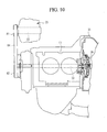
- FIG. 10 is a cross-sectional view partially showing a driving apparatus 10 according to another embodiment of the present invention.
- the electric generator 25 driven by the engine 13 is disposed parallel to the crankshaft 22 and above the engine 13.
- a driving pulley 82 linked to the crankshaft 22 is provided in front of the engine 13, and a driven pulley 83 fixed to the power-generating rotor 23 is provided above the driving pulley 82.
- An electric-power-generating power transmission member, that is, a driving belt 84 is bridged between the driving pulley 82 and the driven pulley 83, and the crankshaft 22 of the engine 13 indirectly drives the electric generator 25 through the driving belt 84.
- the electric generator 25 it is possible to dispose the electric generator 25 outside the gear case 21 and to shorten longitudinally the gear case 21 up to a dimension of the electric generator 25, whereby miniaturization of the driving apparatus 10 and improvement in further mounting characteristics can be achieved.
- a driving chain may be used instead of the driving belt 84.
- a driving sprocket is mounted on the crankshaft 22 instead of the driving pulley 82 and a driven sprocket is mounted on the power-generating rotor 23 instead of the driven pulley 83.
- the electric generator 25 may be driven by providing the driving gear and the driven gear. Note that the transmission in FIG. 10 is omitted and the transmissions 36 shown in the FIGs. 2 to 5 can be employed respectively as the omitted transmission.
- FIGs. 11A to 11F each is a skeleton view showing the driving apparatus 10 according to another embodiment of the present invention.
- the motor-side input axle 19 is linked axially to the output axle 20.
- the motor-side driving gear 31 and the motor-side driven gear 33 which link the motor-side input axle 19 and the output axle 20 and are shown in FIG. 2.
- the motor-side input axle 19 is linked axially to the engine-side input axle 18.
- the motor-side input axle 19 is linked axially to the engine-side input axle 18.
- Such elimination of the gears allows the driving apparatus 10 to be further miniaturized and, at the same time, the driving apparatus 10 to be made lighter in weight and lower in cost.
- the motor-side input axle 19 is disposed between the engine-side input axle 18 and the output axle 20 and parallel to them, and the driving gear 31 fixed to the motor-side input axle 19 is engaged with: the driving gear 30 provided on the engine-side input axle 18; and the driven gear 32 provided on the output axle 20.
- the driving gear 31 fixed to the motor-side input axle 19 is engaged with: the driving gear 30 provided on the engine-side input axle 18; and the driven gear 32 provided on the output axle 20.
- the respective input axles 18 and 19 and output axle 20 may be disposed so that the driving gear 30 of the engine-side input axle 18 and the driven gear 32 of the output axle 20 are directly engaged as shown in FIG. 2 and the driving gear 31 of the motor-side input axle 19 is directly engaged with the driving gear 30 of the engine-side input axle 18.
- the transmission 36 is incorporated between the driven gear 32 engaged with the driving gear 30 of the engine-side input axle 18 and the output axle 20.
- the clutch is incorporated in the transmission 36, and the transmission 36 has a function as a clutch.
- the clutch may be separated from the transmission 36 and be disposed.
- the transmission 36 is a belt type continuously variable transmission.
- a clutch 85 for shifting them to a directly connecting state or a disconnecting state is separated from the transmission 36 and is provided.
- a power transmission element 88 such as a metal belt or a metal chain is bridged between a groove-width-variable primary pulley 86 provided on the second input axle 18b and a groove-width-variable secondary pulley 87 provided on the output axle 20. Therefore, a continuously variable transmission may be used as the transmission 36 or the clutch 85 may be attached to the engine-side input axle 18 so as to separate the transmission 36.
- the transmission 36 is provided on the engine-side input axle 18, and there is provided, to the output axle 20, the clutch 85 for shifting a state of transmitting the engine power to the driving-wheels 17 or a power cutoff state of not transmitting it.
- FIG. 12 is a cross-sectional view showing a concrete example of the clutch 85 provided on the output axle 20 as shown in FIG. 11F.
- a cylindrical clutch hub 90 is fixed to a side surface of the engine-side driven gear 32, and a clutch drum 91 disposed outside a radial direction of the clutch hub 90 is fixed to the output axle 20.
- a plurality of clutch plates 90a are slidably mounted axially outside the radial direction of the clutch hub 90, and a plurality of clutch plates 91a, coming respectively in contact with the clutch plates 90a, are slidably mounted axially inside the radial direction of the clutch drum 91.
- a hydraulic piston 92 is slidably mounted axially on the clutch drum 91.
- a hydraulic chamber 93 constituted by the hydraulic piston 92 and the clutch drum 91
- the clutch plates 90a and 91a are operatively connected to one another.
- An oil pump 94 is incorporated in the gear case 21, and an inner rotor 95 of the oil pump 94 is attached to the output axle 20.
- FIGs. 13A is a cross-sectional view showing another concrete example of the clutch 85 shown in FIG. 11F
- FIG. 13B is cross-sectional view taken along line A-A in FIG. 13A
- the clutch 85 is an electromagnetic type two-way clutch, and comprises an outer ring 97 fixed to the engine-side driven gear 32 and an inner ring 98 fixed to the output axle 20.
- a plurality of cylindrical rollers 100 are disposed between the outer ring 97 and the inner ring 98, and the respective rollers 100 are held by a holder 99.
- An inner circumferential surface of the outer ring 97 facing the respective rollers 100 is formed cylindrically while an outer circumferential surface of the inner ring 98 is formed into a polygonal shape.
- the distance between the inner circumferential surface of the outer ring 97 and the outer circumferential surface of the inner ring 98 changes depending on positions disposed in a circumferential direction, and the longest distance is set to become longer than an outside dimension of each roller 100.
- a drive plate 101 fixed to the outer ring 97 and a driven plate 102 fixed to the holder 99 are mutually faced and a coil 103 disposed to face the drive plate 101 is fixed to the gear case 21.
- a switch spring 104 provided between the inner ring 98 and the holder 99 holds the inner ring 98 and the rollers 100 at a positioning relation in which the rollers 100 come in no contact with both of the inner ring 98 and the outer ring 97 and which is shown in FIG. 13B. Therefore, when no current flows to the coil 103, the outer ring 97 becomes rotatable with respect to the inner ring 98, without intruding into the inner ring 98 through the rollers 100. Meanwhile, a current flows to the coil 103, the outer ring 97 and the holder 98 are integrally rotated since the driven plate 102 draws the drive plate 101.
- the rollers 100 are engaged between the outer circumferential surface of the inner ring 98, that is, a cam surface and the inner circumferential surface of the outer ring 97, whereby the outer ring 97 is integrally rotated along with the inner ring 98 in all rotating directions. Accordingly, the clutch is shifted to the power transmission state at the time of the flow of the current to the coil 103 while to the power cutoff state at the time of the flow of no current to the coil 103.
- the transfer channels of the engine power can be easily sifted. Further, since lubrication of the inner ring 98, the outer ring 97, and the rollers 100 is sufficiently achieved by splashing a lubricant by the hypoid gear 35, it is unnecessary to provide an oil pump for lubrication. Additionally, it is unecessary to increase the kinds of lubricant based in the gear case 21, so that the driving apparatus 10 can have a simple structure. Further, dragging torque in the power cutoff state can be suppressed so as to become smaller. Note that an electromagnetic clutch may be used as the clutch 85 instead of the electromagnetic type two-way clutch shown in FIG. 13. Note that, through the above-mentioned respective embodiments, members having the same function are denoted by the same reference symbol.
- each of the driving apparatuses 10 shown in the drawings is applied to a front-wheel drive vehicle, but can be applied to a rear-wheel drive vehicle by transmitting power to rear wheels through the output axle 20 and applied to a four-wheel drive vehicle by transmitting power of the output axle 20 to rear wheels through a power transfer.
- each of the driving apparatuses 10 shown in the drawings is arranged parallel to the vehicle, but may be transversally arranged toward a width direction of the vehicle.
- the transmission is provided to the engine-power transfer channel, so that, by changing the gear ratio when the vehicle travels with a low speed and heavy load, an engine output can be enhanced to drive the vehicle.
- the clutch for shifting the power transmission state of transmitting the engine power to the driving-wheels and the power cutoff state of not transmitting is provided to the engine-power transfer channel, and so the engine power and the motor power can be selectively transmitted to the output axle and power required for the motor is suppressed, whereby the driving apparatus can be miniaturized.
Landscapes
- Engineering & Computer Science (AREA)
- Mechanical Engineering (AREA)
- Transportation (AREA)
- Chemical & Material Sciences (AREA)
- Combustion & Propulsion (AREA)
- General Engineering & Computer Science (AREA)
- Automation & Control Theory (AREA)
- Arrangement Of Transmissions (AREA)
- Electric Propulsion And Braking For Vehicles (AREA)
- Hybrid Electric Vehicles (AREA)
Abstract
Description
- The present invention relates to a driving apparatus for an electric vehicle and, particularly, to a technique effectively applied to the driving apparatus for an electric vehicle, which is driven by a plurality of power sources.
- An electric vehicle includes a battery accumulating power and a motor driving driving-wheels, and can travel by the power from the charged battery. The electric vehicle has advantages of emitting no exhaust fumes during vehicle running, good energy efficiency, and the like while it has the problems that mileage per charge is short and charging time for the battery is long and a troublesome charging operation is required.
- To solve these problems, a so-called hybrid vehicle has been developed as an electric vehicle equipped with an internal combustion engine such as a gasoline engine, a diesel engine, or the like in addition to a motor. In driving systems of the hybrid vehicles, there are a series type, a parallel type, and a series-parallel type. The electric vehicle of a series type is such that the battery is charged up to a value of power generated through an electric generator driven by an engine and the vehicle is driven by a motor. Since the engine is used to generate electric power, it can always be operated at an efficient revolution speed (for example, see Japanese Patent Laid-open (TOKUKAIHEI) No. 10-285708). The electric vehicle of a parallel type is such that an engine is mainly used as a drive source for vehicle running and drive power is assisted by the motor at the time of starting and/or acceleration at which the vehicle is subjected to heavy loads. When the vehicle is subjected to light loads due to bad engine efficiency, the function of the motor is changed to an electric generator to charge the battery.
- Meanwhile, the electric vehicle of a series-parallel type has an electric generator in'addition to an engine and a motor. The drive of the vehicle is changed to any one of drive by the engine, drive by the motor, and drive by both drive sources depending on running states, thereby allowing the engine and motor to be used under efficient conditions. In the electric vehicle having the driving system, the motor is used to drive the vehicle at the time of starting at which drive torque is required,and the vehicle is driven by the engine when its speed is increased, and the vehicle is driven by the motor and engine at the time of a uphill run at which it is subjected to heavy loads,and electric power is generated during the vehicle run when the engine is subjected to light load (for example, see Japanese Patent Laid-open (TOKUKAIHEI) No. 9-226393).
- However, in the conventional hybrid type electric vehicle, when the vehicle is driven by the motor, use of the motor with large output is required to satisfy, through the driving of the motor, engine performance requested in a high speed range. This is because the motor has such a property that the drive torque starts decreasing when it exceeds a predetermined revolution speed. Meanwhile, when the vehicle is driven by the engine, the revolution speed of the engine is determined through the vehicle speed if the vehicle is driven in a state of holding, at a first converter drive position, power from the engine. Therefore, since the engine produces only output directly proportional to the revolution speed, it cannot generate sufficient output in accordance with the state of vehicle running. Accordingly, in the case of traveling at low vehicle speed under the condition of heavy loads of the vehicle run such as uphill travel or the like, due to low revolution speed of the engine, the engine cannot produce its output sufficiently and smooth running of the engine becomes difficult.
- An object of the present invention is to achieve miniaturization of a driving apparatus for an electric vehicle without enlarging a motor and, at the same time, improve its driving performance demonstrated at the time of traveling by an engine drive.
- A driving apparatus for an electric vehicle according to the present invention includes an electric generator driven by an engine and a motor for driving driving-wheels by using electric power from said electric generator, the driving apparatus comprising: an engine-side input axle linked to a crankshaft of said engine and driven by said engine; a motor-side input axle linked to a motor rotor of said motor and driven by said motor; an output axle linked to said engine-side input axle and said motor-side input axle and transmitting power to said driving-wheels; and a transmission provided in an engine-power transfer channel formed by said engine-side input axle and said output axle, and shifting a revolution speed of said engine-power transfer channel to a plurality of shift ranges.
- In the driving apparatus for an electric vehicle according to the present invention, said transmission may be a discontinuously variable transmission having at least two ranges of a high speed range and a low speed range. Further, said transmission may be a continuously variable transmission whose a gear ratio is continuously shiftable.
- In the driving apparatus for an electric vehicle according to the present invention, said transmission may be provided with a clutch shifting to a power transmission state of transmitting engine power to said driving-wheels and a power cutoff state of not transmitting. Further, a clutch, shifting to a power transmission state of transmitting engine power to said driving-wheels and a power cutoff state of not transmitting, may be provided on said engine-side input axle so as to be separated from said transmission. Additionally, a clutch, shifting to a power transmission state of transmitting engine power to said driving-wheels and a power cutoff state of not transmitting, may be provided on said output axle so as to be separated from said transmission. Furthermore, a clutch, shifting to a power transmission state of transmitting engine power to said driving-wheels and a power cutoff state of not transmitting, may be provided between said output axle and a power transmission member linking said engine-side input axle and said output axle.
- In the driving apparatus for an electric vehicle according to the present invention, a power-generating rotor of said electric generator may be attached to said crankshaft, and said power-generating rotor may be directly driven by said crankshaft. Further, a power-generating rotor of said electric generator may be arranged parallel to said crankshaft, and said power-generating rotor may be indirectly driven through an electric-power-generating power transmission member by said crankshaft.
- In the driving apparatus for an electric vehicle according to the present invention, said motor-side input axle may be coaxially arranged on said engine-side input axle, and said engine-side input axle and said output axle may be linked through a power transmission member. Further, said motor-side input axle may be coaxially arranged on said output axle, and said engine-side input axle and said output axle may be linked through a power transmission member.
- In the driving apparatus for an electric vehicle according to the present invention, said engine-side input axle and said motor-side input axle may be provided parallel to said output axle, and said engine-side input axle and said output axle may be linked through a first power transmission member, and said motor-side input axle and said output axle may be linked through a second power transmission member. Further, said engine-side input axle, said motor-side input axle, and said output axle may be disposed parallel to one another, and said engine-side input axle and said motor-side input axle may be linked to said output axle through a power transmission member.
- The driving apparatus for an electric vehicle according to the present invention may further comprise: a velocity detecting means for detecting a traveling speed of the vehicle; and a clutch controlling means for setting said engine-power transfer channel to a power transmission state when the traveling speed of the vehicle exceeds a predetermined traveling speed.
- The driving apparatus for an electric vehicle according to the present invention may comprise: a load detecting means for detecting a traveling load of the vehicle; and a clutch controlling means for setting said engine-power transfer channel to a power transmission state when the traveling load of the vehicle exceeds a predetermined load, and may further comprise a shift controlling means for changing a gear ratio of said transmission based on the traveling load of the vehicle when said engine-power transfer channel is in a power transmission state. Additionally, the driving apparatus may comprise a motor controlling means for controlling power of said motor based on said traveling speed or a traveling load.
- In the driving apparatus for an electric vehicle according to the present invention, the transmission for changing the revolution speed of the engine-power transfer channel to the plurality of shift ranges is provided to the engine-power transfer channel, so that, by changing the gear ratio when the vehicle travels with a low speed and heavy load, an engine output can be enhanced to drive the vehicle. The clutch for shifting the power transmission state of transmitting the engine power to the driving-wheels and the power cutoff state of not transmitting is provided to the engine-power transfer channel, so that the engine power and the motor power can be selectively transmitted to the output axle and power required for the motor is suppressed, whereby the driving apparatus can be miniaturized.
- By way of example only, specific embodiments of the present invention will now be described with reference to the accompanying drawings, in which:-
- FIG. 1 is a schematic view showing a position of mounting, on a vehicle, a driving apparatus for an electric vehicle according to an embodiment of the present invention.
- FIG. 2 is a skeleton view showing a driving apparatus according to an embodiment of the present invention.
- FIG. 3 is a cross-sectional view of the driving apparatus shown in FIG. 2.
- FIG. 4 is a skeleton view showing a driving apparatus according to another embodiment of the present invention.
- FIG. 5 is a skeleton view showing a driving apparatus according to still another embodiment of the present invention.
- FIG. 6 is a block view showing a control circuit for controlling an operation of the driving apparatus.
- FIG. 7 is a flow chart showing a shift controlling procedure, which controls a clutch for shifting engine power to a power transmission state or power cutoff state with respect to driving-wheels.
- FIG. 8 is a flow chart showing a shift controlling procedure for shift ranges of a transmission.
- FIG. 9A is a skeleton view showing a transfer channel of power in a traveling state.
- FIG. 9B is a skeleton view showing a transfer channel of power in a traveling state.
- FIG. 9C is a skeleton view showing a transfer channel of power in a traveling state.
- FIG. 10 is a cross-sectional view showing partially a driving apparatus according to still another embodiment of the present invention.
- FIG. 11A is a skeleton view showing a driving apparatus according to another embodiment of the present invention.
- FIG. 11B is a skeleton view showing a driving apparatus according to another embodiment of the present invention.
- FIG. 11C is a skeleton view showing a driving apparatus according to another embodiment of the present invention.
- FIG. 11D is a skeleton view showing a driving apparatus according to another embodiment of the present invention.
- FIG. 11E is a skeleton view showing a driving apparatus according to another embodiment of the present invention.
- FIG. 11F is a skeleton view showing a driving apparatus according to another embodiment of the present invention.
- FIG. 12 is a cross-sectional view showing partially a driving apparatus incorporating a wet type multi-plate clutch.
- FIG. 13A is a cross-sectional view showing a driving apparatus incorporating a electromagnetic type two-way clutch.
- FIG. 13B is a cross-sectional view taken along line A-A shown in FIG. 13A.
-
- Embodiments of the present invention will be detailed below based on the drawings. As shown in FIG. 1, a driving
apparatus 10 is parallel mount on a front end of an electric vehicle, namely, ahybrid vehicle 11, and accessories such as aradiator 12 and the like are provided in front of the drivingapparatus 10. A front end of the drivingapparatus 10 is provided with anengine 13, and a rear end thereof is provided with amotor 14, and apower transmission section 15 is provided between theengine 13 and themotor 14. A front-wheel-drive axle 16 protruding from thepower transmission section 15 in the widthwise direction of the vehicle is linked to front wheels, namely, driving-wheels 17, and the drivingapparatus 10 is applied to thehybrid vehicle 11 of a front-wheel-drive type. - As shown in FIGs. 2 and 3, the
power transmission section 15 comprises: an engine-side input axle 18 driven by theengine 13; a motor-side input axle 19 driven by themotor 14; and anoutput axle 20 linked to the front wheels, namely, the driving-wheels 17 in parallel to theseaxles side input axle 18, motor-side input axle 19, andoutput axle 20 are rotatably housed in agear case 21 toward an advancing direction of the vehicle. Thegear case 21 is constituted by a plurality of case bodies, and thegear case 21 is assembled by fixing the plurality of case bodies by means of bolts. - A cylindrical power-generating
rotor 23 is linked to acrankshaft 22 of theengine 13, and astator 24 disposed so as to surround the power-generatingrotor 23 is fixed to thegear case 21, and astator coil 24a is wound around thestator 24. The power-generatingrotor 23 and thestator 24 constitute a generator, namely, anelectric generator 25. The power-generatingrotor 23 is directly driven by thecrankshaft 22, that is, driven without interposing power transmission members such as gears and belts, etc., thereby allowing efficient electric power to be generated without causing power transmission losses. Adamper 26 for attenuating engine power of thecrankshaft 22 and transmitting the attenuated power to the engine-side input axle 18 is incorporated in an accommodating space formed inside the power-generatingrotor 23. Theengine 13 drives the power-generatingrotor 23 and the engine-side input axle 18. - The
motor 14 is incorporated in amotor case 27 linked to thegear case 21, and includes acylindrical stator 28 fixed to themotor case 27 and amotor rotor 29 rotatably incorporated inside thestator 28, wherein astator coil 28a is wound around thestator 28. Themotor 14 is constituted by thestator 28 and themotor rotor 29. Themotor rotor 29 is driven by supplying electric power to thestator coil 28. Further, the motor-side input axle 19 is linked to a tip of themotor rotor 29 protruding from themotor case 27, and themotor 14 drives the motor-side input axle 19. - The engine-
side input axle 18 comprises: afirst input axle 18a linked to thecrankshaft 22 through thedamper 26; and asecond input axle 18b disposed concentrically thereto, wherein a engine-side driving gear 30 is provided on thesecond input axle 18b and a motor-side driving gear 31 is provided on the motor-side input axle 19. On theoutput axle 20, an engine-side drivengear 32 and a motor-side drivengear 33 are provided so as to be engaged with these drivinggears side driving gear 30 and drivengear 32 forms a first power transmission member while a gear train comprising the motor-side driving gear 31 and drivengear 33 forms a second power transmission member. - A
hypoid pinion gear 34, which is a final reduction drive gear, is provided on theoutput axle 20, and ahypoid gear 35, which is a final reduction driven gear as engaged therewith, is rotatably provided in thegear case 21. Thehypoid gear 35 has a differential gear unit not shown, namely, a differential gear, whereby power transmitted to theoutput axle 20 from the engine-side input axle 18 and the motor-side input axle 19 is input to thehypoid gear 35 and, thereafter, is transmitted to the left and right front-wheel-drive axles 16 through the differential gear. - Thus, in the driving
apparatus 10, an engine-power transfer channel 40a, transmitting the engine power to the driving-wheels 17, is formed by: the engine-side input axle 18 comprising the first andsecond input axles output axle 20 linked to the engine-side input axle through the gear train. A motor-power transfer channel 40b is formed by the motor-side input axle 19 and theoutput axle 20 linked to it through the gear train. Therefore, the power is transmitted to the driving-wheels 17 through either or both of the power transfer channels. - On the engine-
side input axle 18 constituting the engine-power transfer channel 40a, atransmission 36 is provided to change the revolution speed of the engine-power transfer channel 40a at two stages by shifting the revolution speed of thefirst input axle 18a to that of thesecond input axle 18b. Therefore, thetransmission 36 becomes parallel to the engine-side input axle 18 and includes aintermediate axle 37 provided in thegear case 21. There are rotatably mounted, on theintermediate axle 37, first and secondintermediate gears driving gear 38 fixed to thefirst input axle 18a and a drivengear 39 rotatably mounted on thesecond input axle 18b. Theseintermediate gears - A changing
hub 43 is spline-connected to thesecond input axle 18b, and a changingsleeve 44 is axially and slidably engaged with the changinghub 43. Aclutch gear 38a, engaged with the changingsleeve 44, is provided to thedriving gear 38 while aclutch gear 39a, engaged with the changingsleeve 44, is provided to the drivengear 39. Therefore, the changingsleeve 44 is automatically driven axially by a hydraulic type actuator not shown. A dog clutch type shift mechanism is formed by the changingsleeve 44, but a synchromesh type shift mechanism may be used. - When the changing
sleeve 44 is engaged with thedriving gear 38 through theclutch gear 38a, the first andsecond input axles second input axle 18b is equal to that of thecrankshaft 22 to transmit the engine power to the driving-wheels 17 through theoutput axle 20. Meanwhile, when the changingsleeve 44 is engaged with the drivengear 39 through theclutch gear 39a, thefirst input axle 18a is linked to thesecond input gear 18b through a shift gear train comprising thedriving gear 38, the drivengear 39, and theintermediate gears second input axle 18b becomes different from that of thefirst input gear 18a to transmit the engine power to the driving-wheels 17 through theoutput axle 20. Thedriving gear 38 has a diameter smaller than the drivengear 39 and, therefore, rotation of thecrankshaft 22 is reduced when the engine power is transmitted to the driving-wheels 17 through the shift gear train. Accordingly, thetransmission 36 has a gear ratio of a high speed range when the first andsecond input axles transmission 36 has a gear ratio of a low speed range when bothinput axles - The changing
sleeve 44 moves at an intermediate position at which neither of thedriving gear 38 and the drivengear 39 are connected to the changing sleeve, and the changingsleeve 44 functions as a clutch for shifting a power transmission state of transmitting the engine power to theoutput axle 20 and a power cutoff state of not transmitting it. - FIG. 4 is a skeleton view showing a driving
apparatus 10 according to another embodiment of the present invention. This drivingapparatus 10 is different from the above-mentioned driving apparatus in a structure of thetransmission 36, but is otherwise the same as in the other structures. Atransmission 36 is shown in FIG.4 of the planet gear type. Asun gear 46 is attached to aclutch hub 45 rotatably mounted on thefirst input axle 18a, and aring gear 48 is attached to aclutch hub 47 fixed to thesecond input axle 18b. Apinion gear 51a engaged with thesun gear 46, and apinion gear 51b engaged with thispinion gear 51a and thering gear 48 are rotatably mounted on acarrier 49 fixed to thefirst input axle 18a, respectively. The planet gear is of the double pinion type. - A
clutch drum 52 is disposed outside theclutch hub 45, and theclutch drum 52 is fixed to thegear case 21. A plurality ofclutch plates 52a are slidably mounted axially inside a radial direction of theclutch drum 52, andclutch plates 45a coming in contact with theclutch plates 52a are slidably mounted axially outside a radial direction of theclutch hub 45. Therefore, the clutch 53a is constituted by these clutch plates. An annularhydraulic piston 54 is mounted on theclutch drum 52, and ahydraulic chamber 55 is constituted by thehydraulic piston 54 and theclutch drum 52. When working fluid is supplied into thehydraulic chamber 55, theclutch plates sun gear 46 becomes a fixed state. Meanwhile, when the connecting state of theclutch plates sun gear 46 can be rotated. - The
clutch drum 56 is disposed outside theclutch hub 47, and theclutch drum 56 is attached to thecarrier 49. A plurality ofclutch plates 56a are slidably mounted axially inside a radius direction of theclutch drum 56 whileclutch plates 47a coming in contact with theclutch plates 56a are slidably mounted axially outside a radius direction of theclutch hub 47. Therefore, the clutch 53b is constituted by these clutch plates. A cylindricalhydraulic piston 57 is mounted on theclutch drum 56, and ahydraulic chamber 58 is formed by thehydraulic piston 57 and theclutch drum 56. When working fluid is supplied into thehydraulic chamber 58, theclutch plates carrier 49 and thering gear 48 are operatively connected to each other. Meanwhile, when the operatively connected state of theclutch plates carrier 49 and thering gear 48 become relatively rotatable. - In the
transmission 36 shown in FIG. 4, when the clutch 53a is set in a released state and the clutch 53b is set in an operatively connected state, thefirst input axle 18a and thesecond input axle 18b become directly connected through thecarrier 49 and theclutch hub 47 operatively connected thereto. Therefore, the revolution speed of thesecond input axle 18b is equal to that of thecrankshaft 22, whereby the engine power is transmitted to the driving-wheels 17 through theoutput axle 20. Meanwhile, when the clutch 53a is set in an operatively connected state and the clutch 53b is set in a released state, the rotation of thefirst input axle 18a is transmitted to thesecond input axle 18b through the pinion gears 51a and 51b and thering gear 48. Therefore, the revolution speed of thesecond input axle 18b becomes slower than that of thecrankshaft 22 and is transmitted to theoutput axle 20. Accordingly, when the first andsecond input axle transmission 36 obtains a gear ratio of a high speed range. When the clutch 53a is operatively connected, the rotation of thefirst input axle 18a is reduced through the pinion gears 51a and 51b and is transmitted to thesecond input axle 18b and thetransmission 36 obtains a gear ratio of a low speed range. - Additionally, when both of the two
clutches first input axle 18a and thesecond input axle 18b become cutoff states and the engine power is not transmitted to theoutput axle 20, whereby theseclutches wheels 17 through theoutput axle 20 and a power cutoff state of not transmitting it. - FIG. 5 is a skeleton view showing a driving
apparatus 10 according to another embodiment of the present invention. In this drivingapparatus 10, thetransmission 36 is different from that of the above-mentioned driving apparatus in structure and the engine-side input axle 18 is formed by an integrally rotating shaft, but the other structures except the transmission and the engine-side input axle are the same. Thetransmission 36 shown in FIG. 5 is formed by a shift gear train provided with a clutch, which shifts to the respective power transmission state and power cutoff state. Afirst driving gear 59a is rotatably mounted on the engine-side input axle 18 and asecond driving gear 60a is fixed to the engine-side input axle 18. A drivengear 59b, forming ashift gear train 59 by being always engaged with thedriving gear 59a, is fixed to theoutput axle 20, and a drivengear 60b, forming ashift gear train 60 by being always engaged with thedriving gear 60a, is rotatably mounted on theoutput axle 20. - The engine-
side input axle 18 is provided with a clutch 61a for shifting theshift gear train 59 to the power transmission state or power cutoff state, and theoutput axle 20 is provided with a clutch 61b for shifting theshift gear train 60 to the power transmission state or power cutoff state. The clutch 61a has aclutch drum 62 fixed to the engine-side input axle 18, and aclutch hub 63 fixed to thedriving gear 59a. A plurality ofclutch plates 62a are slidably mounted axially inside a radial direction of theclutch drum 62, andclutch plates 63a coming respectively in contact with theclutch plates 62a are slidably mounted axially outside a radial direction of theclutch hub 63. An annularhydraulic piston 64 is mounted on theclutch drum 62, whereby ahydraulic chamber 65 is constituted by thehydraulic piston 64 and theclutch drum 62. When working fluid is supplied into thehydraulic chamber 65, theclutch plates driving gear 59a is operatively connected to the engine-side input axle 18 and theshift gear train 59 becomes the power transmission state. - The clutch 61b has a
clutch drum 66 fixed to theoutput axle 20, and aclutch hub 67 fixed to the drivengear 60b. Similarly to the clutch 61a,clutch plates hydraulic piston 68 is mounted on theclutch drum 66. When the working fluid is supplied into ahydraulic chamber 69 constituted by thehydraulic piston 68 and theclutch drum 66, theclutch plates driving gear 60a is operatively connected to theoutput axle 20 and theshift gear train 60 becomes the power transmission state. - The
driving gear 59a has a radius smaller than that of thedriving gear 60a. When the clutch 61a is in the operatively connected state and theshift gear train 59 becomes the power transmission state, thetransmission 36 has a gear ratio of a low speed range. When the clutch 61b becomes operatively connected and theshift gear train 60 becomes the power transmission state, the transmission has a gear ratio of a high speed range. Further, bothclutches output axle 20 is blocked. - Each of the
transmissions 36 shown in FIGs. 2 to 5 is a discontinuously variable transmission having a two-step shift range comprising a high speed range and a low speed range. However, the step number of the shift range is not limited to two steps and the above-mentioned transmission may have a three or more-step shift range. - FIG. 6 is a block view showing a control circuit for controlling an operation of the above-mentioned
driving apparatus 10, wherein there are transmitted, to amain controller 70, detection signals from: anaccelerator opening sensor 71 for detecting an opening angle of an accelerator pedal; avelocity sensor 72 as a velocity detecting means for detecting a traveling speed of a vehicle; aloading sensor 73 comprising a throttle opening sensor or the like as a load detecting means for detecting traveling loads of the vehicle; a motor revolution-speed sensor 74 for detecting revolution speed of themotor rotor 29; and an engine revolution-speed sensor 75 for detecting revolution speed of thecrackshaft 22. Respective control signals output from themain controller 70 are transmitted to: anengine controller 76 for controlling an operation of theengine 13; amotor controller 77 as a motor controlling means for controlling an operation of themotor 14; anelectric generator controller 78 for controlling an operation of theelectric generator 25; atransmission controller 79 as a shift controlling means for controlling a shift of the shift ranges by thetransmission 36; and aclutch controller 80 as a clutch controlling means for controlling a shift of the clutch incorporated in thetransmission 36. - A
battery 81 is connected to themotor controller 77 and theelectric generator controller 78. If the vehicle is driven by themotor 14, electric power from thebattery 81 is supplied to astator coil 28a of themotor 14. Meanwhile, charging of thebattery 81 is performed by working theelectric generator 25, but themotor 14 may charge thebattery 81 by using a function of themotor 14 as an electric generator during braking thereof. - In the driving
apparatus 10 shown in FIG. 2, the changingsleeve 44 is driven by the hydraulic actuator to achieve the shifting of the shift range and the blocking of power, so that the operation of the hydraulic actuator is controlled by a signal from thetransmission controller 79 and the changingsleeve 44 is driven. Meanwhile, in each driving apparatus shown in FIGs. 4 and 5, the shifting of the shift range and the blocking of the power are achieved by controlling hydraulic pressure supplied to the hydraulic chamber of the clutch, so that the signal from theclutch controller 80 controls the hydraulic pressure supplied to the hydraulic chamber. When the blocking of power transmission, that is, the transmission and the blocking of the engine power, and made by the clutch separated from thetransmission 36 and when only the controlling of the gear ratio is made by thetransmission 36, the transmission is controlled by thetransmission controller 79 and the clutch is controlled by theclutch controller 80. - FIG. 7 is a flow chart showing a shift controlling procedure for controlling a clutch for shifting engine power to a power transmission state or power cutoff state with respect to driving-wheels, and FIG. 8 is a flow chart showing a shift controlling procedure for shift ranges of a transmission. Each process is performed per predetermined time, for example, per 10 msec.
- In step S1, a traveling speed VSP detected by the
velocity sensor 72 and a determination threshold VSPS1 (for example, 80 km/h) stored in a memory in themain controller 70 are compared. If it is determined that the traveling speed VSP does not reach the determination threshold VSPS1, step S2 determines a throttle opening angle THV as an example of a load. In the step S2, the throttle opening angle THV detected by the loading sensor (the throttle opening angle sensor) 73 and a determination threshold THVS (for example, 30 degrees) stored in the memory are compared. If it is determined that the throttle opening angle THV does not reach the determination threshold THVS, step S3 is performed. When the step S3 is performed, the clutch is released and the transmission of the engine power to theoutput axle 20 is blocked, whereby the vehicle is driven by themotor 14. - Meanwhile, when it is determined in the step S1 that the traveling speed is higher than the determination threshold VSPS1 or in the step S2 that the throttle opening angle is larger than the determination threshold and the vehicle is driven with heavy loads, step S4 is performed and the clutch becomes operatively connected, whereby the vehicle is driven by the engine power.
- Note that, in the present embodiment, a load state is determined by the throttle opening angle, but, as well known, there may be appropriately adopted an accelerator opening angle, an intake of air into the engine, a fuel-injection pulse width determining an amount of fuel injected through a fuel-injection valve of the engine or a basic fuel-injection pulse width determining a basic amount of fuel injected, an intake of air per stroke of the engine, and an intake of air per turn of the engine, etc. in order to determine the load state instead of the throttle opening angle.
- In step S5 shown in FIG. 8, it is determined whether or not the clutch is operatively connected, that is, whether the clutch is operatively connected to engine-travel the vehicle or whether the clutch is released to motor-travel the vehicle. If it is determined that the vehicle is engine-traveled, the traveling speed VSP detected by the
velocity sensor 72 and a determination threshold VSPS2 (for example, 50 km/h) stored in the memory are compared in step S6. If it is determined that the traveling speed VSP does not reach the determination threshold VSPS2, thetransmission 36 is shifted to a low speed rage in step S7. When the traveling speed exceeds the determination threshold VSPS2, thetransmission 36 is shifted to a high speed range in step S8. - FIG. 9 is a skeleton view showing a transfer channel of the power in the above-mentioned
driving apparatus 10. FIG. 9A shows the transfer channel of the power at the time of a low-speed and low-load run in which the traveling speed is equal to or less than the predetermined value VSPS1 and the throttle opening angle is equal to or less than the predetermined value THVS. At this time, the clutch incorporated in thetransmission 36 is shifted to a power cutoff state and the motor power is transmitted to the driving-wheels 17 through a motor-power transfer channel 40b. Therefore, at the time of the traveling under this condition, theengine 13 can be driven with good efficient revolution speed, and thebattery 81 is charged through theelectric generator 25 driven by theengine 13 and, at the same time, the electric power is supplied to themotor 14 from thebattery 81. - FIG. 9B shows a transfer channel of power during high speed running or a heavy load run in which the traveling speed is equal to or more than a predetermined traveling speed. At this time, the clutch incorporated in the
transmission 36 is shifted to the power transmission state and the driving-wheels 17 are driven through the engine-power transfer channel 40a by using theengine 13 as a power source. At the time of the traveling under this condition, the supplying of the power to themotor 14 is blocked, whereby the traveling, which uses only theengine 13 as a power source, is made. During heavy-load running, which uses the engine as a power source and in which the throttle opening angle is equal to or more than a predetermined value, the shift range of thetransmission 36 is shifted to either of a low speed range and a high speed range depending on the traveling speed. Therefore, when the vehicle with an approximately 40km/h low speed travels an uphill road, the revolution speed of the engine is increased by shifting the shift range to a low speed range and a large engine output is transmitted to the driving-wheels 17 so as to travel by only the engine power, whereby the driving performance of the vehicle can be improved. - FIG. 9(c) shows a state of driving the
motor 14 plus theengine 13 to transmit the engine power and the motor power to theoutput axle 20. In the traveling conditions where large drive torque is required, such as a rapid acceleration or uphill road run, the engine power and the motor power are transmitted to the driving-wheels 17 through the engine-power transfer channel 40a and the motor-power transfer channel 40b. Therefore, in the traveling condition where theengine 13 is under heavy load, since the motor power assisting the drive torque is also transmitted to theoutput axle 20, an output required for theengine 13 can be set to become small without reducing the driving performance of the vehicle, whereby theengine 13 can be miniaturized. Further, since the power source for driving the vehicle can be appropriately sifted depending on the traveling conditions, energy efficiency of the entire of the system of the drivingapparatus 10 can be improved. - Note that the control of the clutch incorporated in the
transmission 36 is similarly made also in shifting high speed running to low speed running. At this time, the traveling speed set in shifting the clutch to the power cutoff state is set to be smaller than that set in shifting the clutch to the power transmission state and, therefore, it is possible to prevent an occurrence of a hunting phenomenon in which the motor power and the engine power are frequently shifted in traveling at the nearly set traveling speed. - FIG. 10 is a cross-sectional view partially showing a driving
apparatus 10 according to another embodiment of the present invention. As shown in FIG. 10, theelectric generator 25 driven by theengine 13 is disposed parallel to thecrankshaft 22 and above theengine 13. A drivingpulley 82 linked to thecrankshaft 22 is provided in front of theengine 13, and a drivenpulley 83 fixed to the power-generatingrotor 23 is provided above the drivingpulley 82. An electric-power-generating power transmission member, that is, a drivingbelt 84 is bridged between the drivingpulley 82 and the drivenpulley 83, and thecrankshaft 22 of theengine 13 indirectly drives theelectric generator 25 through the drivingbelt 84. - In this case, it is possible to dispose the
electric generator 25 outside thegear case 21 and to shorten longitudinally thegear case 21 up to a dimension of theelectric generator 25, whereby miniaturization of the drivingapparatus 10 and improvement in further mounting characteristics can be achieved. As the electric-power-generating power transmission member, a driving chain may be used instead of the drivingbelt 84. In that case, a driving sprocket is mounted on thecrankshaft 22 instead of the drivingpulley 82 and a driven sprocket is mounted on the power-generatingrotor 23 instead of the drivenpulley 83. Further, as the electric-power-generating power transmission member, theelectric generator 25 may be driven by providing the driving gear and the driven gear. Note that the transmission in FIG. 10 is omitted and thetransmissions 36 shown in the FIGs. 2 to 5 can be employed respectively as the omitted transmission. - FIGs. 11A to 11F each is a skeleton view showing the driving
apparatus 10 according to another embodiment of the present invention. In the drivingapparatus 10 shown in FIG. 11A, the motor-side input axle 19 is linked axially to theoutput axle 20. Thus, by connecting directly the motor-side input axle 19 to theoutput axle 20, it is possible to eliminate the motor-side driving gear 31 and the motor-side drivengear 33, which link the motor-side input axle 19 and theoutput axle 20 and are shown in FIG. 2. - In the driving apparatus shown in FIG. 11B, the motor-
side input axle 19 is linked axially to the engine-side input axle 18. Thus, by connecting directly the motor-side input axle 19 to the engine-side input axle 18, it is possible to eliminate either of a pair of motor-side drivinginput axle 31 and motor-side driveninput axle 33 shown in FIG. 2 and a pair of engine-side driving gear 30 and engine-side drivengear 32. Such elimination of the gears allows the drivingapparatus 10 to be further miniaturized and, at the same time, the drivingapparatus 10 to be made lighter in weight and lower in cost. - In the driving
apparatus 10 shown in FIG. 11C, the motor-side input axle 19 is disposed between the engine-side input axle 18 and theoutput axle 20 and parallel to them, and thedriving gear 31 fixed to the motor-side input axle 19 is engaged with: the drivinggear 30 provided on the engine-side input axle 18; and the drivengear 32 provided on theoutput axle 20. Thereby, such an arrangement of theengine 13 and themotor 14 allows the drivengear 33 attached to theoutput axle 20 shown in FIG. 2 to be eliminated and allows the drivingapparatus 10 to be further miniaturized. Additionally, it is possible to increase a degree of freedom in disposing the engine-side input axle 18 and the motor-side input axle 19. - Further, as another modified example in FIG. 2, the
respective input axles output axle 20 may be disposed so that thedriving gear 30 of the engine-side input axle 18 and the drivengear 32 of theoutput axle 20 are directly engaged as shown in FIG. 2 and thedriving gear 31 of the motor-side input axle 19 is directly engaged with thedriving gear 30 of the engine-side input axle 18. - In the driving
apparatus 10 shown in FIG. 11D, thetransmission 36 is incorporated between the drivengear 32 engaged with thedriving gear 30 of the engine-side input axle 18 and theoutput axle 20. By such an arrangement, a degree of freedom in designing the power transfer channel can be enhanced. In each of the driving apparatus shown in FIGs. 11A to 11D, the clutch is incorporated in thetransmission 36, and thetransmission 36 has a function as a clutch. However, the clutch may be separated from thetransmission 36 and be disposed. - In the driving apparatus shown in FIG. 11E, the
transmission 36 is a belt type continuously variable transmission. Between thefirst input axle 18a and thesecond input axle 18b constituting the engine-side input axle 18, a clutch 85 for shifting them to a directly connecting state or a disconnecting state is separated from thetransmission 36 and is provided. Apower transmission element 88 such as a metal belt or a metal chain is bridged between a groove-width-variableprimary pulley 86 provided on thesecond input axle 18b and a groove-width-variablesecondary pulley 87 provided on theoutput axle 20. Therefore, a continuously variable transmission may be used as thetransmission 36 or the clutch 85 may be attached to the engine-side input axle 18 so as to separate thetransmission 36. - In the driving
apparatus 10 shown in FIG. 11F, thetransmission 36 is provided on the engine-side input axle 18, and there is provided, to theoutput axle 20, the clutch 85 for shifting a state of transmitting the engine power to the driving-wheels 17 or a power cutoff state of not transmitting it. - FIG. 12 is a cross-sectional view showing a concrete example of the clutch 85 provided on the
output axle 20 as shown in FIG. 11F. As shown in FIG. 12, a cylindricalclutch hub 90 is fixed to a side surface of the engine-side drivengear 32, and aclutch drum 91 disposed outside a radial direction of theclutch hub 90 is fixed to theoutput axle 20. A plurality ofclutch plates 90a are slidably mounted axially outside the radial direction of theclutch hub 90, and a plurality ofclutch plates 91a, coming respectively in contact with theclutch plates 90a, are slidably mounted axially inside the radial direction of theclutch drum 91. - A
hydraulic piston 92 is slidably mounted axially on theclutch drum 91. When working fluid is supplied to ahydraulic chamber 93 constituted by thehydraulic piston 92 and theclutch drum 91, theclutch plates oil pump 94 is incorporated in thegear case 21, and aninner rotor 95 of theoil pump 94 is attached to theoutput axle 20. In theoutput axle 20, there is formed anoil path 96 for guiding, to thehydraulic chamber 93, the working fluid discharged from theoil pump 94, and pressure of the working fluid supplied to thehydraulic chamber 93 is regulated by a regulating valve not shown. - FIGs. 13A is a cross-sectional view showing another concrete example of the clutch 85 shown in FIG. 11F, and FIG. 13B is cross-sectional view taken along line A-A in FIG. 13A. The clutch 85 is an electromagnetic type two-way clutch, and comprises an
outer ring 97 fixed to the engine-side drivengear 32 and aninner ring 98 fixed to theoutput axle 20. A plurality ofcylindrical rollers 100 are disposed between theouter ring 97 and theinner ring 98, and therespective rollers 100 are held by aholder 99. An inner circumferential surface of theouter ring 97 facing therespective rollers 100 is formed cylindrically while an outer circumferential surface of theinner ring 98 is formed into a polygonal shape. The distance between the inner circumferential surface of theouter ring 97 and the outer circumferential surface of theinner ring 98 changes depending on positions disposed in a circumferential direction, and the longest distance is set to become longer than an outside dimension of eachroller 100. Adrive plate 101 fixed to theouter ring 97 and a drivenplate 102 fixed to theholder 99 are mutually faced and acoil 103 disposed to face thedrive plate 101 is fixed to thegear case 21. - When no current flows to the
coil 103, aswitch spring 104 provided between theinner ring 98 and theholder 99 holds theinner ring 98 and therollers 100 at a positioning relation in which therollers 100 come in no contact with both of theinner ring 98 and theouter ring 97 and which is shown in FIG. 13B. Therefore, when no current flows to thecoil 103, theouter ring 97 becomes rotatable with respect to theinner ring 98, without intruding into theinner ring 98 through therollers 100. Meanwhile, a current flows to thecoil 103, theouter ring 97 and theholder 98 are integrally rotated since the drivenplate 102 draws thedrive plate 101. When theouter ring 97 and theholder 99 are rotation-moved, therollers 100 are engaged between the outer circumferential surface of theinner ring 98, that is, a cam surface and the inner circumferential surface of theouter ring 97, whereby theouter ring 97 is integrally rotated along with theinner ring 98 in all rotating directions. Accordingly, the clutch is shifted to the power transmission state at the time of the flow of the current to thecoil 103 while to the power cutoff state at the time of the flow of no current to thecoil 103. - Since the above-mentioned electromagnetic type two-way clutch can be shifted by controlling the flow of the current to the
coil 103, the transfer channels of the engine power can be easily sifted. Further, since lubrication of theinner ring 98, theouter ring 97, and therollers 100 is sufficiently achieved by splashing a lubricant by thehypoid gear 35, it is unnecessary to provide an oil pump for lubrication. Additionally, it is unecessary to increase the kinds of lubricant based in thegear case 21, so that the drivingapparatus 10 can have a simple structure. Further, dragging torque in the power cutoff state can be suppressed so as to become smaller. Note that an electromagnetic clutch may be used as the clutch 85 instead of the electromagnetic type two-way clutch shown in FIG. 13. Note that, through the above-mentioned respective embodiments, members having the same function are denoted by the same reference symbol. - The present invention is not limited to the above-mentioned embodiments and can be variously altered and modified without departing from the gist thereof. For example, each of the driving
apparatuses 10 shown in the drawings is applied to a front-wheel drive vehicle, but can be applied to a rear-wheel drive vehicle by transmitting power to rear wheels through theoutput axle 20 and applied to a four-wheel drive vehicle by transmitting power of theoutput axle 20 to rear wheels through a power transfer. Further, each of the drivingapparatuses 10 shown in the drawings is arranged parallel to the vehicle, but may be transversally arranged toward a width direction of the vehicle. - According to the present invention, the transmission is provided to the engine-power transfer channel, so that, by changing the gear ratio when the vehicle travels with a low speed and heavy load, an engine output can be enhanced to drive the vehicle. The clutch for shifting the power transmission state of transmitting the engine power to the driving-wheels and the power cutoff state of not transmitting is provided to the engine-power transfer channel, and so the engine power and the motor power can be selectively transmitted to the output axle and power required for the motor is suppressed, whereby the driving apparatus can be miniaturized.
- The entire disclosure of a Japanese Patent Application No. 2003-007954, filed on January 16, 2003 including specification, claims, drawings and summary, on which the Convention priority of the present application is based, are incorporated herein by reference in its entirety.
Claims (15)
- A driving apparatus for an electric vehicle including an electric generator driven by an engine and a motor for driving driving-wheels by using electric power from said electric generator, the driving apparatus comprising:an engine-side input axle linked to a crankshaft of said engine and driven by said engine;a motor-side input axle linked to a motor rotor of said motor and driven by said motor; andan output axle linked to said engine-side input axle and said motor-side input axle and transmitting power to said driving-wheels, characterized in that:a transmission is provided in an engine-power transfer channel formed by said engine-side input axle and said output axle, and shifting a revolution speed of said engine-power transfer channel to a plurality of shift ranges.
- The driving apparatus for an electric vehicle according to claim 1, wherein said transmission is a discontinuously variable transmission having at least two ranges of a high speed range and a low speed range.
- The driving apparatus for an electric vehicle according to claim 1, wherein said transmission is a continuously variable transmission whose a gear ratio is continuously shiftable.
- The driving apparatus for an electric vehicle according to any one of claims 1 to 3, wherein said transmission is provided with a clutch shifting to a power transmission state of transmitting engine power to said driving-wheels and a power cutoff state of not transmitting.
- The driving apparatus for an electric vehicle according to any one of claims 1 to 3, wherein a clutch, shifting to a power transmission state of transmitting engine power to said driving-wheels and a power cutoff state of not transmitting, is provided on said engine-side input axle or said output axle so as to be separated from said transmission.
- The driving apparatus for an electric vehicle according to any one of claims 1 to 3, wherein a clutch, shifting to a power transmission state of transmitting engine power to said driving-wheels and a power cutoff state of not transmitting, is provided between said output axle and said power transmission member linking said engine-side input axle and said output axle.
- The driving apparatus for an electric vehicle according to any one of claims 1 to 6, wherein a power-generating rotor of said electric generator is attached to said crankshaft, and said power-generating rotor is directly driven by said crankshaft.
- The driving apparatus for an electric vehicle according to any one of claims 1 to 6, wherein a power-generating rotor of said electric generator is arranged parallel to said crankshaft, and said power-generating rotor is indirectly driven through an electric-power-generating power transmission member by said crankshaft.
- The driving apparatus for an electric vehicle according to any one of claims 1 to 8, wherein said motor-side input axle is coaxially arranged on either of said engine-side input axle and said output axle, and said engine-side input axle and said output axle are linked through a power transmission member.
- The driving apparatus for an electric vehicle according to any one of claims 1 to 8, wherein said engine-side input axle and said motor-side input axle are provided parallel to said output axle, and said engine-side input axle and said output axle are linked through a first power transmission member, and said motor-side input axle and said output axle are linked through a second power transmission member.
- The driving apparatus for an electric vehicle according to any one of claims 1 to 8, wherein said engine-side input axle, said motor-side input axle, and said output axle are disposed parallel to one another, and said engine-side input axle and said motor-side input axle are linked to said output axle through a power transmission member.
- The driving apparatus for an electric vehicle according to any one of claims 1 to 11, further comprising:a velocity detecting means for detecting a traveling speed of the vehicle; anda clutch controlling means for setting said engine-power transfer channel to a power transmission state when the traveling speed of the vehicle exceeds a predetermined traveling speed.
- The driving apparatus for an electric vehicle according to any one of claims 1 to 12, further comprising:a load detecting means for detecting a traveling load of the vehicle; anda clutch controlling means for setting said engine-power transfer channel to a power transmission state when the traveling load of the vehicle exceeds a predetermined load.
- The driving apparatus for an electric vehicle according to any one of claims 1 to 13, further comprising a shift controlling means for changing a gear ratio of said transmission based on the traveling load of the vehicle when said engine-power transfer channel is in a power transmission state.
- The driving apparatus for an electric vehicle according to any one of claims 1 to 14, further comprising a motor controlling means for controlling power of said motor based on said traveling speed or a traveling load.
Applications Claiming Priority (2)
| Application Number | Priority Date | Filing Date | Title |
|---|---|---|---|
| JP2003007954A JP2004222435A (en) | 2003-01-16 | 2003-01-16 | Electric vehicle drive |
| JP2003007954 | 2003-01-16 |
Publications (2)
| Publication Number | Publication Date |
|---|---|
| EP1439086A2 true EP1439086A2 (en) | 2004-07-21 |
| EP1439086A3 EP1439086A3 (en) | 2006-08-30 |
Family
ID=32588522
Family Applications (1)
| Application Number | Title | Priority Date | Filing Date |
|---|---|---|---|
| EP04250193A Withdrawn EP1439086A3 (en) | 2003-01-16 | 2004-01-15 | Driving apparatus for an electric vehicle |
Country Status (3)
| Country | Link |
|---|---|
| US (1) | US7191859B2 (en) |
| EP (1) | EP1439086A3 (en) |
| JP (1) | JP2004222435A (en) |
Cited By (4)
| Publication number | Priority date | Publication date | Assignee | Title |
|---|---|---|---|---|
| EP2351661A1 (en) * | 2009-12-25 | 2011-08-03 | Byd Company Limited | Hybrid power driving system and gear position operation method thereof |
| DE102011102277A1 (en) * | 2011-05-23 | 2012-11-29 | Getrag Getriebe- Und Zahnradfabrik Hermann Hagenmeyer Gmbh & Cie Kg | Clutch assembly and powertrain for a motor vehicle |
| EP2496430A4 (en) * | 2009-11-03 | 2014-05-07 | Tm4 Inc | Hybrid vehicle transmission |
| EP3733437A1 (en) * | 2019-05-03 | 2020-11-04 | Ningbo Geely Automobile Research & Development Co. Ltd. | Transmission, single-clutch powertrain system, and method for operating a single-clutch powertrain system |
Families Citing this family (26)
| Publication number | Priority date | Publication date | Assignee | Title |
|---|---|---|---|---|
| JP3887361B2 (en) * | 2003-08-18 | 2007-02-28 | 本田技研工業株式会社 | Hybrid vehicle |
| TWI330218B (en) * | 2004-10-29 | 2010-09-11 | Tai Her Yang | Split serial-parallel hybrid dual-power drive system |
| US8272464B2 (en) * | 2008-04-04 | 2012-09-25 | GM Global Technology Operations LLC | Motor assembly for alternative fuel vehicles |
| CN102264588A (en) * | 2009-03-10 | 2011-11-30 | 丰田自动车株式会社 | Engine control device |
| CN101920652B (en) * | 2009-06-17 | 2014-06-25 | 上海捷能汽车技术有限公司 | Series/parallel double-motor and multi-clutch hybrid drive unit for vehicle |
| WO2012053596A1 (en) * | 2010-10-22 | 2012-04-26 | 日野自動車株式会社 | Vehicle, control method, and program |
| DE102013019901A1 (en) * | 2013-11-28 | 2015-05-28 | Audi Ag | Drive device for a hybrid-powered motor vehicle |
| DE102014002125A1 (en) * | 2014-02-17 | 2015-08-20 | Audi Ag | Mounting kit for drive devices, method for mounting drive devices from a mounting kit and drive device |
| CN104527413A (en) * | 2015-01-06 | 2015-04-22 | 东北林业大学 | Range-increasing type electric vehicle transmission device with flywheel energy storage function |
| JP6640597B2 (en) * | 2016-02-22 | 2020-02-05 | 株式会社Subaru | Gear device |
| JP6724578B2 (en) * | 2016-06-13 | 2020-07-15 | 三菱自動車工業株式会社 | Transaxle device |
| JP6819083B2 (en) | 2016-06-13 | 2021-01-27 | 三菱自動車工業株式会社 | Transaxle device |
| US11198397B2 (en) | 2017-04-03 | 2021-12-14 | Escort Inc. | Mount apparatus for securing an electronic device to a surface |
| JP6531133B2 (en) * | 2017-04-27 | 2019-06-12 | 本田技研工業株式会社 | Drive device for hybrid vehicle |
| FR3082461B1 (en) * | 2018-06-15 | 2023-01-20 | Valeo Embrayages | TRANSMISSION DEVICE, PARTICULARLY FOR ELECTRIC VEHICLES |
| US10625620B1 (en) | 2018-12-12 | 2020-04-21 | Bendix Commercial Vehicle Systems Llc | Multi-function damper |
| CN110949114A (en) * | 2019-11-15 | 2020-04-03 | 华为技术有限公司 | Speed reducer, electric automobile's actuating system and electric automobile |
| CN115697738A (en) * | 2020-06-29 | 2023-02-03 | 舍弗勒技术股份两合公司 | Two-speed drivetrain for electric vehicles |
| CN112918239A (en) * | 2021-03-18 | 2021-06-08 | 重庆青山工业有限责任公司 | Dual-motor hybrid power driving system for rear drive |
| CN112895878A (en) * | 2021-03-26 | 2021-06-04 | 重庆青山工业有限责任公司 | Longitudinally-arranged double-motor hybrid power transmission device |
| EP4334151A1 (en) * | 2021-05-03 | 2024-03-13 | Schaeffler Technologies AG & Co. KG | Hybrid transmission, and drive train having a hybrid transmission |
| CN115431748A (en) * | 2021-06-03 | 2022-12-06 | 上海汽车集团股份有限公司 | Dual-motor hybrid transmission, hybrid transmission system and vehicle |
| DE102021208645B4 (en) | 2021-08-09 | 2025-03-27 | Zf Friedrichshafen Ag | Drivetrain for a vehicle |
| JP2023068914A (en) * | 2021-11-04 | 2023-05-18 | 株式会社エクセディ | drive unit |
| IT202100032051A1 (en) * | 2021-12-21 | 2023-06-21 | Cnh Ind Italia Spa | IMPROVED HYBRID FRONT DRIVE AXLE FOR AN AGRICULTURAL VEHICLE |
| IT202100032063A1 (en) * | 2021-12-21 | 2023-06-21 | Cnh Ind Italia Spa | IMPROVED HYBRID FRONT DRIVE AXLE FOR AN AGRICULTURAL VEHICLE |
Citations (3)
| Publication number | Priority date | Publication date | Assignee | Title |
|---|---|---|---|---|
| JPH09226393A (en) | 1996-02-29 | 1997-09-02 | Toyota Motor Corp | Hybrid drive |
| JPH107954A (en) | 1996-06-20 | 1998-01-13 | Hideyuki Murakami | Remover composition for coating film or the like and method for removing coating film or the like |
| JPH10285708A (en) | 1997-04-08 | 1998-10-23 | Nissan Motor Co Ltd | Engine control device for driving a generator of a series hybrid electric vehicle |
Family Cites Families (17)
| Publication number | Priority date | Publication date | Assignee | Title |
|---|---|---|---|---|
| JP3175423B2 (en) | 1993-08-27 | 2001-06-11 | 株式会社エクォス・リサーチ | Drive mechanism in hybrid vehicle |
| GB9424631D0 (en) * | 1994-12-06 | 1995-01-25 | Lynxvale Ltd | Modulating the immune response |
| US6155364A (en) * | 1996-02-21 | 2000-12-05 | Toyota Jidosha Kabushiki Kaisha | Hybrid drive system wherein planetary gear mechanism is disposed radially inwardly of stator coil of motor/generator |
| JP3644207B2 (en) | 1997-08-19 | 2005-04-27 | 日産自動車株式会社 | Shift control device for hybrid vehicle |
| JP3379439B2 (en) * | 1997-09-17 | 2003-02-24 | トヨタ自動車株式会社 | Start control device for internal combustion engine |
| EP1038346A2 (en) | 1997-10-21 | 2000-09-27 | Stridsberg Innovation Ab | A hybrid powertrain |
| JP3336951B2 (en) * | 1998-04-28 | 2002-10-21 | 株式会社日立製作所 | Automotive power transmission |
| JP3668830B2 (en) * | 1998-08-28 | 2005-07-06 | トヨタ自動車株式会社 | Power transmission device and hybrid vehicle using the same |
| JP2000278809A (en) | 1999-03-25 | 2000-10-06 | Daihatsu Motor Co Ltd | Driving mechanism for hybrid vehicle |
| JP3286619B2 (en) | 1999-04-06 | 2002-05-27 | 株式会社日立製作所 | Automotive power transmission |
| US6656082B1 (en) * | 1999-10-12 | 2003-12-02 | Toyota Jidosha Kabushiki Kaisha | Hybrid vehicle and method of controlling the same |
| JP3371889B2 (en) * | 2000-04-17 | 2003-01-27 | トヨタ自動車株式会社 | Vehicle slip control |
| JP3702749B2 (en) * | 2000-05-24 | 2005-10-05 | トヨタ自動車株式会社 | Hybrid vehicle and control method thereof |
| JP3580257B2 (en) | 2001-02-05 | 2004-10-20 | トヨタ自動車株式会社 | Hybrid car |
| JP3712684B2 (en) * | 2001-06-01 | 2005-11-02 | 本田技研工業株式会社 | Control device for hybrid vehicle |
| JP3852321B2 (en) * | 2001-10-22 | 2006-11-29 | トヨタ自動車株式会社 | HV drive structure and method with cranking support torque increasing means |
| US6600980B1 (en) * | 2002-09-26 | 2003-07-29 | Ford Global Technologies, Llc | Torque reversal reduction strategy for a hybrid vehicle |
-
2003
- 2003-01-16 JP JP2003007954A patent/JP2004222435A/en active Pending
-
2004
- 2004-01-13 US US10/756,999 patent/US7191859B2/en not_active Expired - Fee Related
- 2004-01-15 EP EP04250193A patent/EP1439086A3/en not_active Withdrawn
Patent Citations (3)
| Publication number | Priority date | Publication date | Assignee | Title |
|---|---|---|---|---|
| JPH09226393A (en) | 1996-02-29 | 1997-09-02 | Toyota Motor Corp | Hybrid drive |
| JPH107954A (en) | 1996-06-20 | 1998-01-13 | Hideyuki Murakami | Remover composition for coating film or the like and method for removing coating film or the like |
| JPH10285708A (en) | 1997-04-08 | 1998-10-23 | Nissan Motor Co Ltd | Engine control device for driving a generator of a series hybrid electric vehicle |
Cited By (9)
| Publication number | Priority date | Publication date | Assignee | Title |
|---|---|---|---|---|
| EP2496430A4 (en) * | 2009-11-03 | 2014-05-07 | Tm4 Inc | Hybrid vehicle transmission |
| EP2351661A1 (en) * | 2009-12-25 | 2011-08-03 | Byd Company Limited | Hybrid power driving system and gear position operation method thereof |
| DE102011102277A1 (en) * | 2011-05-23 | 2012-11-29 | Getrag Getriebe- Und Zahnradfabrik Hermann Hagenmeyer Gmbh & Cie Kg | Clutch assembly and powertrain for a motor vehicle |
| US9126576B2 (en) | 2011-05-23 | 2015-09-08 | GETRAG Getriebe—und Zahnradfabrik Harmann Hagenmeyer GmbH & Cie KG | Clutch arrangement and drivetrain for a motor vehicle |
| DE102011102277B4 (en) * | 2011-05-23 | 2017-03-23 | Getrag Getriebe- Und Zahnradfabrik Hermann Hagenmeyer Gmbh & Cie Kg | Powertrain for a motor vehicle |
| EP3733437A1 (en) * | 2019-05-03 | 2020-11-04 | Ningbo Geely Automobile Research & Development Co. Ltd. | Transmission, single-clutch powertrain system, and method for operating a single-clutch powertrain system |
| CN113767232A (en) * | 2019-05-03 | 2021-12-07 | 宁波吉利汽车研究开发有限公司 | Transmission, single clutch powertrain and method for operating a single clutch powertrain |
| CN113767232B (en) * | 2019-05-03 | 2023-11-28 | 宁波吉利汽车研究开发有限公司 | Transmission, single clutch powertrain, and method for operating a single clutch powertrain |
| US11999236B2 (en) | 2019-05-03 | 2024-06-04 | Ningbo Geely Automobile Research & Dev Co., Ltd. | Transmission, single-clutch powertrain system, and method for operating a single-clutch powertrain system |
Also Published As
| Publication number | Publication date |
|---|---|
| JP2004222435A (en) | 2004-08-05 |
| US20040144576A1 (en) | 2004-07-29 |
| US7191859B2 (en) | 2007-03-20 |
| EP1439086A3 (en) | 2006-08-30 |
Similar Documents
| Publication | Publication Date | Title |
|---|---|---|
| US7191859B2 (en) | Driving apparatus for an electric vehicle | |
| US6344008B1 (en) | Hybrid vehicle | |
| EP1316721B1 (en) | Automotive internal combustion engine control system | |
| US6702716B2 (en) | Power transmission | |
| EP2937237B1 (en) | Hybrid vehicle drive device | |
| US20080076616A1 (en) | Hybrid vehicle | |
| CN112092976B (en) | Hybrid power system and all-terrain vehicle | |
| US9840141B2 (en) | Hybrid vehicle drive device | |
| JP2002225578A (en) | Hybrid car | |
| US7506710B2 (en) | Hybrid vehicle | |
| JP2003172443A (en) | Power transmission control device for vehicles | |
| US6702715B2 (en) | Power transmission | |
| JP2007100892A (en) | Power transmission device for vehicle | |
| EP4191095B1 (en) | Power pack for a vehicle | |
| US11180016B2 (en) | Power system for hybrid vehicle | |
| US20040138023A1 (en) | Dual crankshaft engine coupling device | |
| JP2004123060A (en) | Electric vehicle drive | |
| JP7294893B2 (en) | vehicle controller | |
| JPH08318741A (en) | Hybrid vehicle | |
| CN120697526B (en) | Hybrid drive device and vehicle | |
| JP2019131043A (en) | Drive unit for four-wheel drive vehicles | |
| JP2007120368A (en) | Engine start control device | |
| JPH11157351A (en) | Driving device for four-wheel drive vehicle with belt type continuously variable transmission | |
| JPH0911765A (en) | Power distribution device for vehicles |
Legal Events
| Date | Code | Title | Description |
|---|---|---|---|
| PUAI | Public reference made under article 153(3) epc to a published international application that has entered the european phase |
Free format text: ORIGINAL CODE: 0009012 |
|
| AK | Designated contracting states |
Kind code of ref document: A2 Designated state(s): AT BE BG CH CY CZ DE DK EE ES FI FR GB GR HU IE IT LI LU MC NL PT RO SE SI SK TR |
|
| AX | Request for extension of the european patent |
Extension state: AL LT LV MK |
|
| PUAL | Search report despatched |
Free format text: ORIGINAL CODE: 0009013 |
|
| AK | Designated contracting states |
Kind code of ref document: A3 Designated state(s): AT BE BG CH CY CZ DE DK EE ES FI FR GB GR HU IE IT LI LU MC NL PT RO SE SI SK TR |
|
| AX | Request for extension of the european patent |
Extension state: AL LT LV MK |
|
| 17P | Request for examination filed |
Effective date: 20061020 |
|
| AKX | Designation fees paid |
Designated state(s): DE FR |
|
| 17Q | First examination report despatched |
Effective date: 20070524 |
|
| STAA | Information on the status of an ep patent application or granted ep patent |
Free format text: STATUS: THE APPLICATION IS DEEMED TO BE WITHDRAWN |
|
| 18D | Application deemed to be withdrawn |
Effective date: 20071005 |