EP1439005A1 - Aerosol spray nozzle - Google Patents
Aerosol spray nozzle Download PDFInfo
- Publication number
- EP1439005A1 EP1439005A1 EP02775354A EP02775354A EP1439005A1 EP 1439005 A1 EP1439005 A1 EP 1439005A1 EP 02775354 A EP02775354 A EP 02775354A EP 02775354 A EP02775354 A EP 02775354A EP 1439005 A1 EP1439005 A1 EP 1439005A1
- Authority
- EP
- European Patent Office
- Prior art keywords
- foamed
- aerosol
- injection
- aerosol content
- outlet
- Prior art date
- Legal status (The legal status is an assumption and is not a legal conclusion. Google has not performed a legal analysis and makes no representation as to the accuracy of the status listed.)
- Granted
Links
Images




Classifications
-
- B—PERFORMING OPERATIONS; TRANSPORTING
- B65—CONVEYING; PACKING; STORING; HANDLING THIN OR FILAMENTARY MATERIAL
- B65D—CONTAINERS FOR STORAGE OR TRANSPORT OF ARTICLES OR MATERIALS, e.g. BAGS, BARRELS, BOTTLES, BOXES, CANS, CARTONS, CRATES, DRUMS, JARS, TANKS, HOPPERS, FORWARDING CONTAINERS; ACCESSORIES, CLOSURES, OR FITTINGS THEREFOR; PACKAGING ELEMENTS; PACKAGES
- B65D83/00—Containers or packages with special means for dispensing contents
- B65D83/14—Containers for dispensing liquid or semi-liquid contents by internal gaseous pressure, i.e. aerosol containers comprising propellant
- B65D83/28—Nozzles, nozzle fittings or accessories specially adapted therefor
- B65D83/30—Nozzles, nozzle fittings or accessories specially adapted therefor for guiding the flow of the dispensed content, e.g. funnels or hoods
- B65D83/303—Nozzles, nozzle fittings or accessories specially adapted therefor for guiding the flow of the dispensed content, e.g. funnels or hoods using extension tubes located in or at the nozzle outlets
-
- B—PERFORMING OPERATIONS; TRANSPORTING
- B05—SPRAYING OR ATOMISING IN GENERAL; APPLYING FLUENT MATERIALS TO SURFACES, IN GENERAL
- B05B—SPRAYING APPARATUS; ATOMISING APPARATUS; NOZZLES
- B05B1/00—Nozzles, spray heads or other outlets, with or without auxiliary devices such as valves, heating means
- B05B1/26—Nozzles, spray heads or other outlets, with or without auxiliary devices such as valves, heating means with means for mechanically breaking-up or deflecting the jet after discharge, e.g. with fixed deflectors; Breaking-up the discharged liquid or other fluent material by impinging jets
- B05B1/262—Nozzles, spray heads or other outlets, with or without auxiliary devices such as valves, heating means with means for mechanically breaking-up or deflecting the jet after discharge, e.g. with fixed deflectors; Breaking-up the discharged liquid or other fluent material by impinging jets with fixed deflectors
-
- B—PERFORMING OPERATIONS; TRANSPORTING
- B05—SPRAYING OR ATOMISING IN GENERAL; APPLYING FLUENT MATERIALS TO SURFACES, IN GENERAL
- B05B—SPRAYING APPARATUS; ATOMISING APPARATUS; NOZZLES
- B05B1/00—Nozzles, spray heads or other outlets, with or without auxiliary devices such as valves, heating means
- B05B1/26—Nozzles, spray heads or other outlets, with or without auxiliary devices such as valves, heating means with means for mechanically breaking-up or deflecting the jet after discharge, e.g. with fixed deflectors; Breaking-up the discharged liquid or other fluent material by impinging jets
- B05B1/262—Nozzles, spray heads or other outlets, with or without auxiliary devices such as valves, heating means with means for mechanically breaking-up or deflecting the jet after discharge, e.g. with fixed deflectors; Breaking-up the discharged liquid or other fluent material by impinging jets with fixed deflectors
- B05B1/265—Nozzles, spray heads or other outlets, with or without auxiliary devices such as valves, heating means with means for mechanically breaking-up or deflecting the jet after discharge, e.g. with fixed deflectors; Breaking-up the discharged liquid or other fluent material by impinging jets with fixed deflectors the liquid or other fluent material being symmetrically deflected about the axis of the nozzle
-
- B—PERFORMING OPERATIONS; TRANSPORTING
- B05—SPRAYING OR ATOMISING IN GENERAL; APPLYING FLUENT MATERIALS TO SURFACES, IN GENERAL
- B05B—SPRAYING APPARATUS; ATOMISING APPARATUS; NOZZLES
- B05B7/00—Spraying apparatus for discharge of liquids or other fluent materials from two or more sources, e.g. of liquid and air, of powder and gas
- B05B7/0018—Spraying apparatus for discharge of liquids or other fluent materials from two or more sources, e.g. of liquid and air, of powder and gas with devices for making foam
-
- B—PERFORMING OPERATIONS; TRANSPORTING
- B65—CONVEYING; PACKING; STORING; HANDLING THIN OR FILAMENTARY MATERIAL
- B65D—CONTAINERS FOR STORAGE OR TRANSPORT OF ARTICLES OR MATERIALS, e.g. BAGS, BARRELS, BOTTLES, BOXES, CANS, CARTONS, CRATES, DRUMS, JARS, TANKS, HOPPERS, FORWARDING CONTAINERS; ACCESSORIES, CLOSURES, OR FITTINGS THEREFOR; PACKAGING ELEMENTS; PACKAGES
- B65D83/00—Containers or packages with special means for dispensing contents
- B65D83/14—Containers for dispensing liquid or semi-liquid contents by internal gaseous pressure, i.e. aerosol containers comprising propellant
- B65D83/141—Containers for dispensing liquid or semi-liquid contents by internal gaseous pressure, i.e. aerosol containers comprising propellant specially adapted for specific contents or propellants
-
- B—PERFORMING OPERATIONS; TRANSPORTING
- B65—CONVEYING; PACKING; STORING; HANDLING THIN OR FILAMENTARY MATERIAL
- B65D—CONTAINERS FOR STORAGE OR TRANSPORT OF ARTICLES OR MATERIALS, e.g. BAGS, BARRELS, BOTTLES, BOXES, CANS, CARTONS, CRATES, DRUMS, JARS, TANKS, HOPPERS, FORWARDING CONTAINERS; ACCESSORIES, CLOSURES, OR FITTINGS THEREFOR; PACKAGING ELEMENTS; PACKAGES
- B65D83/00—Containers or packages with special means for dispensing contents
- B65D83/14—Containers for dispensing liquid or semi-liquid contents by internal gaseous pressure, i.e. aerosol containers comprising propellant
- B65D83/16—Actuating means
- B65D83/20—Actuator caps
Definitions
- the present invention relates to an aerosol injection nozzle used upon foaming by interfusing air for injecting foamed aerosol content such as body supplies such as, e.g., hair supplies, cosmetic preparations, deodorants and antiperspirants, insecticides, cleaning supplies, industrial materials, car supplies and food products and, more particularly, to an aerosol injection nozzle used advantageously for foamed aerosol content having a high viscosity.
- foamed aerosol content such as body supplies such as, e.g., hair supplies, cosmetic preparations, deodorants and antiperspirants, insecticides, cleaning supplies, industrial materials, car supplies and food products
- body supplies such as, e.g., hair supplies, cosmetic preparations, deodorants and antiperspirants, insecticides, cleaning supplies, industrial materials, car supplies and food products
- foamed aerosol content such as body supplies such as, e.g., hair supplies, cosmetic preparations, deodorants and antiperspirants, insecticides, cleaning supplies, industrial materials, car supplies and food products
- an aerosol injection nozzle such disclosed in JP-A-8-229463 that foaming and oxidizing an foamed aerosol content by interfusing with air immediately prior to use the foamed aerosol content.
- the conventional aerosol injection nozzle has a mesh screen disposed at an injection outlet of the foamed aerosol content.
- the conventional aerosol injection nozzle fractures the foamed aerosol content when injected outward from the injection outlet and passed through fine openings of the mesh screen, and interfuses with air, thereby producing the foaming.
- an aerosol injection nozzle including: a collision wall for foamed aerosol content to be collided and interfusing with air, disposed at an injection outlet for foamed aerosol content; and an outflowing outlet for outflowing the foamed aerosol content foamed upon collision to the collision wall, connected to the collision wall and disposed at a lower side of the collision wall.
- an aerosol injection nozzle including: a retention chamber for temporary retaining foamed aerosol content in a foamed state; a collision wall for foamed aerosol content to be collided and interfusing with air, disposed at an injection outlet for foamed aerosol content and within the retention chamber; and outflowing outlet for outflowing the foamed aerosol content foamed by colliding to the collision wall, disposed at a lower side of an injection axis line between the retention chamber and the injection outlet.
- the collision wall may be connected to a push button connected to a stem of an aerosol container via a bridge member having a rectangular letter U shape and having openings at upper and lower side surfaces, wherein the outflowing outlet is formed as an opening formed at a lower side surface of the bridge member.
- the collision wall may be connected to a push button connected to a stem of an aerosol container via a bridge member having an L-lettered shape and having openings at upper and lower side surfaces, wherein the outflowing outlet is formed as an opening formed at a lower side surface of the bridge member.
- forming one or more of the injection outlets disposed toward the collision wall may be preferable.
- the collision wall may be formed in a concaved conical shape in a direction corresponding to the injection axis line of the foamed aerosol content injecting from the injection outlet.
- the collision wall may be formed in a protruded conical shape in a direction corresponding to the injection axis line of the foamed aerosol content injecting from the injection outlet.
- the collision wall may be formed in a concaved C-lettered shape in a direction corresponding to the injection axis line of the foamed aerosol content injecting from the injection outlet.
- the collision wall may be formed to have a plurality of protrusions at given intervals.
- an aerosol injection nozzle including: a ring shaped flow passage for foamed aerosol content to be collided and interfusing with air, disposed at an injection outlet for the foamed aerosol content; and an injection axis line of the foamed aerosol content, disposed in direction tangent to the ring shaped flow passage, wherein colliding the foamed aerosol content injected from the injection outlet into a collision wall inside the ring shaped flow passage and interfusing the foamed aerosol content with air to be foamed by rotating at least for a 360-degree within the ring shaped flow passage, wherein outflowing the foamed aerosol content foamed from an outflowing outlet disposed at lower surface of the ring shaped flow passage.
- the ring shaped flow passage may be connected to a push button connected to a stem of an aerosol container via a bridge member having a rectangular letter U shape and having openings at upper and lower side surfaces, wherein the outflowing outlet is formed as an opening formed at a lower side surface of the bridge member.
- the ring shaped flow passage may be connected to a push button connected to a stem of an aerosol container via a bridge member having an L-lettered shape and having openings at upper and lower side surfaces, wherein the outflowing outlet is formed as an opening formed at a lower side surface of the bridge member.
- forming one or more of the injection outlet disposed toward the collision wall may be preferable.
- the foamed aerosol content when injecting and applying the foamed aerosol content onto an applying target, injecting the foamed aerosol content contained within an aerosol container from the injection outlet by operating an appropriate push button or an actuator provided with the aerosol injection nozzle of the invention, and strongly colliding the injected foamed aerosol content onto the collision wall, thereby the foamed aerosol content interfuses with air and become in a foamed state.
- the foamed aerosol content foamed as above is collided onto the collision wall and outflowed from the outflowing outlet, which is connected to the collision wall and disposed at a lower side of the collision wall, by gravitation.
- the outflowed foamed aerosol content in foamed state is applied onto the target portion either directly or via an appropriate medium such as a human hand, a comb or a brush.
- the aerosol injection nozzle positively interfuses the foamed aerosol content with air and efficiently causes the foaming, the adhering ability of the foamed aerosol content onto the applying target improves, and can smoothly apply the foamed aerosol content onto the applying target by preventing the trickling of the content or shattering into the air.
- the flow passage of the foamed aerosol content may be disposed at the lower surface of the collision wall. Therefore, the diameter of the flow passage can be enlarged, and the foamed aerosol content can be outflowed therefrom spontaneously by gravitation even when the foamed aerosol content has high viscosity.
- the aerosol injection nozzle In the conventional aerosol injection nozzle, a residual easily remains on the mesh screen, and that dust tends to adhere to the dried out residual, and a clogging occurs to the minute openings of the mesh screen, specifically when the foamed aerosol content have a high viscosity.
- such minute openings are not included, and the diameter of the flow passage can be enlarged, so that the foamed aerosol content in a foamed state can be easily outflowed. Therefore, when the foamed aerosol or a dust adheres to the flow passage, the injection outlet will not be clogged, and can maintain the efficient outflow of the foamed aerosol content.
- the aerosol injection nozzle can be manufactured in a simple constitution and in a low cost.
- a foamed aerosol content that works by oxidizing such as an oxidizing hair dye, is interfused with air intensively at the collision wall and the efficiently oxidized, so that the effectiveness can be improved.
- the quality of the foamed aerosol content can be preserved, and can be used in a very efficacious state.
- the foamed aerosol content contained within an aerosol container when injecting and applying the foamed aerosol content onto an applying target, injecting the foamed aerosol content contained within an aerosol container from the injection outlet by operating an appropriate push button or an actuator provided with the aerosol injection nozzle of the invention and pressing the stem. Pressing of the stem causes a valve mechanism to be opened, and the foamed aerosol content within the aerosol container outflows via the stem and injects from the injection outlet into the retention chamber.
- the foamed aerosol content injected from the injection outlet strongly collides onto the collision wall, and bounce back in direction to the injection outlet, thereby flowing actively while retaining within the retention chamber.
- the flowing causes the foamed aerosol content to interfuse with air and the foamed aerosol content become in a foamed state.
- the foamed aerosol content foamed as above outflows from the outflowing outlet.
- the outflowed foamed aerosol content in foamed state is applied onto the target portion either directly or via an appropriate medium such as a human hand, a comb or a brush.
- the aerosol injection nozzle positively interfuses the foamed aerosol content with air and efficiently causes the foaming, the adhering ability of the foamed aerosol content onto the applying target improves, and can smoothly apply the foamed aerosol content onto the applying target by preventing the trickling of the content or shattering into the air.
- the flow passage of the foamed aerosol content is disposed at the lower surface of the collision wall. Therefore, the foamed aerosol content can be outflowed therefrom spontaneously by gravitation even when the foamed aerosol content has high viscosity.
- the diameter of the outflowing outlet can be enlarged, and the foamed aerosol content can be outflowed therefrom spontaneously by gravitation even when the foamed aerosol content has high viscosity.
- a foamed aerosol content that works by oxidizing such as an oxidizing hair dye, is interfused with air intensively when retaining within the retention chamber, so that the foamed aerosol content becomes efficiently oxidized, and thereby the effectiveness can be improved.
- the quality of the foamed aerosol content can be preserved, and can be used in a very efficacious state.
- the retention chamber is connected to an exterior via flow passage, and therefore, air is filled therein. Therefore, the foamed aerosol content can be efficiently interfused with air and the foaming and oxidizing thereof can be attained even when the injection outlet is formed without any opening to introduce air therein except for the flow passage.
- the collision wall may be connected to a push button connected to a stem of an aerosol container via a bridge member having a rectangular letter U shape and having openings at upper and lower side surfaces, wherein the outflowing outlet is formed as an opening formed at a lower side surface of the bridge member. According to the configuration, the outflowing outlet can be enlarged and the foamed aerosol content having a high viscosity can be outflowed effectively.
- the bridge member may be formed in an L-lettered shape and not in a rectangular letter U shape. According to the configuration, in contrast to forming the bridge member in a rectangular letter U shape, the shape of the bridge member can be simplified and lower the cost of the product. However, the configuration lowers the mechanical strength of the bridge member than that formed in a rectangular letter U shape.
- forming one or more of the injection outlet disposed towards the collision wall may be preferable.
- the product can be easily manufactured, and the manufacturing cost of a metal mold can be reduced than that for a product having a plurality of injection outlets.
- the manufacturing cost of a metal mold becomes expensive, but the efficiency of the interfusion can be improved than injecting from one injection outlet, and efficiency of oxidization and foaming of the foamed aerosol content can be improved.
- the collision wall that the foamed aerosol content is to be collided may be formed in a concaved conical shape in direction correspondent to the injection axis line of the foamed aerosol content injecting from the injection outlet. According to the configuration, the particles of the foamed aerosol content that collided into the collision wall bounce back in immethodical direction and diffuse widely within the retention chamber, and thereby the interfusion and agitating with air can be improved, as well as efficient foaming that contains plentiful air bubbles can be attained.
- the collision wall may be formed in a protruded conical shape in direction correspondent to the injection axis line of the foamed aerosol content injecting from the injection outlet. According to the configuration, the foamed aerosol content collided to the collision wall rotates around the periphery of the protruded conical shape forming a vortex, and diffuses widely, thereby the time length retaining within the retention chamber becomes long and efficient interfusion with air and improved foaming efficiency can be attained.
- the collision wall may be formed in a concaved C-lettered shape in direction correspondent to the injection axis line of the foamed aerosol content injecting from the injection outlet. According to the configuration, convection occurs within the concaved C-lettered shape to the foamed aerosol content collided to the collision wall, thereby the time length retaining within the retention chamber becomes long. Furthermore, the convection of the foamed aerosol content collides to the following injected foamed aerosol content, thereby the efficient interfusion with air and improved foaming efficiency can be attained.
- the collision wall when forming the collision wall in a concaved C-lettered shape, it is possible to form only the collision wall in a concaved C-lettered shape, but it is also possible to form the collision wall in a concaved C-lettered shape in a manner integrated with the retention chamber.
- the collision wall may be formed to have a plurality of protrusions at given intervals. According to the configuration, the foamed aerosol content collided into the collision wall collides to the following injected foamed aerosol content, thereby the time period retaining within the retention chamber can be made longer and efficient interfusion with air and improved foaming efficiency can be attained.
- the third aspect of the invention when injecting and applying the foamed aerosol content onto an applying target, injecting the foamed aerosol content contained within an aerosol container from the injection outlet by operating an appropriate push button or an actuator provided with the aerosol injection nozzle of the invention and pressing the stem.
- the pressing of the stem causes a valve mechanism to be opened, and the foamed aerosol content within the aerosol container outflows via the stem and injects from the injection outlet into the flow passage.
- the foamed aerosol content injected from the injection outlet strongly collides onto the collision wall formed inside the flow passage, and flows at a high speed within the nng shaped flow passage.
- the flowing is prosecuted at least for a 360-degree, and causes the foamed aerosol content to interfuse with air in flowing process.
- the rotating flow is prosecuted for a plurality of times, and the rotating foamed aerosol content collides to the following formed aerosol content continuously jet injected from the injection outlet into the flow passage, and the interfusion with air becomes more efficient, thereby the plentiful of foaming can be attained.
- the foamed aerosol content foamed as above outflows from the outflowing outlet.
- the outflowed foamed aerosol content in foamed state is applied onto the target portion either directly or via an appropriate medium such as a human hand, a comb or a brush.
- the aerosol injection nozzle positively interfuses the foamed aerosol content with air and efficiently causes the foaming, the adhering ability of the foamed aerosol content onto the applying target improves, and can smoothly apply the foamed aerosol content onto the applying target by preventing the trickling of the content or shattering into the air.
- the flow passage of the foamed aerosol content is disposed at the lower surface of the collision wall. Therefore, the foamed aerosol content can be outflowed therefrom spontaneously by gravitation even when the foamed aerosol content has a high viscosity.
- the diameter of the outflowing outlet can be enlarged, and the foamed aerosol content can be outflowed therefrom spontaneously by gravitation even when the foamed aerosol content has a high viscosity.
- a foamed aerosol content that works by oxidizing such as an oxidizing hairdye
- oxidizing hairdye is interfused with air intensively when the flowing is prosecuted within the ring shaped flow passage at least a 360-degree, normally prosecuted for a plurality of times, after colliding to the collision wall, and the rotating foamed aerosol content collides to the following formed aerosol content continuously jet injected from the injection outlet into the flow passage, and the interfusion with air becomes more efficient.
- the foamed aerosol content becomes efficiently oxidized, and the effectiveness can be improved.
- the quality of the foamed aerosol content can be preserved, and can be used in a very efficacious state.
- the foamed aerosol content jet injected into the flow passage Due to the foamed aerosol content jet injected into the flow passage, air is introduced into the flow passage, and therefore, the flow passage is filled with air. Therefore, the foamed aerosol content can be efficiently interfused with air and the foaming and oxidizing thereof can be attained even when the injection outlet is formed without any opening to introduce air therein except for the flow passage.
- the flow passage may be connected to a push button connected to a stem of an aerosol container via a bridge member having a rectangular letter U shape and having openings at upper and lower side surfaces, wherein the outflowing outlet is formed as an opening formed at a lower side surface of the bridge member. According to the configuration, the outflowing outlet can be enlarged and the foamed aerosol content having high viscosity can be outflowed effectively.
- the bridge member may be formed in an L-lettered shape and not in a rectangular letter U shape. According to the configuration, in contrast to forming the bridge member in a rectangular letter U shape, the shape of the bridge member can be simplified and lower the cost of the product. However, the configuration lowers the mechanical strength of the bridge member than that formed in a rectangular letter U shape.
- forming one or more of the injection outlet disposed towards the ring shaped flow passage may be preferable
- the product can be easily manufactured, and the manufacturing cost of a metal mold can be reduced than that for a product having a plurality of injection outlet.
- the manufacturing cost of a metal mold becomes expensive, but the efficiency of the interfusion can be improved than injecting from one injection outlet, and efficiency of oxidization and foaming of the foamed aerosol content can be improved.
- the ring shaped flow passage is disposed indirection correspondent to the injection axis line of the foamed aerosol content injecting from the injection outlet. Therefore, the foamed aerosol content introduced into the flow passage performs a plurality of rotation within the ring shaped flow passage smoothly, and the time length of retention becomes long, thereby the foamed aerosol content can be efficiently interfused with air and the foaming efficiency can be improved.
- a foamed aerosol content contained in an aerosol container which the aerosol injection nozzle according to the invention be attached
- body supplies e.g. a hair supplies, cosmetic preparations, deodorants and antiperspirants
- insecticides e.g. a hair supplies, cosmetic preparations, deodorants and antiperspirants
- cleaning supplies e.g. a cleaning supplies, industrial materials, car supplies and food products that becomes efficient when foamed or oxidized.
- hair supplies there can be used such as hair treatments, hair shampoos and hair conditioners, oxidizing hairdye, oxidizing two agent type permanent hairdye, color sprays, decolorants, permanent hair agents, hair growth tonics, hair tonics and fragrances for hair.
- cosmetic preparations there can be used such as after-shave lotion, fragrance, eau de colognes, facial washes, sunburn preventives, foundations, hair removers, decolorants, bathwater additives.
- deodorants and antiperspirants there can be used such as antiperspirants, deodorants and body shampoos.
- body supplies there can be used such as antiflash agents for muscle, applications for skin disorder, athlete's foot remedies, insect repellents, dry bath applications, mouth washes, toothpastes, vulneraries and applications for ambustion.
- insecticides there can be used such as insecticides for cockroach, gardening insecticides, insecticides for tick, disinfestants.
- cleaning supplies there can be used such as cleaning supplies for bath, cleaning supplies for floor and furniture polishing, cleaning supplies for shoes and leathers, wax polishing agents.
- lubricant agents As for industrial materials, there can be used such as lubricant agents, antirust agents, adhesive agents, flaw detecting agents for metal, mold lubricants and caulking agents.
- car supplies there can be used such as antifog agents, ice melting agents and engine cleaning agents.
- foamed aerosol content there can be used such as supplies for animals, amusement supplies and food products (e.g. coffees, juices, creams and cheeses).
- the foamed aerosol content can be a type that directly filled into a normal single-layer aerosol container, or can be a type that filled into an internal container or an internal bag of a double-layer aerosol container When in use with the double-layer aerosol container, the external container or an external bag thereof is filled with a compressed gas. It is also able to use an aerosol container having an inner compartments or a double-layer aerosol container, and to infill two different foamed aerosol content separately, and mixing the two different foamed aerosol content within the injection outlet when injected when in use.
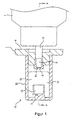
- Numeral 1 represents a push button.
- the push button 1 is connected to a stem 3 of a valve mechanism (not shown) disposed on an aerosol container 2, and is disposed that the stem 3 to be pressed when the user presses the flange 4 protruded outward to the circumference of the aerosol container 2.
- the push button 1 has an injection passage 5 therein connected to the stem 3 and a plurality of injection outlets 6 at the leading end portion. By a plurality of injection outlets 6 being disposed, the efficiency of the interfusion of a foamed aerosol content with air can be improved than injecting from one injection outlet 6, and efficiency of oxidization and foaming of the foamed aerosol content can be improved.
- a collision wall 7 for colliding the foamed aerosol content is disposed towards the injection outlets 6 and in a concave conical shape.
- the collision wall 7 is formed at a leading edge portion of a rectangular letter U shaped bridge member 10, which is connected to the push button 1 connected to the stem 3 of the aerosol container 2.
- at least a lower side of an injection axis line 11 of the foamed aerosol content foamed between the collision wall 7 and the injection outlets 6, is being correspondent to the lower side of an opening 12, wherein the openings 12 are disposed at the upper and lower side of the bridge member 10.
- the opening 12 formed at a lower side surface of the bridge member 10 is used as an outflowing outlet 14.
- a retention chamber 15 for temporary retaining the foamed aerosol content 13 in a foamed state is disposed at the injection outlets 6 side of the collision wall 7.
- the retention chamber 15 temporary retains the foamed aerosol content 13 foamed by injected from the injection outlets 6 and collided to the collision wall 7, thereby preventing the foamed aerosol content 13 to be shattered outward and attaining the foamed aerosol content 13 to be easily received by a human hand, a comb or a brush.
- aerosol injection nozzle above configured, when injecting the foamed aerosol content 13, in a state holding the aerosol container 2 by hand in a horizontal position, pressing the stem 3 of the valve mechanism (not shown) by putting a finger onto the flange 4 of the push button 1 and pressing the flange 4 towards the aerosol container 2.
- the stem 3 When the stem 3 is pressed, the aerosol container 2 and the injection outlets 6 are connected, and the foamed aerosol content 13 in the aerosol container 2 injects from a plurality of the injection outlets 6 via an injecting passage 5 of the push button 1
- the injection is jet injected from a plurality of the injection outlets 6, which are formed in a minute diameter. Also, by a flowing force occurred due to the jet injection, an ejecting phenomenon occurs and external air is introduced into the retention chamber 15 from the opening 12 of the bridge member 10.
- the foamed aerosol content 13 in the retention chamber 15 is outflowed from the outflowing outlet 14.
- the foamed aerosol content 13 efficiently foamed by interfusing with air is improved in adhering ability against the applying target, and therefore, the trickling of the content or shattering into the air is prevented and can be easily applied to the applying target.
- the conventional invention described in JP-A-8-229463 has a problem that a foamed aerosol and dust adhered to the minute openings of the mesh screen causes a clogging.
- the present invention there is no minute opening as those of the mesh screen formed onto the injection outlets 6, and the outflowing outlet 14 for the foamed aerosol content 13 has a large diameter. Therefore, even when some foamed aerosol content 13 or dust is adhered to the outflowing outlet 14, the clogging will not occur so that the injection of the foamed aerosol content can be repeated in a good condition.
- the outflowing outlet 14 is constituted as the opening 12 formed at a lower side surface of the bridge member 10, wherein at least a lower side of an injection axis line 11 of the foamed aerosol content foamed between the collision wall 7 and the injection outlets 6, is being correspondent to the lower side of an opening 12, wherein the openings 12 are disposed at the upper and lower side of the bridge member 10. Therefore, the outflowing outlet 14 of the foamed aerosol content 13 in a foamed state, can be largely formed, thereby even the foamed aerosol content 13 having a high viscosity can be assuredly outflowed without any occurrence of clogging.
- the aerosol injection nozzle forms a foaming by colliding the foamed aerosol content with the collision wall 7 and interfusing with air, so that there is no need to attach an additional member such as a mesh screen, and the aerosol injection nozzle having efficient foaming effect can be manufactured in a simple constitution and in low costs.
- the foamed aerosol content 13 when using a foamed aerosol content 13 that works by oxidizing such as an oxidizing hair dye, the foamed aerosol content 13 is efficiently oxidized by interfusing with air within the retention chamber 15, so that the effectiveness as an oxidizing hair dye can be improved.
- the quality of the foamed aerosol content 13 can be preserved, and can be used in a very efficacious state.
- the aerosol container 2 is held horizontally when injecting the foamed aerosol content 13.
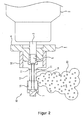
- An aerosol injection nozzle according to a second embodiment of the invention as shown in Fig. 4, the aerosol container 2 is held in an erected state when injecting the foamed aerosol content 13.
- a nozzle member 16 is disposed and protruded from one side of the push button 1 fixed to the stem 3.
- the injection outlets 6 of the nozzle member 16 is formed in a manner that enables the foamed aerosol content 13 to be jet injected by forming the injection passage 5 connected to the stem 3 long with a minute diameter.
- the injection outlets 6 has an interfusion portion 17 disposed toward the injection outlets 6 and formed in a cylinder shape, for interfusing the foamed aerosol content 13 and air and outflowing the interfused foamed aerosol content 13.
- a retention chamber 15 is disposed toward the injection outlets 6, for temporary retaining the foamed aerosol content 13, thereby the foamed aerosol content 13 can be injected within the retention chamber 15 from the injection outlets 6.
- the retention chamber 15 has a collision wall 7 for colliding the foamed aerosol content 13 in a concaved conical shape, which is formed by concaving the wall surface where the foamed aerosol content 13 is to be injected in a concaved conical shape.
- the nozzle member 16 has an air introducing inlets 18 for introducing exterior air into the retention chamber 15, and disposed at a side of the injection inlet 6 than the collision wall 7.
- Each of the air introducing inlets 18, as shown in Fig. 4, are formed at two of the upper portion of the interfusion portion 17, respectively, and introduce exterior air into the retention chamber 15.
- the foamed aerosol content 13 is injected by pressing the push button 1 downwards when the aerosol container 2 is held in an erected state.
- the pressing of the push button 1 opens the valve mechanism via the stem 3, and the foamed aerosol content 13 is injected from the injection outlets 6 and collides to the collision wall 7 to be foamed.
- the other functioning of the second embodiment is same with the aforementioned first embodiment.
- the collision wall 7 is formed in a concaved conical shape.
- the collision wall 7 is formed, as shown in Fig. 5, in a protruded conical shape in direction correspondent to the injection axis line 11 of the foamed aerosol content 13 injecting from the injection outlets 6.
- the foamed aerosol content 13 collided to the collision wall 7 rotates around the periphery of the protruded conical shape forming a vortex, and diffuses widely, thereby the time length retaining within the retention chamber 15 becomes long and efficient interfusion with air and improved foaming efficiency can be attained.
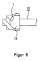
- the collision wall 7 is formed, as shown in Fig. 6, in a concaved C-lettered shape in direction correspondent to the injection axis line 11 of the foamed aerosol content injecting from the injection outlets 6.
- convection occurs within the concaved C-lettered shape to the foamed aerosol content 13 collided to the collision wall 7, thereby the time length retaining within the retention chamber 15 becomes long.
- the convection of the foamed aerosol content 13 collides to the following injected foamed aerosol content 13, thereby the efficient interfusion with air and improved foaming efficiency can be attained.
- the collision wall 7 when forming the collision wall 7 in a concaved C-lettered shape, it is possible to form only the collision wall 7 in a concaved C-lettered shape, but it is also possible to form the collision wall 7, as shown in Fig. 6, in a concaved C-lettered shape in a manner integrated with the retention chamber 15.
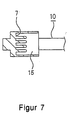
- the collision wall 7 is formed, as shown in Fig. 7, to have a plurality of protrusion at given intervals. According to the configuration, the foamed aerosol content 13 collided into the collision wall 7 collides to the following injected foamed aerosol content 13, thereby the time length retaining within the retention chamber 15 can be made longer and efficient interfusion with air and improved foaming efficiency can be attained.
- the bridge member 10 is formed in a rectangular letter U shape.
- the bridge member 10 In an L-lettered shape instead of the rectangular letter U shape, as of an aerosol injection nozzle according to a sixth embodiment of the invention.
- the shape of the bridge member 10 can be simplified and lower the cost of the product.
- the configuration lowers the mechanical strength of the bridge member 10 than that formed in a rectangular letter U shape.
- a plurality of the injection outlets 6 are disposed towards the collision wall 7, thereby the efficiency of the interfusion can be improved, but the manufacturing cost of a metal mold becomes expensive when forming a plurality of injection outlets 6.
- an aerosol injection nozzle according to a seventh embodiment has only one injection outlet 6, thereby reducing the manufacturing cost of a metal mold than that for a product having a plurality of injection outlets.
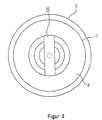
- the aerosol injection nozzle has a push button 1 connected to a stem 3 of a valve mechanism (not shown) disposed on an aerosol container 2, and is disposed that the stem 3 to be pressed when the user presses the stepped pressing portion 20 formed at the circumference of the push button 1.
- the push button 1 has an injection passage 5 therein connected to the stem 3 and a plurality of injection outlets 6 at the leading end portion.
- a ring shaped flow passage 21 for colliding the foamed aerosol content 13 is disposed towards the injection outlets 6.
- the injection axis line 11 of the foamed aerosol content 13 is disposed in direction tangent to the ring shaped flow passage 21.
- the foamed aerosol content 13 injected from the injection outlets 6 collides into the collision wall 7 disposed at an inner surface 23 of the ring shaped flow passage 21. Therefore, the foamed aerosol content 13 collided to the collision wall 7 disposed at the inner surface 23 of the ring shaped flow passage 21 interfuse with air due to the collision, thereby to be foamed by rotating at least for a 360-degree within the ring shaped flow passage 21.
- the foamed aerosol content 13 rotates for a plurality of times to be more interfused with air and to be foamed.
- the foamed aerosol content 13 in a foamed state rotates and collides to the following formed aerosol content 13 jet injected from the injection outlets 6 into the flow passage 21, and the interfusion with air becomes more efficient. Due to the foamed aerosol content 13 jet injected into the flow passage 21, air is introduced into the flow passage 21, and therefore, the flow passage 21 is filled with air. Therefore, the foamed aerosol content 13 can be assuredly foamed and the foaming and oxidizing thereof can be improved.
- the flow passage 21 is formed at a leading edge portion of a rectangular letter U shaped bridge member 10, which is connected to the push button 1 connected to the stem 3 of the aerosol container 2. And at least a lower side of an injection axis line 11 of the foamed aerosol content foamed between the flow passage 21 and the injection outlets 6, is being correspondent to the lower side of an opening 12, wherein the openings 12 are disposed at the upper and lower side of the bridge member 10.
- the opening 12 formed at a lower side surface of the bridge member 10 is used as an outflowing outlet 14 for the foamed aerosol content 13 in a foamed state.
- the conventional invention described in JP-A-8-229463 has a problem that a foamed aerosol and dust adhered to the minute openings of the mesh screen causes a clogging.
- the present invention there is no minute openings as those of the mesh screen formed onto the injection outlets 6, and the outflowing outlet 14 for the foamed aerosol content 13 has a large diameter. Therefore, even when some foamed aerosol content 13 or a dust is adhered to the outflowing outlet 14, the clogging will not occur so that the injection of the foamed aerosol content can be repeated in good condition.
- the outflowing outlet 14 is constituted as the opening 12 formed at a lower side surface of the bridge member 10, wherein at least a lower side of an injection axis line 11 of the foamed aerosol content foamed between the flow passage 21 and the injection outlets 6, is being correspondent to the lower side of an opening 12, wherein the openings 12 are disposed at the upper and lower side of the bridge member 10. Therefore, the outflowing outlet 14 of the foamed aerosol content 13 in a foamed state, can be largely formed, thereby even the foamed aerosol content 13 having a high viscosity can be assuredly outflowed without any occurrence of clogging.
- the aerosol injection nozzle forms a foaming by colliding the foamed aerosol content with the collision wall 7 at the inner surface 23 of the flow passage 21 and interfusing with air, so that there is no need to attach an additional member such as a mesh screen, and the aerosol injection nozzle having efficient foaming effect can be manufactured in a simple constitution and in low cost.
- the foamed aerosol content 13 when using a foamed aerosol content 13 that works by oxidizing such as an oxidizing hair dye, the foamed aerosol content 13 is efficiently oxidized by interfusing with air within the flow passage 21, so that the effectiveness as an oxidizing hair dye can be improved. Moreover, by not containing the foamed aerosol content 13 in the aerosol container 2 in a pre-oxidized state, and by oxidizing the foamed aerosol content 13 by interfusing with air within the flow passage 21 just before the use thereof, the quality of the foamed aerosol content 13 can be preserved, and can be used in a very efficacious state.
- the bridge member 10 is formed in a rectangular letter U shape.
- the shape of the bridge member 10 can be simplified and lower the cost of the product.
- the configuration lowers the mechanical strength of the bridge member 10 than that formed in a rectangular letter U shape.
- a plurality of the injection outlets 6 are disposed towards the flow passage 21, thereby the efficiency of the interfusion can be improved, but the manufacturing cost of a metal mold becomes expensive when forming a plurality of injection outlets 6.
- an aerosol injection nozzle according to a seventh embodiment has only one injection outlet 6, thereby reducing the manufacturing cost of a metal mold than that for a product having a plurality of injection outlets.
- hair foam as the example of the foamed aerosol content contained in the aforementioned aerosol container having the above described aerosol injection nozzle is shown below.
- Hair foam 95% alcohol 10.00 wt% methyl paraben 0.10 wt% reodol TW-0120 1.00 wt% silicon BY22-007 0.20 wt% xanthan gum 0.10 wt% vinyl acetete vinyl pyrrolidone copolymerization 1.00 wt% vinyl pyrrolidone -N,N- dimethylamido ethyl methacrylate copolymerization diethyl hydrosulfate 10.00 wt% purified water 77.6 wt% Total 100.00 wt%
- the above liquid concentrate is filled in an ordinary aluminum container can by pressurizing to 0.8 MPa with carbon dioxide gas.
- Skin-care foam 95% alcohol 5.00 wt% methyl paraben 0.10 wt% xanthan gum 0.10 wt% hydroxyethyl cellulose 0.05 wt% aminocoat 1.00 wt% 1.3-butylene glycol 3.00 wt% polyoxyethylene tridecylether 1.00 wt% purified water 89.75 wt% Total 100.00 wt%
- the above liquid concentrate is filled in internal bag of an double-layer aerosol container.
- the present invention is constituted as above, and therefore, it is possible to efficiently foam a foamed aerosol content, and to form an outflowing outlet of the foamed aerosol in a large diameter in contrast to an constitution that disposing the outflowing outlet in injecting direction or in the vicinity of the injection outlet, thereby preventing a clogging of the outflowing outlet even when a foamed aerosol content is used, and repeatedly able to inject the foamed aerosol content.
- the foamed aerosol jet injected from the injection outlet strongly collides to a collision wall of an inner surface of a flow passage and flows at high speed within the flow passage formed in ring shape, thereby improve the foaming of the foamed aerosol content.
Landscapes
- Chemical & Material Sciences (AREA)
- Dispersion Chemistry (AREA)
- Engineering & Computer Science (AREA)
- Mechanical Engineering (AREA)
- Containers And Packaging Bodies Having A Special Means To Remove Contents (AREA)
- Nozzles (AREA)
Abstract
Description
| Hair foam | |
| 95% alcohol | 10.00 wt% |
| methyl paraben | 0.10 wt% |
| reodol TW-0120 | 1.00 wt% |
| silicon BY22-007 | 0.20 wt% |
| xanthan gum | 0.10 wt% |
| vinyl acetete vinyl pyrrolidone copolymerization | 1.00 wt% |
| vinyl pyrrolidone -N,N- dimethylamido ethyl methacrylate copolymerization diethyl hydrosulfate | 10.00 wt% |
| purified water | 77.6 wt% |
| Total | 100.00 wt% |
| Skin-care foam | |
| 95% alcohol | 5.00 wt% |
| methyl paraben | 0.10 wt% |
| xanthan gum | 0.10 wt% |
| hydroxyethyl cellulose | 0.05 wt% |
| aminocoat | 1.00 wt% |
| 1.3-butylene glycol | 3.00 wt% |
| polyoxyethylene tridecylether | 1.00 wt% |
| purified water | 89.75 wt% |
| Total | 100.00 wt% |
Claims (13)
- An aerosol injection nozzle comprising: a collision wall to be collided and interfusing with air, disposed at an injection outlet for a foamed aerosol content; and an outflowing outlet for outflowing the foamed aerosol content foamed upon collision to the collision wall, connected to the collision wall and disposed at a lower side of the collision wall.
- An aerosol injection nozzle comprising: a retention chamber for temporary retaining foamed aerosol content in a foamed state; a collision wall for a foamed aerosol content to be collided and interfusing with air, disposed at an injection outlet for the foamed aerosol content and within the retention chamber; and outflowing outlet for outflowing the foamed aerosol content foamed by colliding to the collision wall, disposed at a lower side of the injection axis line between the retention chamber and the injection outlet.
- The aerosol injection nozzle according to any one of claims 1 and 2, wherein the collision wall is connected to a push button connected to a stem of an aerosol container via a bridge member having a rectangular letter U shape and having openings at upper and lower side surfaces, wherein the outflowing outlet is formed as an opening formed at a lower side surface of the bridge member.
- The aerosol injection nozzle according to any one of claims 1 and 2, wherein the collision wall is connected to a push button connected to a stem of an aerosol container via a bridge member having an L-lettered shape and having openings at upper and lower side surfaces, wherein the outflowing outlet is formed as an opening formed at a lower side surface of the bridge member.
- The aerosol injection nozzle according to any one of claims 1 and 2, wherein one or more of the injection outlets disposed towards the collision wall is formed.
- The aerosol injection nozzle according to any one of claims 1, 2, 3 or 4, wherein the collision wall is formed in a concaved conical shape in direction correspondent to the injection axis line of the foamed aerosol content injecting from the injection outlet.
- The aerosol injection nozzle according to any one of claims 1, 2, 3 or 4, wherein the collision wall is formed in a protruded conical shape in direction correspondent to the injection axis line of the foamed aerosol content injecting from the injection outlet.
- The aerosol injection nozzle according to any one of claims 1, 2, 3 or 4, wherein the collision wall is formed in a concaved C-lettered shape in direction correspondent to the injection axis line of the foamed aerosol content injecting from the injection outlet.
- The aerosol injection nozzle according to any one of claims 1, 2, 3 or 4, wherein the collision wall is formed to have a plurality of protrusions at given intervals.
- An aerosol injection nozzle comprising: a ring shaped flow passage for foamed aerosol content to be collided and interfusing with air, disposed at an injection outlet; and an injection axis line of the foamed aerosol content, disposed in direction tangent to the ring shaped flow passage, wherein colliding the foamed aerosol content injected from the injection outlet into a collision wall inside the ring shaped flow passage and interfusing the foamed aerosol content with air to be foamed by rotating at least for a 360-degree within the ring shaped flow passage, wherein outflowing the foamed aerosol content foamed from an outflowing outlet disposed at lower surface of the ring shaped flow passage.
- The aerosol injection nozzle according to claim 10, wherein the ring shaped flow passage is connected to a push button connected to a stem of an aerosol container via a bridge member having a rectangular letter U shape and having openings at upper and lower side surfaces, wherein the outflowing outlet is formed as an opening formed at a lower side surface of the bridge member.
- The aerosol injection nozzle according to claim 10, wherein the ring shaped flow passage is connected to a push button connected to a stem of an aerosol container via a bridge member having an L-lettered shape and having openings at upper and lower side surfaces, wherein the outflowing outlet is formed as an opening formed at a lower side surface of the bridge member.
- The aerosol injection nozzle according to claim 10, wherein one or more of the injection outlet disposed towards the collision wall is formed.
Applications Claiming Priority (5)
| Application Number | Priority Date | Filing Date | Title |
|---|---|---|---|
| JP2001318627A JP3896270B2 (en) | 2001-10-16 | 2001-10-16 | Aerosol spray nozzle |
| JP2001318627 | 2001-10-16 | ||
| JP2002267204 | 2002-09-12 | ||
| JP2002267204A JP3966546B2 (en) | 2002-09-12 | 2002-09-12 | Aerosol spray nozzle |
| PCT/JP2002/010672 WO2003033166A1 (en) | 2001-10-16 | 2002-10-15 | Aerosol spray nozzle |
Publications (3)
| Publication Number | Publication Date |
|---|---|
| EP1439005A1 true EP1439005A1 (en) | 2004-07-21 |
| EP1439005A4 EP1439005A4 (en) | 2007-04-18 |
| EP1439005B1 EP1439005B1 (en) | 2009-03-11 |
Family
ID=26623933
Family Applications (1)
| Application Number | Title | Priority Date | Filing Date |
|---|---|---|---|
| EP02775354A Expired - Lifetime EP1439005B1 (en) | 2001-10-16 | 2002-10-15 | Aerosol spray nozzle |
Country Status (4)
| Country | Link |
|---|---|
| US (1) | US7059546B2 (en) |
| EP (1) | EP1439005B1 (en) |
| DE (1) | DE60231527D1 (en) |
| WO (1) | WO2003033166A1 (en) |
Families Citing this family (22)
| Publication number | Priority date | Publication date | Assignee | Title |
|---|---|---|---|---|
| US7278590B1 (en) | 1992-02-24 | 2007-10-09 | Homax Products, Inc. | Systems and methods for applying texture material to ceiling surfaces |
| EP1342465B1 (en) * | 2002-03-05 | 2011-10-19 | Kao Corporation | Foam-type hair dye and foam-type hair dye discharge container |
| GB0323908D0 (en) * | 2003-10-11 | 2003-11-12 | Nupharm Lab Ltd | Pharmaceutical foam formulation |
| US7677420B1 (en) | 2004-07-02 | 2010-03-16 | Homax Products, Inc. | Aerosol spray texture apparatus for a particulate containing material |
| US7487893B1 (en) | 2004-10-08 | 2009-02-10 | Homax Products, Inc. | Aerosol systems and methods for dispensing texture material |
| US8344056B1 (en) | 2007-04-04 | 2013-01-01 | Homax Products, Inc. | Aerosol dispensing systems, methods, and compositions for repairing interior structure surfaces |
| US8580349B1 (en) | 2007-04-05 | 2013-11-12 | Homax Products, Inc. | Pigmented spray texture material compositions, systems, and methods |
| US9382060B1 (en) | 2007-04-05 | 2016-07-05 | Homax Products, Inc. | Spray texture material compositions, systems, and methods with accelerated dry times |
| WO2011016011A2 (en) | 2009-08-07 | 2011-02-10 | Ecolab Usa Inc. | Wipe and seal product pump |
| US20130193233A1 (en) * | 2010-10-05 | 2013-08-01 | Meadwestvaco Calmar, Inc. | Foaming aerosol actuator and methods of making the same |
| US20120312895A1 (en) * | 2011-06-09 | 2012-12-13 | S.C. Johnson & Son, Inc. | Fluid Dispensing Device for Discharging Fluid Simultaneously in Multiple Directions |
| US9156042B2 (en) | 2011-07-29 | 2015-10-13 | Homax Products, Inc. | Systems and methods for dispensing texture material using dual flow adjustment |
| US9248457B2 (en) | 2011-07-29 | 2016-02-02 | Homax Products, Inc. | Systems and methods for dispensing texture material using dual flow adjustment |
| US9156602B1 (en) | 2012-05-17 | 2015-10-13 | Homax Products, Inc. | Actuators for dispensers for texture material |
| HUE042993T2 (en) * | 2013-02-07 | 2019-07-29 | Weener Plastics Netherlands B V | Actuator and dispensing apparatus |
| US9435120B2 (en) | 2013-03-13 | 2016-09-06 | Homax Products, Inc. | Acoustic ceiling popcorn texture materials, systems, and methods |
| CA2859537C (en) | 2013-08-19 | 2019-10-29 | Homax Products, Inc. | Ceiling texture materials, systems, and methods |
| USD787326S1 (en) | 2014-12-09 | 2017-05-23 | Ppg Architectural Finishes, Inc. | Cap with actuator |
| CN111902220A (en) * | 2018-04-06 | 2020-11-06 | 东洋喷雾工业株式会社 | Spray product |
| US11806560B1 (en) * | 2018-05-01 | 2023-11-07 | Amazon Technologies, Inc. | Fire suppression nozzle and system for stackable inventory storage modules |
| DE102021124355B4 (en) | 2021-09-21 | 2023-05-04 | Jürgen F. Vorwerk | Rotating injector nozzle and its use as well as device for CIP cleaning and CIP processes |
| CN117298495B (en) * | 2023-09-04 | 2026-02-03 | 广东汇杰电力集团有限公司 | Automatic fire control shower nozzle |
Family Cites Families (8)
| Publication number | Priority date | Publication date | Assignee | Title |
|---|---|---|---|---|
| DE3066837D1 (en) * | 1979-08-16 | 1984-04-12 | Canyon Corp | Foam dispenser |
| ES2013068A6 (en) * | 1989-03-06 | 1990-04-16 | Monturas Sa | A foaming device |
| JPH0616687B2 (en) | 1990-06-21 | 1994-03-09 | ホーユー株式会社 | Low calorie food and drink |
| JP2531560Y2 (en) * | 1990-09-07 | 1997-04-02 | 株式会社丸一製作所 | spray nozzle |
| JP3566368B2 (en) * | 1994-12-09 | 2004-09-15 | 株式会社吉野工業所 | Spring member of trigger sprayer |
| US5611490A (en) * | 1994-12-19 | 1997-03-18 | Calmar Inc. | Foamer assembly for fluid dispenser |
| US6036112A (en) * | 1998-04-17 | 2000-03-14 | Continental Sprayers International, Inc. | Foaming nozzle for trigger sprayer |
| JP2002066388A (en) | 2000-08-29 | 2002-03-05 | Toyo Aerosol Ind Co Ltd | Jetting nozzle for aerosol |
-
2002
- 2002-10-15 WO PCT/JP2002/010672 patent/WO2003033166A1/en not_active Ceased
- 2002-10-15 DE DE60231527T patent/DE60231527D1/en not_active Expired - Lifetime
- 2002-10-15 EP EP02775354A patent/EP1439005B1/en not_active Expired - Lifetime
- 2002-10-15 US US10/450,328 patent/US7059546B2/en not_active Expired - Fee Related
Also Published As
| Publication number | Publication date |
|---|---|
| US20040050956A1 (en) | 2004-03-18 |
| WO2003033166A1 (en) | 2003-04-24 |
| DE60231527D1 (en) | 2009-04-23 |
| US7059546B2 (en) | 2006-06-13 |
| EP1439005B1 (en) | 2009-03-11 |
| EP1439005A4 (en) | 2007-04-18 |
Similar Documents
| Publication | Publication Date | Title |
|---|---|---|
| US7059546B2 (en) | Aerosol spray nozzle | |
| JP3865485B2 (en) | Flow control device for aerosol containers | |
| JP2968944B2 (en) | Valve device for aerosol container | |
| AU693524B2 (en) | Discharge device for free-flowing liquids, in particular for discharge in only one stroke | |
| EP0526473A4 (en) | ||
| IE49761B1 (en) | Non-pressurized dispensing system | |
| JP2000072657A (en) | Post-foamable shower gel | |
| US7048153B2 (en) | Foam dispensing article | |
| KR20100054128A (en) | Venturi effect spraying device and its use in cosmetology and perfumery | |
| JP2002066388A (en) | Jetting nozzle for aerosol | |
| JP2000153188A (en) | Push button for compressed gas aerosol | |
| JPH0541798Y2 (en) | ||
| JP4121656B2 (en) | Aerosol products | |
| JP3896270B2 (en) | Aerosol spray nozzle | |
| JP3966546B2 (en) | Aerosol spray nozzle | |
| JPH10236554A (en) | Double aerosol container | |
| JP4546134B2 (en) | Liquid application container | |
| JP4960769B2 (en) | Aero pushbutton | |
| JP4561952B2 (en) | Water discharge device | |
| JPH1024258A (en) | Container cosmetics | |
| JP4057381B2 (en) | Spray container | |
| JPH11105953A (en) | Aerosol container | |
| JP4285813B2 (en) | Valve device for aerosol container | |
| JP2000281157A (en) | Push button for aerosol container | |
| JP3895428B2 (en) | Quantitative injection device for aerosol containers |
Legal Events
| Date | Code | Title | Description |
|---|---|---|---|
| PUAI | Public reference made under article 153(3) epc to a published international application that has entered the european phase |
Free format text: ORIGINAL CODE: 0009012 |
|
| 17P | Request for examination filed |
Effective date: 20040517 |
|
| AK | Designated contracting states |
Kind code of ref document: A1 Designated state(s): AT BE BG CH CY CZ DE DK EE ES FI FR GB GR IE IT LI LU MC NL PT SE SK TR |
|
| A4 | Supplementary search report drawn up and despatched |
Effective date: 20070315 |
|
| 17Q | First examination report despatched |
Effective date: 20070608 |
|
| GRAP | Despatch of communication of intention to grant a patent |
Free format text: ORIGINAL CODE: EPIDOSNIGR1 |
|
| GRAS | Grant fee paid |
Free format text: ORIGINAL CODE: EPIDOSNIGR3 |
|
| GRAA | (expected) grant |
Free format text: ORIGINAL CODE: 0009210 |
|
| AK | Designated contracting states |
Kind code of ref document: B1 Designated state(s): CH DE FR GB IT LI |
|
| REG | Reference to a national code |
Ref country code: GB Ref legal event code: FG4D |
|
| REG | Reference to a national code |
Ref country code: CH Ref legal event code: EP |
|
| REF | Corresponds to: |
Ref document number: 60231527 Country of ref document: DE Date of ref document: 20090423 Kind code of ref document: P |
|
| REG | Reference to a national code |
Ref country code: CH Ref legal event code: NV Representative=s name: KATZAROV S.A. |
|
| PLBE | No opposition filed within time limit |
Free format text: ORIGINAL CODE: 0009261 |
|
| STAA | Information on the status of an ep patent application or granted ep patent |
Free format text: STATUS: NO OPPOSITION FILED WITHIN TIME LIMIT |
|
| 26N | No opposition filed |
Effective date: 20091214 |
|
| PGFP | Annual fee paid to national office [announced via postgrant information from national office to epo] |
Ref country code: DE Payment date: 20101022 Year of fee payment: 9 |
|
| PGFP | Annual fee paid to national office [announced via postgrant information from national office to epo] |
Ref country code: GB Payment date: 20101021 Year of fee payment: 9 Ref country code: IT Payment date: 20101025 Year of fee payment: 9 |
|
| PGFP | Annual fee paid to national office [announced via postgrant information from national office to epo] |
Ref country code: FR Payment date: 20111103 Year of fee payment: 10 Ref country code: CH Payment date: 20111024 Year of fee payment: 10 |
|
| REG | Reference to a national code |
Ref country code: CH Ref legal event code: PL |
|
| GBPC | Gb: european patent ceased through non-payment of renewal fee |
Effective date: 20121015 |
|
| REG | Reference to a national code |
Ref country code: FR Ref legal event code: ST Effective date: 20130628 |
|
| PG25 | Lapsed in a contracting state [announced via postgrant information from national office to epo] |
Ref country code: GB Free format text: LAPSE BECAUSE OF NON-PAYMENT OF DUE FEES Effective date: 20121015 Ref country code: CH Free format text: LAPSE BECAUSE OF NON-PAYMENT OF DUE FEES Effective date: 20121031 Ref country code: LI Free format text: LAPSE BECAUSE OF NON-PAYMENT OF DUE FEES Effective date: 20121031 Ref country code: DE Free format text: LAPSE BECAUSE OF NON-PAYMENT OF DUE FEES Effective date: 20130501 |
|
| REG | Reference to a national code |
Ref country code: DE Ref legal event code: R119 Ref document number: 60231527 Country of ref document: DE Effective date: 20130501 |
|
| PG25 | Lapsed in a contracting state [announced via postgrant information from national office to epo] |
Ref country code: FR Free format text: LAPSE BECAUSE OF NON-PAYMENT OF DUE FEES Effective date: 20121031 Ref country code: IT Free format text: LAPSE BECAUSE OF NON-PAYMENT OF DUE FEES Effective date: 20121015 |