EP1437813A2 - Apparatus for and method of ground fault detection - Google Patents
Apparatus for and method of ground fault detection Download PDFInfo
- Publication number
- EP1437813A2 EP1437813A2 EP04250050A EP04250050A EP1437813A2 EP 1437813 A2 EP1437813 A2 EP 1437813A2 EP 04250050 A EP04250050 A EP 04250050A EP 04250050 A EP04250050 A EP 04250050A EP 1437813 A2 EP1437813 A2 EP 1437813A2
- Authority
- EP
- European Patent Office
- Prior art keywords
- current
- ground fault
- protection system
- generator
- fault protection
- Prior art date
- Legal status (The legal status is an assumption and is not a legal conclusion. Google has not performed a legal analysis and makes no representation as to the accuracy of the status listed.)
- Granted
Links
Images


Classifications
-
- H—ELECTRICITY
- H02—GENERATION; CONVERSION OR DISTRIBUTION OF ELECTRIC POWER
- H02H—EMERGENCY PROTECTIVE CIRCUIT ARRANGEMENTS
- H02H3/00—Emergency protective circuit arrangements for automatic disconnection directly responsive to an undesired change from normal electric working condition with or without subsequent reconnection ; integrated protection
- H02H3/26—Emergency protective circuit arrangements for automatic disconnection directly responsive to an undesired change from normal electric working condition with or without subsequent reconnection ; integrated protection responsive to difference between voltages or between currents; responsive to phase angle between voltages or between currents
- H02H3/28—Emergency protective circuit arrangements for automatic disconnection directly responsive to an undesired change from normal electric working condition with or without subsequent reconnection ; integrated protection responsive to difference between voltages or between currents; responsive to phase angle between voltages or between currents involving comparison of the voltage or current values at two spaced portions of a single system, e.g. at opposite ends of one line, at input and output of apparatus
-
- H—ELECTRICITY
- H02—GENERATION; CONVERSION OR DISTRIBUTION OF ELECTRIC POWER
- H02H—EMERGENCY PROTECTIVE CIRCUIT ARRANGEMENTS
- H02H3/00—Emergency protective circuit arrangements for automatic disconnection directly responsive to an undesired change from normal electric working condition with or without subsequent reconnection ; integrated protection
- H02H3/006—Calibration or setting of parameters
-
- H—ELECTRICITY
- H02—GENERATION; CONVERSION OR DISTRIBUTION OF ELECTRIC POWER
- H02H—EMERGENCY PROTECTIVE CIRCUIT ARRANGEMENTS
- H02H7/00—Emergency protective circuit arrangements specially adapted for specific types of electric machines or apparatus or for sectionalised protection of cable or line systems, and effecting automatic switching in the event of an undesired change from normal working conditions
- H02H7/06—Emergency protective circuit arrangements specially adapted for specific types of electric machines or apparatus or for sectionalised protection of cable or line systems, and effecting automatic switching in the event of an undesired change from normal working conditions for dynamo-electric generators; for synchronous capacitors
Definitions
- the present invention relates to an apparatus for and method of ground fault detection.
- a ground fault which is the presence of an unwanted current path from a supply to ground, can be determined by detecting a difference between the current supplied from a power supply, such as a generator, and the current supplied to a load.
- Conventional methods for providing ground fault detection include monitoring the generator current and the load current with two shunts, with two current transformers or two hall effect devices each of which must be matched to one another so as to provide accurate detections. Even if the components are accurately matched, which generally requires the use of high cost sensing elements, imprecision may still occur due to thermal differences between the sensing elements thereby resulting in them becoming mismatched again. This may then lead to an indication of a ground fault by virtue of an apparent difference between the current supplied from the generator and the current supplied to the load even when no such difference exists.
- US 5,539,602 discloses a ground fault interrupter in which a first resistor R1 is used to measure the current flowing to a load and a second resistor R2 is used to measure the current flowing from the load.
- R1 and R2 are equal, so forming the difference between the voltage drops across the resistors should result in a zero value in the absence of a ground fault. The presence of a ground fault is indicated by the difference value exceeding a threshold.
- the resistors R1 and R2 can be different. In which case a specific non-zero value in the difference between the voltage drops is taken to be indicative that a ground fault does not exist.
- a ground fault protection system comprising a first current measuring device for measuring current flow to a load; a second current measuring device for measuring current flow from a source of electrical power; and a controller arranged to compare current measurements from the first and second current measuring devices when there is no ground fault condition, to derive a relationship between the measurements and on the basis of the relationship to compare the current flow to the load and the current flow from the source of electrical power and to disconnect or de-energise the source of electrical power if the currents differ by more than a predetermined value.
- the calibration can be arbitrary in that the controller merely seeks to obtain a usable correlation between the two current measuring devices and only one of the sensors needs to be accurate in order to obtain an accurate difference.
- the creation of a relationship between the responses of the first and second current measuring devices allows the respective outputs of the current measuring devices to be compared in a meaningful way even when the current drawn by the load changes. More specifically if a measurement of the responses of the current measuring devices is made when a first current is flowing, then the relationship allows the currents flowing through the measuring devices to be meaningfully compared when a second current, which may be significantly different from the first current, is flowing. Therefore this protection system can cope with changes in the load current flowing through the load.
- the correlation or correction between the two current measurements can be performed by scaling one of the measurements with respect to the other such that they match. This is especially likely to work if the current measurements are made by monitoring the voltage dropped across an ohmic element as result of current flow therein.
- the resistance of the or each ohmic element used for current measurement may vary and hence it may be necessary to calculate a revised resistance for the ohmic element, either continuously or on a periodic basis for use in the comparison of current flow.
- a revised resistance for the ohmic element either continuously or on a periodic basis for use in the comparison of current flow.
- the sensors need not merely be ohmic sensors, but other devices such as hall effect devices or current transformers can be used, and indeed mixed combinations of devices could be used such as the current shunt and a hall effect device provided that each device is reasonably well characterised such that a reasonable correlation between the currents as measured by each device can initially be established under no fault conditions.
- the controller can then determine a calibration correction which can be applied to the devices and updated from time to time.
- a method of detecting a ground fault comprising the steps of measuring the first current supplied to a load, measuring a second current supplied from a generator, and on the assumption that no ground fault condition exists applying a correction, scaling or mapping function to the measurements so as to substantially equate the measurements, and then to compare subsequent measurements of the first and second currents and to indicate a fault condition if a difference between these measurements exceeds a predetermined value.
- the correction, scaling or mapping function is updated with the passage of time.
- the correction value varies only slowly or in accordance with the time constant such that erroneous measurements, or measurements made in the presence of a ground fault condition do not perturb the method or apparatus before it is has the opportunity to signal that a fault condition exists.
- One of the current sensors may be a winding of a generator.
- FIG. 1 A typical starter generator system of the type found on aircraft is shown in Figure 1.
- the generator 2 has a rotating armature 4 which is energised by a current flowing through a field winding 6 from a controller (not shown).
- the generator also includes an interpole winding 8 (also known as a compensating winding) whose purpose is to compensate for the change in phase that would otherwise occur between the magnetic flux and the generated current as the generator current increases.
- the provision of the interpole winding helps minimise the voltage induced into the conductors between the main poles. By minimising this voltage difference sparking and arcing within the generator is reduced and this results in improved commutation and lower brush temperatures.
- the entirety of the generator current I g flows through the winding 8 and furthermore the generator is configured such that either end of the winding is accessible.
- the current flow through the winding 8 will give rise to a voltage drop across the winding which is proportional to the generator current I g .
- the resistance R a of the winding 8 will vary with the temperature of the winding and hence the resistance of the winding needs to be known at a given temperature before an accurate determination of the current flow therein can be made.
- An output 10 of generator 2 is connected to a load 12.
- a current shunt 14 is provided in the path to the load such that the load current I L can be determined.
- the contactor 18 which switches the generator load may be 30 feet from the generator 10. Ground faults in the cable 16 between the generator 10 and the contactor 18 may cause shorts which could damage the airframe and/or the generator.
- the generator current should equal the load current under all conditions. Any difference in current (Idif.) between the generator current, and the load current as sensed by current sensor 14, is indicative of a ground fault in cabling 16.
- the voltage V s occurring across the current shunt 14 is measured by a differential amplifier 20 at a time when there is assumed to be no ground fault.
- the output of the amplifier 20 is a function of current I L plus any noise occurring in the system at that time.
- the function is normally a simple scaling factor although other more complex functions may be provided for.
- the voltage V a occurring across the generator interpole winding 8 is also measured at this time.
- This voltage is measured by a differential amplifier 22 and the output of the amplifier is a function of the generator current together with any noise that is present in the system.
- the outputs from the amplifiers 20 and 22 may advantageously be filtered by filters 24 and 26, respectively.
- the filter 24 and 26 may serve to remove high frequency noise, and may also serve to average out the voltage and the current measurements so that they become representative of the current flowing over a period of time rather than an instantaneous current measurement.
- the filters are substantially matched so as not to introduce any substantial phase error which may give rise to false detections.
- a filtered variables V A and I G effectively provide a memory of the coil resistance R A . These filtered values can then be used to deduce the coil resistance R A and hence, from the voltage drop across it, determine the generator current I G .
- the measurements of I G and I L can then be compared periodically (separated by time periods which are shorter than the time constant of the filter).
- the action of such a system is that the measurement of the ground fault current will under no-fault conditions tend towards zero but any sudden change in the measured values of the generator current and the load current will result in the generation of a decaying estimate of the ground fault current.
- the decision time to trip the generator off is much shorter than the decay constant of the estimate of ground fault current then this system provides a reliable self-calibrating way of detecting ground fault current without requiring expensive matched sensors.
- the ground fault detector monitors the difference between the load current as measured by the shunt 14 and the voltage drop measured across the coil 8.
- Figure 2 shows an example in which the load current and the generator current are, at time zero, matched at 50 amps each.
- a ground fault is introduced such that a ground fault current of 100 amps flows in addition to the load current of 50 amps.
- the total current rises to 150 amps.
- the ground fault detector using the historical measurements of R A immediately sees the 100 amp difference between the currents, as shown in greater detail in Figure 3, and if this difference persists for more than a predetermined period, for example 50 ms, the ground fault detector issues a signal to trip the generator offline. However, if the generator is not tripped then the ground fault detector will seek to effectively recalibrate its value for R A such that the ground fault current I dif is returned to zero in accordance with a time period determined by the filters implemented within the ground fault detector. Thus, the detector 30 is only sensitive to changes in ground fault current rather than to the magnitude of the ground fault itself. Thus, as shown in Figure 3, at time 3 seconds the detector shows the ground fault current as zero even though in reality a 100 amp ground fault current exists.
- a further advantage of the system described lies in providing a ground fault detection system in which one of the current sensors is a winding of the generator. Such a system is cheaper to implement and lighter in weight than a conventional system using two independent current sensors.
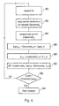
- FIG. 4 illustrates a flow chart for the implementation of the ground fault detector within a programmable digital computer.
- Control commences at step 60 where a measurement of I L is made.
- Control then passes to step 62 where a measurement is made of the voltage V A .
- control passes to step 66 where the new estimate R ANEW of the coil resistance is used to update a pre-existing estimate R A of the coil resistance this is performed by adding the difference between the old and new estimates of the coil resistance, multiplied by a factor D which is less than unity to the pre-existing estimate of the coil resistance. This has the effect that each time the step is executed the coil resistance is modified slightly and in response to a step change would asymptote/decay towards a new value.
- control is passed to step 68 where the generator current is calculated from I G is V A / R A .
- Control passes to step 70 where the modulus of the difference between the generator and load current is compared with the threshold TH1. If the difference is less than the threshold then control returns to step 60 whereas if the difference is more than the threshold then control passes to step 72 which causes the generator to be tripped offline.
- the first current measuring device is used to estimate the load current I L at a first time instant, and that this value is then used in the calculation of the impedence of the second current measuring device, and that this assumed impedence can then be used in conjunction with the measurement of voltage across the second current measuring device to estimate the current flowing through it.
- Figure 5 shows a further flow chart for implementing a further embodiment of the present invention. This further embodiment avoids the use of a division operator and hence places less demand upon a data processor.
- step 80 the voltage Va across the winding 8 is measured.
- the generator current "Gencurrent K” for the Kth measurement is determined at step 82 by applying a scaling factor to the measurement of Va.
- Control is then passed to step 84 where the load current "Loadcurrent K "is measured (for example by measuring the voltage across a shunt or by using some other current sensor).
- Igen K+1 Gencurrent K . a + Igen K .b
- step 86 control is passed to step 88 where a similar process is performed to estimate the load current IL K+1 for the next measurement/comparison cycle.
- control is passed to step 92 where the magnitude of diff is compared with the magnitude of a threshold value multiplied by Igen K , and if diff is bigger than the threshold value multiplied by Igen K , then control is passed to step 94 where a signal is asserted to open a contactor to take the generator off line, otherwise control is returned to step 80. The cycle is repeated with the next set of measurements.
Landscapes
- Engineering & Computer Science (AREA)
- Power Engineering (AREA)
- Testing Of Short-Circuits, Discontinuities, Leakage, Or Incorrect Line Connections (AREA)
- Control Of Eletrric Generators (AREA)
- Locating Faults (AREA)
Abstract
Description
Claims (15)
- A ground fault protection system, comprising:characterised by a controller (30) arranged to compare measurements from the first and second current measuring devices when there is no ground fault condition; to derive a relationship between the measurements; and on the basis of the relationship to compare the current flow to the load and the current flow from the source of electrical power and to disconnect or de-energise the source of electrical power if the currents differ by more than a predetermined value.a first current measuring device (14) for measuring current flow to a load;a second current measuring device (8) for measuring current flow from a source of electrical power (4);
- A ground fault detection system as claimed in claim 1, characterised in that the first current measuring device (14) is used to calibrate the second measuring device (8).
- A ground fault protection system as claimed in claim 1 or 2, characterised in that the source of electrical power is a generator (4) and the second current measuring device is a winding (8) within the generator.
- A ground fault protection system as claimed in claim 3, characterised in that the winding (8) within the generator is an interpole winding.
- A ground fault protection system as claimed in claim 3 or 4 characterised in that the controller (30) estimates the resistance of the winding (8).
- A ground fault protection system as claimed in claim 3, 4 or 5, characterised in that the controller measures the voltage (Va) occurring across the winding (8).
- A ground fault protection system as claimed in any one of the preceding claims, characterised in that the outputs of the first and second current measuring devices are filtered.
- A ground fault protection system as claimed in any one of the preceding claims, characterised in that the controller (30) applies a time varying correction to a measurement of current difference such that under no fault conditions the measurement of current difference tends to approach a reference value.
- A ground fault protection system as claimed in claim 8, characterised in that a ground fault is indicated when the measurement of current difference differs from the reference value by more than a first threshold.
- A ground fault protection system as claimed in claim 1, characterised in that the relationship derived when a first current is flowing allows the current measuring devices to be used to compare current flow at values different to the first current.
- A ground fault protection system as claimed in claim 1, characterised in that the first and second current measuring devices have dissimilar impedances.
- An aircraft including a ground fault protection system as claimed in any one of the preceding claims.
- A method of providing ground fault protection, comprising the steps of:measuring a first current supplied to a load;measuring a second current supplied from a generator;on the assumption that no ground fault condition exists, applying a correction, scaling or mapping function to the measurements so as to substantially equate the measurements, and then to compare the measurements of the first and second currents and to indicate a fault condition if the difference exceeds a predetermined value.
- A method as claimed in claim 13, in which the correction, scaling or mapping varies as a function of time so as to maintain the current measurements in substantial equally.
- A method as claimed in claim 14 in which the variation has a time constant such that short term difference are detectable as a fault condition.
Applications Claiming Priority (2)
| Application Number | Priority Date | Filing Date | Title |
|---|---|---|---|
| GB0300507 | 2003-01-09 | ||
| GBGB0300507.1A GB0300507D0 (en) | 2003-01-09 | 2003-01-09 | Apparatus for and method of ground fault detection |
Publications (3)
| Publication Number | Publication Date |
|---|---|
| EP1437813A2 true EP1437813A2 (en) | 2004-07-14 |
| EP1437813A3 EP1437813A3 (en) | 2006-06-21 |
| EP1437813B1 EP1437813B1 (en) | 2010-12-01 |
Family
ID=9950900
Family Applications (1)
| Application Number | Title | Priority Date | Filing Date |
|---|---|---|---|
| EP04250050A Expired - Lifetime EP1437813B1 (en) | 2003-01-09 | 2004-01-07 | Apparatus for and method of ground fault detection |
Country Status (5)
| Country | Link |
|---|---|
| US (1) | US7233464B2 (en) |
| EP (1) | EP1437813B1 (en) |
| DE (1) | DE602004030290D1 (en) |
| ES (1) | ES2357107T3 (en) |
| GB (1) | GB0300507D0 (en) |
Cited By (3)
| Publication number | Priority date | Publication date | Assignee | Title |
|---|---|---|---|---|
| CN108631263A (en) * | 2017-03-21 | 2018-10-09 | 上海复旦微电子集团股份有限公司 | Ground-fault protection system |
| FR3084311A1 (en) * | 2018-07-25 | 2020-01-31 | Robert Bosch Gmbh | Balancing method of a measuring installation equipping a motor vehicle |
| US10923899B2 (en) | 2017-03-21 | 2021-02-16 | Shanghai Fudan Microelectronics Group Company Limited | Ground fault protection system |
Families Citing this family (7)
| Publication number | Priority date | Publication date | Assignee | Title |
|---|---|---|---|---|
| ES2431138T3 (en) * | 2006-08-18 | 2013-11-25 | Abb Research Ltd | Grounding fault detection |
| US20080174922A1 (en) * | 2007-01-19 | 2008-07-24 | Tellabs Bedford, Inc. | Method and apparatus for detecting ground fault current on a power line |
| US8072225B2 (en) * | 2008-10-08 | 2011-12-06 | Hamilton Sundstrand Corporation | Differential power detection |
| US9662987B2 (en) * | 2011-02-18 | 2017-05-30 | Lear Corporation | Method and apparatus for detecting the existence of a safety ground |
| ES2676067T3 (en) * | 2015-08-05 | 2018-07-16 | Abb S.P.A. | A procedure to detect ground faults in an LVDC power line and an electronic device for it |
| CA3080229A1 (en) * | 2017-11-01 | 2019-05-09 | General Technologies Corp. | Valve-diagnostic system and device |
| CN118545110B (en) * | 2024-05-16 | 2025-09-19 | 中车青岛四方机车车辆股份有限公司 | Abnormality processing method for train grounding carbon brush, shaft temperature detecting system and train |
Family Cites Families (9)
| Publication number | Priority date | Publication date | Assignee | Title |
|---|---|---|---|---|
| US4550360A (en) * | 1984-05-21 | 1985-10-29 | General Electric Company | Circuit breaker static trip unit having automatic circuit trimming |
| US4703389A (en) * | 1986-04-10 | 1987-10-27 | General Electric Company | Static trip circuit breaker with automatic circuit trimming |
| US6188203B1 (en) * | 1996-11-01 | 2001-02-13 | Lucas Aerospace Power Equipment Corporation | Ground fault detection circuit |
| JP3468817B2 (en) * | 1994-02-25 | 2003-11-17 | 株式会社東芝 | Field ground fault detector |
| US5963457A (en) * | 1994-03-18 | 1999-10-05 | Hitachi, Ltd. | Electrical power distribution monitoring system and method |
| US5539602A (en) * | 1994-10-19 | 1996-07-23 | Gte Airfone Incorporated | Ground fault interrupter |
| JP2001018808A (en) | 1999-07-08 | 2001-01-23 | Tokai Rika Co Ltd | Grain-toned member and manufacture thereof |
| DE19959777A1 (en) * | 1999-12-07 | 2001-06-28 | Siemens Ag | Differential protection method |
| US6794883B2 (en) * | 2002-03-19 | 2004-09-21 | Emerson Electric Co. | Method and system for monitoring winding insulation resistance |
-
2003
- 2003-01-09 GB GBGB0300507.1A patent/GB0300507D0/en not_active Ceased
-
2004
- 2004-01-07 EP EP04250050A patent/EP1437813B1/en not_active Expired - Lifetime
- 2004-01-07 DE DE602004030290T patent/DE602004030290D1/en not_active Expired - Lifetime
- 2004-01-07 ES ES04250050T patent/ES2357107T3/en not_active Expired - Lifetime
- 2004-01-09 US US10/753,562 patent/US7233464B2/en not_active Expired - Lifetime
Cited By (4)
| Publication number | Priority date | Publication date | Assignee | Title |
|---|---|---|---|---|
| CN108631263A (en) * | 2017-03-21 | 2018-10-09 | 上海复旦微电子集团股份有限公司 | Ground-fault protection system |
| US10923899B2 (en) | 2017-03-21 | 2021-02-16 | Shanghai Fudan Microelectronics Group Company Limited | Ground fault protection system |
| FR3084311A1 (en) * | 2018-07-25 | 2020-01-31 | Robert Bosch Gmbh | Balancing method of a measuring installation equipping a motor vehicle |
| CN110780212A (en) * | 2018-07-25 | 2020-02-11 | 罗伯特·博世有限公司 | Method for adjusting a measuring device in a motor vehicle |
Also Published As
| Publication number | Publication date |
|---|---|
| US7233464B2 (en) | 2007-06-19 |
| DE602004030290D1 (en) | 2011-01-13 |
| GB0300507D0 (en) | 2003-02-12 |
| US20040145842A1 (en) | 2004-07-29 |
| EP1437813B1 (en) | 2010-12-01 |
| EP1437813A3 (en) | 2006-06-21 |
| ES2357107T3 (en) | 2011-04-18 |
Similar Documents
| Publication | Publication Date | Title |
|---|---|---|
| CN106415286B (en) | System and method for impulse ground fault detection and localization | |
| US8054593B2 (en) | Apparatus and method for measuring load current using a ground fault sensing transformer | |
| EP1397693B1 (en) | Measuring devices | |
| EP1669767A1 (en) | System and method of locating ground fault in electrical power distribution system | |
| US5075628A (en) | Insulation monitoring system of a direct current power supply system | |
| CN101507072B (en) | Ground fault detection device, method for detecting ground fault and electrical equipment | |
| US7233464B2 (en) | Apparatus for and method of ground fault detection | |
| CA2370754C (en) | In-service testing of current transformers | |
| JPH02114899A (en) | Apparatus for detecting grounding failure and measuring position of grounding failure of magnetic field winding | |
| WO2013156153A1 (en) | Method for calibrating a current transducer of the rogowski type | |
| EP3208622B1 (en) | A method and a system for measuring power loss in a power transformer | |
| EP2681572B1 (en) | Method for adaptation of ground fault detection | |
| JP6897933B2 (en) | High-voltage insulation monitoring device and high-voltage insulation monitoring method | |
| US9018960B2 (en) | Method and device for enhancing the reliability of generator ground fault detection on a rotating electrical machine | |
| JP3041968B2 (en) | Monitoring method for insulation deterioration of low-voltage live wires | |
| EP3296752A1 (en) | Improvements in or relating to the measurement of current within a conductor | |
| US11965916B2 (en) | Method and device for determining the resistive component of the leakage current impedance in the alternating current network | |
| EP1198717B1 (en) | Apparatus and method for fault detection on conductors | |
| US12130312B2 (en) | Method to detect signal corruption from conductive dust in a circuit breaker | |
| US20250389794A1 (en) | Meter and method performed by a meter for measuring conduction paths of an electrical machine | |
| WO2025262222A1 (en) | Meter and method performed by a meter for measuring conduction paths of an electrical machine | |
| Olszowiec | Ground Fault, Leakage and Electric Shock Currents in DC IT Systems | |
| JPS62213514A (en) | Selective grounding detector for dc circuit |
Legal Events
| Date | Code | Title | Description |
|---|---|---|---|
| PUAI | Public reference made under article 153(3) epc to a published international application that has entered the european phase |
Free format text: ORIGINAL CODE: 0009012 |
|
| AK | Designated contracting states |
Kind code of ref document: A2 Designated state(s): AT BE BG CH CY CZ DE DK EE ES FI FR GB GR HU IE IT LI LU MC NL PT RO SE SI SK TR |
|
| AX | Request for extension of the european patent |
Extension state: AL LT LV MK |
|
| PUAL | Search report despatched |
Free format text: ORIGINAL CODE: 0009013 |
|
| AK | Designated contracting states |
Kind code of ref document: A3 Designated state(s): AT BE BG CH CY CZ DE DK EE ES FI FR GB GR HU IE IT LI LU MC NL PT RO SE SI SK TR |
|
| AX | Request for extension of the european patent |
Extension state: AL LT LV MK |
|
| 17P | Request for examination filed |
Effective date: 20061110 |
|
| AKX | Designation fees paid |
Designated state(s): DE ES FR GB IT |
|
| 17Q | First examination report despatched |
Effective date: 20090518 |
|
| GRAP | Despatch of communication of intention to grant a patent |
Free format text: ORIGINAL CODE: EPIDOSNIGR1 |
|
| GRAS | Grant fee paid |
Free format text: ORIGINAL CODE: EPIDOSNIGR3 |
|
| GRAA | (expected) grant |
Free format text: ORIGINAL CODE: 0009210 |
|
| AK | Designated contracting states |
Kind code of ref document: B1 Designated state(s): DE ES FR GB IT |
|
| REG | Reference to a national code |
Ref country code: GB Ref legal event code: FG4D |
|
| REF | Corresponds to: |
Ref document number: 602004030290 Country of ref document: DE Date of ref document: 20110113 Kind code of ref document: P |
|
| REG | Reference to a national code |
Ref country code: ES Ref legal event code: FG2A Ref document number: 2357107 Country of ref document: ES Kind code of ref document: T3 Effective date: 20110418 |
|
| PLBE | No opposition filed within time limit |
Free format text: ORIGINAL CODE: 0009261 |
|
| STAA | Information on the status of an ep patent application or granted ep patent |
Free format text: STATUS: NO OPPOSITION FILED WITHIN TIME LIMIT |
|
| 26N | No opposition filed |
Effective date: 20110902 |
|
| REG | Reference to a national code |
Ref country code: DE Ref legal event code: R097 Ref document number: 602004030290 Country of ref document: DE Effective date: 20110902 |
|
| PGFP | Annual fee paid to national office [announced via postgrant information from national office to epo] |
Ref country code: FR Payment date: 20130211 Year of fee payment: 10 Ref country code: DE Payment date: 20130129 Year of fee payment: 10 |
|
| REG | Reference to a national code |
Ref country code: DE Ref legal event code: R082 Ref document number: 602004030290 Country of ref document: DE Representative=s name: PATENTANWAELTE RUFF, WILHELM, BEIER, DAUSTER &, DE |
|
| REG | Reference to a national code |
Ref country code: DE Ref legal event code: R081 Ref document number: 602004030290 Country of ref document: DE Owner name: SAFRAN POWER UK LTD., GB Free format text: FORMER OWNER: GOODRICH CORP., CHARLOTTE, US Effective date: 20130603 Ref country code: DE Ref legal event code: R082 Ref document number: 602004030290 Country of ref document: DE Representative=s name: PATENTANWAELTE RUFF, WILHELM, BEIER, DAUSTER &, DE Effective date: 20130603 Ref country code: DE Ref legal event code: R081 Ref document number: 602004030290 Country of ref document: DE Owner name: SAFRAN POWER UK LTD., PITSTONE GREEN, GB Free format text: FORMER OWNER: GOODRICH CORP., CHARLOTTE, N.C., US Effective date: 20130603 |
|
| REG | Reference to a national code |
Ref country code: DE Ref legal event code: R119 Ref document number: 602004030290 Country of ref document: DE |
|
| PG25 | Lapsed in a contracting state [announced via postgrant information from national office to epo] |
Ref country code: DE Free format text: LAPSE BECAUSE OF NON-PAYMENT OF DUE FEES Effective date: 20140801 |
|
| REG | Reference to a national code |
Ref country code: FR Ref legal event code: ST Effective date: 20140930 |
|
| REG | Reference to a national code |
Ref country code: DE Ref legal event code: R119 Ref document number: 602004030290 Country of ref document: DE Effective date: 20140801 |
|
| PG25 | Lapsed in a contracting state [announced via postgrant information from national office to epo] |
Ref country code: FR Free format text: LAPSE BECAUSE OF NON-PAYMENT OF DUE FEES Effective date: 20140131 |
|
| PGFP | Annual fee paid to national office [announced via postgrant information from national office to epo] |
Ref country code: IT Payment date: 20141219 Year of fee payment: 11 |
|
| PG25 | Lapsed in a contracting state [announced via postgrant information from national office to epo] |
Ref country code: IT Free format text: LAPSE BECAUSE OF NON-PAYMENT OF DUE FEES Effective date: 20150107 |
|
| PG25 | Lapsed in a contracting state [announced via postgrant information from national office to epo] |
Ref country code: IT Free format text: LAPSE BECAUSE OF NON-PAYMENT OF DUE FEES Effective date: 20140107 |
|
| PGFP | Annual fee paid to national office [announced via postgrant information from national office to epo] |
Ref country code: GB Payment date: 20221221 Year of fee payment: 20 |
|
| PGFP | Annual fee paid to national office [announced via postgrant information from national office to epo] |
Ref country code: ES Payment date: 20230201 Year of fee payment: 20 |
|
| REG | Reference to a national code |
Ref country code: ES Ref legal event code: FD2A Effective date: 20240126 |
|
| REG | Reference to a national code |
Ref country code: GB Ref legal event code: PE20 Expiry date: 20240106 |
|
| PG25 | Lapsed in a contracting state [announced via postgrant information from national office to epo] |
Ref country code: ES Free format text: LAPSE BECAUSE OF EXPIRATION OF PROTECTION Effective date: 20240108 |
|
| PG25 | Lapsed in a contracting state [announced via postgrant information from national office to epo] |
Ref country code: ES Free format text: LAPSE BECAUSE OF EXPIRATION OF PROTECTION Effective date: 20240108 Ref country code: GB Free format text: LAPSE BECAUSE OF EXPIRATION OF PROTECTION Effective date: 20240106 |