EP1437770A2 - Press-fitting method and rectifying device having press-fitted member - Google Patents
Press-fitting method and rectifying device having press-fitted member Download PDFInfo
- Publication number
- EP1437770A2 EP1437770A2 EP03028735A EP03028735A EP1437770A2 EP 1437770 A2 EP1437770 A2 EP 1437770A2 EP 03028735 A EP03028735 A EP 03028735A EP 03028735 A EP03028735 A EP 03028735A EP 1437770 A2 EP1437770 A2 EP 1437770A2
- Authority
- EP
- European Patent Office
- Prior art keywords
- press
- radiation plate
- receiving member
- engaging hole
- inner periphery
- Prior art date
- Legal status (The legal status is an assumption and is not a legal conclusion. Google has not performed a legal analysis and makes no representation as to the accuracy of the status listed.)
- Granted
Links
Images



Classifications
-
- H—ELECTRICITY
- H10—SEMICONDUCTOR DEVICES; ELECTRIC SOLID-STATE DEVICES NOT OTHERWISE PROVIDED FOR
- H10W—GENERIC PACKAGES, INTERCONNECTIONS, CONNECTORS OR OTHER CONSTRUCTIONAL DETAILS OF DEVICES COVERED BY CLASS H10
- H10W72/00—Interconnections or connectors in packages
-
- B—PERFORMING OPERATIONS; TRANSPORTING
- B23—MACHINE TOOLS; METAL-WORKING NOT OTHERWISE PROVIDED FOR
- B23P—METAL-WORKING NOT OTHERWISE PROVIDED FOR; COMBINED OPERATIONS; UNIVERSAL MACHINE TOOLS
- B23P11/00—Connecting or disconnecting metal parts or objects by metal-working techniques not otherwise provided for
-
- H—ELECTRICITY
- H02—GENERATION; CONVERSION OR DISTRIBUTION OF ELECTRIC POWER
- H02K—DYNAMO-ELECTRIC MACHINES
- H02K11/00—Structural association of dynamo-electric machines with electric components or with devices for shielding, monitoring or protection
- H02K11/04—Structural association of dynamo-electric machines with electric components or with devices for shielding, monitoring or protection for rectification
- H02K11/049—Rectifiers associated with stationary parts, e.g. stator cores
- H02K11/05—Rectifiers associated with casings, enclosures or brackets
-
- H—ELECTRICITY
- H10—SEMICONDUCTOR DEVICES; ELECTRIC SOLID-STATE DEVICES NOT OTHERWISE PROVIDED FOR
- H10W—GENERIC PACKAGES, INTERCONNECTIONS, CONNECTORS OR OTHER CONSTRUCTIONAL DETAILS OF DEVICES COVERED BY CLASS H10
- H10W70/00—Package substrates; Interposers; Redistribution layers [RDL]
- H10W70/20—Conductive package substrates serving as an interconnection, e.g. metal plates
-
- H—ELECTRICITY
- H10—SEMICONDUCTOR DEVICES; ELECTRIC SOLID-STATE DEVICES NOT OTHERWISE PROVIDED FOR
- H10W—GENERIC PACKAGES, INTERCONNECTIONS, CONNECTORS OR OTHER CONSTRUCTIONAL DETAILS OF DEVICES COVERED BY CLASS H10
- H10W90/00—Package configurations
-
- Y—GENERAL TAGGING OF NEW TECHNOLOGICAL DEVELOPMENTS; GENERAL TAGGING OF CROSS-SECTIONAL TECHNOLOGIES SPANNING OVER SEVERAL SECTIONS OF THE IPC; TECHNICAL SUBJECTS COVERED BY FORMER USPC CROSS-REFERENCE ART COLLECTIONS [XRACs] AND DIGESTS
- Y10—TECHNICAL SUBJECTS COVERED BY FORMER USPC
- Y10T—TECHNICAL SUBJECTS COVERED BY FORMER US CLASSIFICATION
- Y10T29/00—Metal working
- Y10T29/49—Method of mechanical manufacture
- Y10T29/49002—Electrical device making
- Y10T29/49117—Conductor or circuit manufacturing
- Y10T29/49124—On flat or curved insulated base, e.g., printed circuit, etc.
- Y10T29/49128—Assembling formed circuit to base
-
- Y—GENERAL TAGGING OF NEW TECHNOLOGICAL DEVELOPMENTS; GENERAL TAGGING OF CROSS-SECTIONAL TECHNOLOGIES SPANNING OVER SEVERAL SECTIONS OF THE IPC; TECHNICAL SUBJECTS COVERED BY FORMER USPC CROSS-REFERENCE ART COLLECTIONS [XRACs] AND DIGESTS
- Y10—TECHNICAL SUBJECTS COVERED BY FORMER USPC
- Y10T—TECHNICAL SUBJECTS COVERED BY FORMER US CLASSIFICATION
- Y10T29/00—Metal working
- Y10T29/49—Method of mechanical manufacture
- Y10T29/49002—Electrical device making
- Y10T29/49117—Conductor or circuit manufacturing
- Y10T29/49124—On flat or curved insulated base, e.g., printed circuit, etc.
- Y10T29/4913—Assembling to base an electrical component, e.g., capacitor, etc.
- Y10T29/49139—Assembling to base an electrical component, e.g., capacitor, etc. by inserting component lead or terminal into base aperture
Definitions
- the present invention relates to press-fitting method and a rectifying device having a press-fitted member.
- An AC generator generates power by using the driving force transmitted from an engine, charges a battery, and supplies power to various kinds of electronic parts. Reducing the size, the weight and the cost of the AC generator while improving the output power is a critical issue to maintain or improve the competitiveness in the market.
- a method for manufacturing a rectifying device for an AC generator is proposed in Japanese Patent Document No. JP-A-10-242671.
- a rectifying element is press-fitted in a through hole formed in a radiation plate.
- the rectifying element is fixed and electrically connected to the radiation plate with a simple process. As a result, the manufacturing cost is reduced.
- the rectifying element is soldered to the radiating plate, the solder starts melting when the temperature of the rectifying element or the radiation plate exceeds the melting point of the solder.
- the rectifying element is press-fitted in the radiation plate in this method, and therefore the solder melting problem does not occur.
- galling occurs in some materials in a pres-fitting process in which a base of the rectifying element is press-fitted in the hole formed in the radiation plate. If the base, which is an inserting member, and the radiation plate, which is a receiving member, are made of a copper material, the galling occurs.
- the inserting member When the hardness of the excess becomes higher than the hardness of the inserting member, the inserting member is cracked and its outer periphery partially looses contact with the inner periphery of the receiving member. Namely, a contact area between the outer periphery of the inserting member and the inner periphery of the receiving member decreases. As a result, the tightness of physical and electrical connection between the inserting member and the receiving member decreases. Furthermore, large stress applied to the inserting member due to the hardened excess affects the productivity in the press-fitting process.
- the present invention therefore has an object to provide a press-fitting method for press-fitting an inserting member to a receiving member, by which galling is less likely to occur.
- the present invention has another object to provide a rectifying device in which a rectifying element is press-fitted in a radiation plate by the press-fitting method.
- a press-fitting method of the present invention includes forming an engaging hole in a receiving member, forming a groove in an inner periphery of the receiving member, and press-fitting an inserting member in the engaging hole of the receiving member while releasing an excess to the groove.
- a press-fitting method of the present invention includes punching an engaging hole in a receiving member having hardness higher than that of a receiving member while creating a hardened inner periphery surface on the receiving member, roughening the hardened inner periphery surface, and press-fitting the inserting member in the engaging hole.
- a press-fitting method of the present invention includes punching an engaging hole in the receiving member while forming a sheared surface and a fractured surface on an inner periphery of the receiving member, forming at least one groove in the inner periphery, and press-fitting the inserting member in the engaging hole by inserting the inserting member from an end of the receiving member adjacent to the sheared surface.
- the excess is released to the groove during the press-fitting of the inserting member in the receiving member.
- galling due to a hardened excess is less likely to occur, and physical and electrical connections between the inserting member and the receiving member is maintained.
- stress applied to the inserting member due to the hardened excess is reduced, and the productivity in the press-fitting process is maintained.
- the inserting member is inserted from the side adjacent to the sheared surface.
- the hole is more precisely sized on this side than on the other side adjacent to the fractured surface.
- the inserting member can be more easily set in the receiving member on this side than on the other side upon the start of the press-fitting.
- a rectifying device of the present invention is used for a vehicular AC generator having a stator and a rotor.
- the rectifying device has a rectifying element for rectifying AC voltage induced in the stator coil of the stator when the rotor is rotated and a radiation plate.
- the radiation plate has an engaging hole that creates an inner periphery of the radiation plate.
- the inner periphery of the radiation plate has multiple grooves.
- the rectifying element is press-fitted in the engaging hole of the radiation plate.
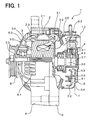
- an AC generator 1 for a vehicle includes a stator 2, a rotor 3, a brushing device 4, a rectifying device 5, a frame 6, a cover 7, and a pulley 8.
- the stator 2 has a stator core 21 and a three-phase stator coil 23 wound at a predetermined interval around slots formed in the stator core 21.
- the rotor 3 has a field coil 31, pole cores 32, and a rotor shaft 33.
- the field coil 31 is constructed of an insulated copper wire concentrically wound in a cylindrical shape.
- Each pole core 32 has six claw poles and covers the field coil 31 from opposite sides.
- the rotor shaft 33 passes through the center of the pose cores 32.
- An axial-flow type cooling fan 34 is welded to an end face of one of the pole cores 32 located adjacent to the pulley 8.
- the cooling fan 34 is used for blowing cooling air in the axial direction and in the radial direction.
- a centrifugal type cooling fan 35 is welded to an end face of the other pole core 32 for blowing cooling air in the radial direction.
- the brushing device 4 having brushes 41, 42 is used for passing exciting current from the rectifying device 5 to the field coil 31.
- the brushes 41, 42 are pressed against slip rings 36, 37 on the rotational shaft 33, respectively.
- the rectifying device 5 rectifies the three-phase AC voltage induced in the three-phase stator coil 23 to a DC voltage.
- the rectifying device 5 includes a terminal base 51, a positive-side radiation plate 52, a negative-side radiation plate 53, and rectifying elements (inserting members) 54, 55.
- the terminal base 51 contains electrodes for wiring.
- the positive-side and the negative-side radiation plates 52, 53 are arranged a predetermined distance away from each other.
- the rectifying elements 54, 55 are press-fitted in an engaging hole formed by punching in the respective radiation plates (receiving members) 52, 53.
- a frame 6 houses the stator 2 and the rotor 3.
- the rotor 3 is supported so that it can rotate about the rotator shaft 33.
- the stator 2 is fixed at a position a predetermined distance away from the outer peripheral of the pole cores 32.
- the frame 6 has cooling-air exit windows 61 and a cooling-air intake window 62.
- the exit windows 61 are opposed to the stator coil 23 projected in the axial direction from the end face of the stator core 21.
- the intake window 62 is located at the axial end face of the frame 6.
- the cover 7 covers parts arranged outside the frame 6 away from the pulley 8, including the brushing device 4, the rectifying device 5 and an IC regulator 12, for protecting the parts.
- the rotor 3 is rotated in the predetermined direction by torque transmitted from the engine (not shown) to the pulley 8 via a belt (not shown).
- an exciting voltage is applied to the field coil 31 while the rotor 3 is under rotation, the claw poles of the pole cores 32 are excited.
- a three-phase AC voltage is generated in the stator coil 23 and DC voltage is provided at the output terminal of the rectifying device 5.
- a method of press-fitting the rectifying element 54 in the positive-side radiation plate 52 will be discussed referring to Figs. 2 through 4.
- the rectifying element 55 is press-fitted in the negative-side radiation plate 53 in the same manner as the press-fitting of the rectifying element to the positive-said radiation plate 52. Therefore, it will not be discussed.
- the radiation plate 52 has an engaging hole 150 in which the rectifying element 54 is press-fitted.
- Grooves 152 are formed in an inner periphery of the radiation plate 52 in a circumferential direction and in a section adjacent to a sheared surface (the upper portion of Fig. 4).
- the grooves 152 are arranged in circumference or slanted off circumference and apart from each other in the direction that the engaging hole 150 is formed.
- the grooves 152 are not formed in a section adjacent to a fractured surface (the lower portion of Fig. 4).
- the rectifying element 54 includes a heat sink 250, a semiconductor pellet 252 and a lead 254.
- the heat sink 250 is a cylindrical metal base of the rectifying element 54 and used as an electrode. It has a knurl portion 256 on its outer periphery and a recess portion 258 at one of its ends. The bottom surface of the recess portion 258 is used as a soldering surface to which the semiconductor pellet 252 is soldered.
- the heat sink 250 is made of copper and its surface is plated for soldering and protection from oxidation due to contact with air.
- the hardness of the heat sink 250 which is equal to 160Hv, is higher than the hardness of the hardened radiation plate 52 around the hole, which is between 140 and 150Hv.
- One surface of the semiconductor pellet 252 is soldered to the heat sink 250, and the lead 254 is soldered to the other surface of the semiconductor pellet 252.
- each groove 152 is formed in the inner periphery of the radiation plate 52 in a portion adjacent to the side from which the rectifying element 54 is inserted (the lower side in Fig. 5).
- a depth of each groove 152 is defined so that a root diameter ⁇ 2 of the radiation plate 52 at the bottom of the groove 152 is substantially equal to an outer diameter ⁇ 3 of the heat sink 250 as shown in Fig. 6. If an inner diameter ⁇ 1 of the engaging hole 150 is set to about 13mm, the outer diameter ⁇ 3 is set 0.2mm larger than the inner diameter ⁇ 1.
- the root diameter ⁇ 2 is set equal to the outer diameter ⁇ 3 (the groove depth of 0.1mm), and the groove width is set to 0.1mm.
- the grooves 152 are formed in the radiation plate 52 that has a thickness of about 4mm. However, more than four grooves 152 may be formed and the grooves 152 may be uniformly arranged in the entire inner peripheral. Furthermore, it is preferable to change the shape and the distance between the grooves 152 as appropriate so that galling is less likely to occur even when the press-fitting process proceeds.
- the radiation plate 52 is prepared in a predetermined shape. Then, the engaging hole 150 is formed by punching press (engaging hole forming step). The four grooves 152 are formed in the inner periphery of the radiation plate 52 (groove forming step). The rectifying element 54 is press-fitted while an excess produced as the rectifying element 54 is further inserted in the hole 150 is released to the groove 152 (press-fitting step).
- the excess is released to the grooves 152 during the press-fitting of the rectifying element 54 in the hole 150. Moreover, the multiple grooves 152 enable the excess to be dividedly released into different grooves 152. Therefore, the excess does not build up in one place and galling is less likely to occur. Although galling is more likely to occur if both heat sink 250 and the radiation plate 52 are made of copper, the galling is effectively reduced with this configuration.
- the grooves 152 are formed in the inner periphery of the radiation plate 52 apart from each other in the direction that the engaging hole 150 is formed. Since the excess produced along the direction that the rectifying element 54 is press-fitted is dividedly released into the multiple grooves 152, the galling can be reduced.
- the grooves 152 are arranged in the inner periphery of the radiation plate 52 and on the side from which the rectifying element 54 is inserted for press-fitting. Thus, the excess produced by the press-fitting of the rectifying element 54 can be dividedly released from the early stage of the press-fitting step.
- the root diameter ⁇ 2 is set substantially equal to the outer diameter ⁇ 3. Therefore, the excess produced by the press-fitting of the rectifying element 54 can be dividedly released into each groove 152.
- the galling is less likely to occur during press-fitting of the rectifying element 54 into the radiation plate 52 with this configuration. Consequently, the physical and the electrical connections between the rectifying element 54 and the radiation plate 52 are maintained and the stress caused by the excess is reduced.
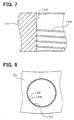
- a groove 154 is formed in a spiral in an inner periphery of the positive-side radiation plate 52 as shown in Fig. 7.
- the rest of configuration of the radiation plate 52 is the same as the first embodiment.
- the groove 154 performs the same function as the multiple grooves 152 of the first embodiment. It functions as if it is constructed of multiple grooves with respect to the direction in which the rectifying element 54 is inserted in the radiation plate 52. Thus, an excess produced by the press-fitting of the rectifying element 54 can be dividedly released to the groove 154.
- the groove 154 has an advantage over the grooves 152 in the groove forming step.
- the groove forming step of the groove 154 only one groove is formed in a series of machine works while multiple series of machine works are required to form the grooves 152. Namely, the groove forming step of the groove 154 is simplified in comparison with that of the grooves 152.
- multiple grooves 156 are formed in the inner periphery of the positive-side radiation plate 52.
- the grooves 156 are formed in the direction that the engaging hole 150 is formed and apart from each other in the circumferential direction of the radiation plate 52.
- the rest of configuration is the same as the first embodiment.
- each groove 156 has a depth of about 0.1mm and a width of about 0.1mm. If the inner diameter ⁇ 1 of the engaging hole 150 is about 13mm, it is preferable that about 40 to 78 grooves 156 are provided so that the necessary contact area for securing the rectifying element 54 in the radiation plate 52 is maintained.
- multiple grooves 158 are in the inner periphery of the positive-side radiation plate 52.
- the grooves 158 are slanted in the circumference direction of the radiation plate 52. With this configuration, an excess produced during the press-fitting of the rectifying element 54 to the radiation plate 52 is dividedly released into the grooves 158.
- a part of a hardened inner periphery surface of the positive-side radiation plate 52 is roughened. At least the surface in the area defined by an opening of the engaging hole 150 and a depth L, which is preferably larger than a thickness of the radiation plate 52, is roughened. An excess produced by the press-fitting of the rectifying element 54 moves in the direction that the rectifying element 54 is inserted. Thus, the surface adjacent to the opening is preferable to be roughened for effective releasing of the excess. An entire hardened inner periphery surface can be roughened.
- the radiation plate 52 is prepared in a predetermined shape and the engaging hole 150 is punched prior to the press-fitting of the rectifying element 54 (engaging hole forming step).
- engaging hole forming step a hardened inner periphery surface of the radiation plate 52 is created.
- the hardened inner periphery surface of the radiation plate 52 is then roughened (surface roughening step).
- the rectifying element 54 is press-fitted in the direction that the engaging hole 150 is formed (press-fitting step).
- the surface is roughened by wire brushing, sanding, or lathe turning.
- wire brushing the surface is scratched with a wire brush.
- sanding the surface is sanded with a sand paper.
- lathe turning the surface is turned by a lathe turning machine.
- flaws having a depth of 10 to 15 ⁇ m are formed on the surface, and the roughness of the surface becomes equal to or larger than 20Z.
- the hardness of the surface is reduced to about 80Hv, which is substantially equal to the hardness of other portions of the radiation plate 52. Galling caused by the excess hardened during the press-fitting the rectifying element 54 is reduced. Therefore, the physical and the electrical connections between the rectifying element 54 and the radiation plate 52 are maintained. Moreover, stress due to the excess is reduced.
- the inserting member is not limited to a heat sink of a rectifying element.
- the grooves can be formed in a section of the radiation plate adjacent to the fractured surface.
- Forming grooves in the inner periphery of the radiation plate 52 and roughening the hardened inner periphery surface of the radiation plate 52 may be performed in one step.
- the heat sink 250 of the rectifying element 54 and the positive-electrode radiation plate 52 are made of a material other than copper, galling can be reduced with the present invention.
Landscapes
- Engineering & Computer Science (AREA)
- Power Engineering (AREA)
- Mechanical Engineering (AREA)
- Synchronous Machinery (AREA)
- Automatic Assembly (AREA)
- Cooling Or The Like Of Semiconductors Or Solid State Devices (AREA)
- Rectifiers (AREA)
Abstract
Description
Claims (15)
- A press-fitting method for press-fitting an inserting member (54, 55, 250) in a receiving member (52, 53), comprising:forming an engaging hole in the receiving member (52, 53);forming at least one groove (152, 154, 156, 158) in an inner periphery of the receiving member (52, 53), the inner periphery created by the engaging hole; andpress-fitting the inserting member (54, 55) in the engaging hole while releasing an excess into the groove (152, 154, 156, 158).
- The press-fitting method according to claim 1, wherein:the inserting member (54, 55, 250) and the receiving member (52, 53) are made of copper;the inserting member (54, 55, 250) has a hardness higher than a hardness of the receiving member (52, 53); andthe engaging hole forming step is performed by punching.
- The press-fitting method according to claim 1 or 2, wherein:the groove forming step forms a plurality of grooves (152, 154) in a circumferential direction; andthe grooves (152, 154) are arranged apart from each other in the direction that the engaging hole is formed.
- The press-fitting method according to claim 3, wherein the grooves (154) are slanted off circumference.
- The press-fitting method according to claim 1 or 2, wherein the forming step forms a plurality of grooves (156, 158)in the direction that the engaging hole is formed.
- The press-fitting method according to claim 5, wherein the grooves (156, 158) are arranged apart from each other in the circumferential direction.
- The press-fitting method according to claim 5, wherein the grooves (158) are slanted in the circumferential direction.
- The press-fitting method according to any one of claims 1 through 7, wherein the groove forming step forms a plurality of grooves (152, 154, 156, 158) so that a root diameter (2) of the receiving member at a bottom of each groove is substantially equal to an outer diameter (3) of the inserting member (54, 55, 250).
- A press-fitting method for press-fitting an inserting member (54, 55, 250) in a receiving member (52, 53), comprising:punching an engaging hole in the receiving member (52, 53) while creating a hardened inner periphery surface on the receiving member (52, 53);roughening the hardened inner periphery surface; andpress-fitting the inserting member (54, 55, 250) in the engaging hole, wherein the inserting member (54, 55, 250) has a hardness higher than a hardness of the receiving member (52, 53).
- The press-fitting method according to claim 9, wherein the inserting member (54, 55, 250) and the receiving member (52, 53) are made of copper.
- The press-fitting method according to any one of claims 1 trough 9, wherein:the inserting member (250) is a base of a rectifying element (54, 55) included in an alternate current power generator (1) and used as an electrode; andthe receiving member (52, 53) is a radiation plate (52, 53) of the rectifying element (54, 55).
- The press-fitting method according to claim 1, wherein the groove (154) forming step forms a groove in a spiral.
- A rectifying device (5) used for a vehicular alternate current power generator (1) having a stator (2) and a rotor (3), wherein the rectifying device (5) has a rectifying element (54, 55) for rectifying an alternate current voltage induced in a stator coil (23) of the stator (2) when the rotor (3) is rotated and a radiation plate (52, 53), wherein:the radiation plate (52, 53) has an engaging hole that creates an inner periphery of the radiation plate (52, 53);the inner periphery of the radiation plate (52, 53) has a plurality of grooves (152, 154, 156, 158); andthe rectifying element (54, 55) press-fitted in the engaging hole of the radiation plate (52, 53).
- A rectifying device (5) included in a vehicular alternate current power generator (1) having a stator (2) and a rotor (3), wherein the rectifying device (5) has a rectifying element (54, 55) that rectifies an alternate current voltage induced in a stator coil (23) of the stator (2) when the rotor (3) is rotated and a radiation plate (52, 53), characterized in that:the radiation plate (52, 53) has an engaging hole that creates a hardened inner periphery of the radiation plate (52, 53);the hardened inner periphery of the radiation plate (52, 53) is roughened; andthe rectifying element (54, 55) is press-fitted in the engaging hole of the radiation plate (52, 53).
- A press-fitting method for press-fitting an inserting member (54, 55, 250) in a receiving member (52, 53), comprising:punching an engaging hole in the receiving member (52, 53) while forming a sheared surface and a fractured surface on an inner periphery of the receiving member (52, 53), the inner periphery created by the hole;forming at least one groove (152, 154, 156, 158) in the inner periphery; andpress-fitting the inserting member (54, 55, 250) in the receiving member by inserting the inserting member (54, 55, 250) form an end of the receiving member (52, 53) adjacent to the sheared surface.
Applications Claiming Priority (2)
| Application Number | Priority Date | Filing Date | Title |
|---|---|---|---|
| JP2002364485A JP2004195567A (en) | 2002-12-16 | 2002-12-16 | Press-in material, press-in method of rectifying element and rectifier |
| JP2002364485 | 2002-12-16 |
Publications (3)
| Publication Number | Publication Date |
|---|---|
| EP1437770A2 true EP1437770A2 (en) | 2004-07-14 |
| EP1437770A3 EP1437770A3 (en) | 2004-09-22 |
| EP1437770B1 EP1437770B1 (en) | 2009-03-25 |
Family
ID=32501093
Family Applications (1)
| Application Number | Title | Priority Date | Filing Date |
|---|---|---|---|
| EP03028735A Expired - Lifetime EP1437770B1 (en) | 2002-12-16 | 2003-12-12 | Rectifying device having press-fitted member |
Country Status (4)
| Country | Link |
|---|---|
| US (1) | US7282824B2 (en) |
| EP (1) | EP1437770B1 (en) |
| JP (1) | JP2004195567A (en) |
| DE (1) | DE60326810D1 (en) |
Cited By (4)
| Publication number | Priority date | Publication date | Assignee | Title |
|---|---|---|---|---|
| FR2940379A1 (en) * | 2008-12-19 | 2010-06-25 | Stephane Rey | Needle bush for rotatively guiding outer part, has outer ring having outer cylindrical face including hollow elements, where diameter corresponding to bottom of elements in hollows is less than nominal diameter of outer cylindrical face |
| CN102868259A (en) * | 2011-07-09 | 2013-01-09 | 株式会社电装 | Alternator for vehicle |
| WO2014083609A1 (en) * | 2012-11-27 | 2014-06-05 | 三菱電機株式会社 | Method for manufacturing rectifier and rectifier |
| DE102013105807A1 (en) * | 2013-06-05 | 2014-12-11 | Dr. Ing. H.C. F. Porsche Aktiengesellschaft | Bearing receiver with bearings |
Families Citing this family (8)
| Publication number | Priority date | Publication date | Assignee | Title |
|---|---|---|---|---|
| JP4693385B2 (en) * | 2004-09-29 | 2011-06-01 | 三菱電機株式会社 | AC generator for vehicles |
| JP4517991B2 (en) * | 2005-09-14 | 2010-08-04 | 株式会社ジェイテクト | Guide roller device and guide roller device manufacturing method |
| JP4600366B2 (en) * | 2006-08-29 | 2010-12-15 | 株式会社デンソー | Vehicle alternator |
| KR101163569B1 (en) | 2008-06-09 | 2012-07-09 | 한국델파이주식회사 | Alternator for a vehicle |
| TWM407546U (en) * | 2010-11-11 | 2011-07-11 | Victory Ind Corp | Improved structure of heat sink module |
| JP5439430B2 (en) * | 2011-05-17 | 2014-03-12 | 日立オートモティブシステムズ株式会社 | AC generator for vehicles |
| JP5924142B2 (en) * | 2011-07-09 | 2016-05-25 | 株式会社デンソー | AC generator for vehicles |
| DE102013225984B4 (en) * | 2013-12-16 | 2017-03-23 | Schaeffler Technologies AG & Co. KG | Hydraulic tensioning device for a traction mechanism drive |
Family Cites Families (28)
| Publication number | Priority date | Publication date | Assignee | Title |
|---|---|---|---|---|
| GB256353A (en) | 1925-05-27 | 1926-08-12 | Douglas Motors Ltd | Improvements in the manufacture of cam mechanism |
| US3198874A (en) | 1961-01-23 | 1965-08-03 | Standard Pressed Steel Co | Semi-conductor housings and method of making the same |
| US4118134A (en) * | 1974-04-08 | 1978-10-03 | Lescoa, Inc. | Fastener joint and method thereof |
| DE2603786C2 (en) | 1976-01-31 | 1983-01-13 | Robert Bosch Gmbh, 7000 Stuttgart | Rectifier arrangement |
| SE416664B (en) | 1977-03-08 | 1981-01-26 | Gkn Stenman Ab | lock rower |
| US4375333A (en) * | 1980-10-16 | 1983-03-01 | Leeds & Northrup Company | Microprocessor directed optical pyrometer |
| DE3124692A1 (en) * | 1981-06-24 | 1983-01-13 | Robert Bosch Gmbh, 7000 Stuttgart | "SEMICONDUCTOR RECTIFIER" |
| JPS5968586A (en) | 1982-10-13 | 1984-04-18 | Hitachi Ltd | Rotary vane type compressor and manufacture thereof |
| US4943178A (en) * | 1986-05-08 | 1990-07-24 | Illinois Tool Works, Inc. | Mounting structure for rotating bodies |
| JPH0229262Y2 (en) | 1986-09-30 | 1990-08-06 | ||
| JPH0529370Y2 (en) * | 1987-01-19 | 1993-07-28 | ||
| JPH0672616B2 (en) * | 1987-04-21 | 1994-09-14 | 株式会社ゼクセル | Steel shaft composite aluminum alloy rotor |
| DE3931447A1 (en) * | 1989-09-21 | 1991-04-04 | Skf Gmbh | ARRANGEMENT FOR THE AXIAL LOCKING OF A ROLLER BEARING RING |
| JPH078914Y2 (en) * | 1988-12-09 | 1995-03-06 | 光洋精工株式会社 | Coupling structure of shaft and ring |
| DE69104016T3 (en) * | 1990-11-19 | 1999-09-02 | Nippon Piston Ring Co. | Machine element with at least one connecting part fastened with pressure on a shaft. |
| JP3279329B2 (en) | 1991-11-01 | 2002-04-30 | クルップ・プレスタ・アーゲー | Camshaft manufacturing equipment |
| US5207525A (en) * | 1992-04-27 | 1993-05-04 | Delco Electronics Corporation | Instrument spindle with relief design |
| JP2790614B2 (en) | 1994-09-02 | 1998-08-27 | 共栄精工株式会社 | Ring forming method by cold pressing |
| DE19517258A1 (en) * | 1995-05-11 | 1996-11-14 | Alpha Getriebebau Gmbh | Shaft attachment |
| JP3284887B2 (en) * | 1995-06-23 | 2002-05-20 | トヨタ自動車株式会社 | Tight fitting method and tight fitting device |
| FR2737618B1 (en) | 1995-08-02 | 1997-10-24 | Valeo Equip Electr Moteur | ALTERNATOR COMPRISING ADAPTERS FOR RECTIFIER BRIDGE DIODES, PARTICULARLY FOR MOTOR VEHICLE, AND ADAPTER FOR SUCH ALTERNATOR |
| JP3426101B2 (en) | 1997-02-25 | 2003-07-14 | 三菱電機株式会社 | Rectifier |
| US5882131A (en) | 1997-03-11 | 1999-03-16 | Hewlett-Packard Company | Printer drive roller with grit-blasted surface |
| JP2000042845A (en) | 1998-07-28 | 2000-02-15 | Toyota Motor Corp | Inertia injection method |
| JP2002119029A (en) | 2000-10-12 | 2002-04-19 | Denso Corp | AC generator for vehicles |
| US6661662B2 (en) | 2001-02-21 | 2003-12-09 | Transpo Electronics, Inc. | Vehicular modular design multiple application rectifier assembly |
| JP4056751B2 (en) * | 2002-01-28 | 2008-03-05 | 株式会社デンソー | AC generator rectifier for vehicle |
| US6731031B2 (en) * | 2002-10-08 | 2004-05-04 | Delphi Technologies, Inc. | Apparatus and method for heat sink device |
-
2002
- 2002-12-16 JP JP2002364485A patent/JP2004195567A/en active Pending
-
2003
- 2003-12-12 US US10/733,456 patent/US7282824B2/en not_active Expired - Fee Related
- 2003-12-12 DE DE60326810T patent/DE60326810D1/en not_active Expired - Lifetime
- 2003-12-12 EP EP03028735A patent/EP1437770B1/en not_active Expired - Lifetime
Cited By (5)
| Publication number | Priority date | Publication date | Assignee | Title |
|---|---|---|---|---|
| FR2940379A1 (en) * | 2008-12-19 | 2010-06-25 | Stephane Rey | Needle bush for rotatively guiding outer part, has outer ring having outer cylindrical face including hollow elements, where diameter corresponding to bottom of elements in hollows is less than nominal diameter of outer cylindrical face |
| CN102868259A (en) * | 2011-07-09 | 2013-01-09 | 株式会社电装 | Alternator for vehicle |
| WO2014083609A1 (en) * | 2012-11-27 | 2014-06-05 | 三菱電機株式会社 | Method for manufacturing rectifier and rectifier |
| DE102013105807A1 (en) * | 2013-06-05 | 2014-12-11 | Dr. Ing. H.C. F. Porsche Aktiengesellschaft | Bearing receiver with bearings |
| DE102013105807B4 (en) | 2013-06-05 | 2023-11-09 | Dr. Ing. H.C. F. Porsche Aktiengesellschaft | Bearing holder with bearing |
Also Published As
| Publication number | Publication date |
|---|---|
| JP2004195567A (en) | 2004-07-15 |
| EP1437770A3 (en) | 2004-09-22 |
| DE60326810D1 (en) | 2009-05-07 |
| US7282824B2 (en) | 2007-10-16 |
| EP1437770B1 (en) | 2009-03-25 |
| US20040150273A1 (en) | 2004-08-05 |
Similar Documents
| Publication | Publication Date | Title |
|---|---|---|
| EP1437770B1 (en) | Rectifying device having press-fitted member | |
| EP0823769A1 (en) | Electric rotary machine having heat conductive member | |
| JP2000197303A (en) | AC generator for vehicles | |
| EP1760863B1 (en) | Automotive alternator with rectifier having high-strength heat sinks | |
| US6160335A (en) | Terminal arrangement of vehicle AC generator | |
| US7855480B2 (en) | Rectifier device for automotive alternator | |
| JP4284860B2 (en) | Vehicle alternator | |
| JP3775235B2 (en) | AC generator for vehicles | |
| JP3675048B2 (en) | Vehicle alternator | |
| KR101073322B1 (en) | Dynamo-electric machine | |
| JP4626665B2 (en) | Rectifier | |
| JP2009018417A (en) | Press-in method of press-fitting material | |
| JP4407035B2 (en) | Method for manufacturing vehicle alternator | |
| JP2002119029A (en) | AC generator for vehicles | |
| JP2010074877A (en) | Manufacturing method for heat sinks for rotating electrical machines and rectifiers | |
| US20040256925A1 (en) | Rectifier for a vehicle alternator | |
| JP5924142B2 (en) | AC generator for vehicles | |
| US20070103012A1 (en) | Method of manufacturing terminal assembly of alternator for vehicles and terminal assembly manufactured by the method | |
| JP3724375B2 (en) | Vehicle alternator | |
| JP4487739B2 (en) | Vehicle alternator | |
| JP4483842B2 (en) | Vehicle alternator | |
| JP6056555B2 (en) | AC generator rectifier for vehicle | |
| JP2004072852A (en) | Rotor of rotating electric machine and method of manufacturing the same | |
| JP4886815B2 (en) | Rectifier for rotating electrical machine and fixing method of rectifier element | |
| JP3945285B2 (en) | Semiconductor device |
Legal Events
| Date | Code | Title | Description |
|---|---|---|---|
| PUAI | Public reference made under article 153(3) epc to a published international application that has entered the european phase |
Free format text: ORIGINAL CODE: 0009012 |
|
| AK | Designated contracting states |
Kind code of ref document: A2 Designated state(s): AT BE BG CH CY CZ DE DK EE ES FI FR GB GR HU IE IT LI LU MC NL PT RO SE SI SK TR |
|
| AX | Request for extension of the european patent |
Extension state: AL LT LV MK |
|
| PUAL | Search report despatched |
Free format text: ORIGINAL CODE: 0009013 |
|
| AK | Designated contracting states |
Kind code of ref document: A3 Designated state(s): AT BE BG CH CY CZ DE DK EE ES FI FR GB GR HU IE IT LI LU MC NL PT RO SE SI SK TR |
|
| AX | Request for extension of the european patent |
Extension state: AL LT LV MK |
|
| 17P | Request for examination filed |
Effective date: 20040910 |
|
| 17Q | First examination report despatched |
Effective date: 20041111 |
|
| AKX | Designation fees paid |
Designated state(s): DE FR IT |
|
| 17Q | First examination report despatched |
Effective date: 20041111 |
|
| GRAP | Despatch of communication of intention to grant a patent |
Free format text: ORIGINAL CODE: EPIDOSNIGR1 |
|
| RTI1 | Title (correction) |
Free format text: RECTIFYING DEVICE HAVING PRESS-FITTED MEMBER |
|
| GRAS | Grant fee paid |
Free format text: ORIGINAL CODE: EPIDOSNIGR3 |
|
| GRAA | (expected) grant |
Free format text: ORIGINAL CODE: 0009210 |
|
| AK | Designated contracting states |
Kind code of ref document: B1 Designated state(s): DE FR IT |
|
| REF | Corresponds to: |
Ref document number: 60326810 Country of ref document: DE Date of ref document: 20090507 Kind code of ref document: P |
|
| PLBE | No opposition filed within time limit |
Free format text: ORIGINAL CODE: 0009261 |
|
| STAA | Information on the status of an ep patent application or granted ep patent |
Free format text: STATUS: NO OPPOSITION FILED WITHIN TIME LIMIT |
|
| 26N | No opposition filed |
Effective date: 20091229 |
|
| REG | Reference to a national code |
Ref country code: FR Ref legal event code: PLFP Year of fee payment: 13 |
|
| REG | Reference to a national code |
Ref country code: FR Ref legal event code: PLFP Year of fee payment: 14 |
|
| PGFP | Annual fee paid to national office [announced via postgrant information from national office to epo] |
Ref country code: DE Payment date: 20161213 Year of fee payment: 14 |
|
| PGFP | Annual fee paid to national office [announced via postgrant information from national office to epo] |
Ref country code: FR Payment date: 20161222 Year of fee payment: 14 |
|
| PGFP | Annual fee paid to national office [announced via postgrant information from national office to epo] |
Ref country code: IT Payment date: 20161223 Year of fee payment: 14 |
|
| REG | Reference to a national code |
Ref country code: DE Ref legal event code: R119 Ref document number: 60326810 Country of ref document: DE |
|
| REG | Reference to a national code |
Ref country code: FR Ref legal event code: ST Effective date: 20180831 |
|
| PG25 | Lapsed in a contracting state [announced via postgrant information from national office to epo] |
Ref country code: IT Free format text: LAPSE BECAUSE OF NON-PAYMENT OF DUE FEES Effective date: 20171212 Ref country code: DE Free format text: LAPSE BECAUSE OF NON-PAYMENT OF DUE FEES Effective date: 20180703 Ref country code: FR Free format text: LAPSE BECAUSE OF NON-PAYMENT OF DUE FEES Effective date: 20180102 |