EP1437716A1 - Storage medium type identifying method - Google Patents
Storage medium type identifying method Download PDFInfo
- Publication number
- EP1437716A1 EP1437716A1 EP02802016A EP02802016A EP1437716A1 EP 1437716 A1 EP1437716 A1 EP 1437716A1 EP 02802016 A EP02802016 A EP 02802016A EP 02802016 A EP02802016 A EP 02802016A EP 1437716 A1 EP1437716 A1 EP 1437716A1
- Authority
- EP
- European Patent Office
- Prior art keywords
- level
- reproduction
- reproduction output
- recording medium
- recording
- Prior art date
- Legal status (The legal status is an assumption and is not a legal conclusion. Google has not performed a legal analysis and makes no representation as to the accuracy of the status listed.)
- Granted
Links
Images







Classifications
-
- G—PHYSICS
- G11—INFORMATION STORAGE
- G11B—INFORMATION STORAGE BASED ON RELATIVE MOVEMENT BETWEEN RECORD CARRIER AND TRANSDUCER
- G11B7/00—Recording or reproducing by optical means, e.g. recording using a thermal beam of optical radiation by modifying optical properties or the physical structure, reproducing using an optical beam at lower power by sensing optical properties; Record carriers therefor
- G11B7/08—Disposition or mounting of heads or light sources relatively to record carriers
- G11B7/085—Disposition or mounting of heads or light sources relatively to record carriers with provision for moving the light beam into, or out of, its operative position or across tracks, otherwise than during the transducing operation, e.g. for adjustment or preliminary positioning or track change or selection
- G11B7/08505—Methods for track change, selection or preliminary positioning by moving the head
- G11B7/08511—Methods for track change, selection or preliminary positioning by moving the head with focus pull-in only
-
- G—PHYSICS
- G11—INFORMATION STORAGE
- G11B—INFORMATION STORAGE BASED ON RELATIVE MOVEMENT BETWEEN RECORD CARRIER AND TRANSDUCER
- G11B19/00—Driving, starting, stopping record carriers not specifically of filamentary or web form, or of supports therefor; Control thereof; Control of operating function ; Driving both disc and head
- G11B19/02—Control of operating function, e.g. switching from recording to reproducing
- G11B19/12—Control of operating function, e.g. switching from recording to reproducing by sensing distinguishing features of or on records, e.g. diameter end mark
-
- G—PHYSICS
- G11—INFORMATION STORAGE
- G11B—INFORMATION STORAGE BASED ON RELATIVE MOVEMENT BETWEEN RECORD CARRIER AND TRANSDUCER
- G11B19/00—Driving, starting, stopping record carriers not specifically of filamentary or web form, or of supports therefor; Control thereof; Control of operating function ; Driving both disc and head
- G11B19/02—Control of operating function, e.g. switching from recording to reproducing
- G11B19/12—Control of operating function, e.g. switching from recording to reproducing by sensing distinguishing features of or on records, e.g. diameter end mark
- G11B19/127—Control of operating function, e.g. switching from recording to reproducing by sensing distinguishing features of or on records, e.g. diameter end mark involving detection of the number of sides, e.g. single or double, or layers, e.g. for multiple recording or reproducing layers
-
- G—PHYSICS
- G11—INFORMATION STORAGE
- G11B—INFORMATION STORAGE BASED ON RELATIVE MOVEMENT BETWEEN RECORD CARRIER AND TRANSDUCER
- G11B7/00—Recording or reproducing by optical means, e.g. recording using a thermal beam of optical radiation by modifying optical properties or the physical structure, reproducing using an optical beam at lower power by sensing optical properties; Record carriers therefor
- G11B2007/0003—Recording, reproducing or erasing systems characterised by the structure or type of the carrier
- G11B2007/0009—Recording, reproducing or erasing systems characterised by the structure or type of the carrier for carriers having data stored in three dimensions, e.g. volume storage
- G11B2007/0013—Recording, reproducing or erasing systems characterised by the structure or type of the carrier for carriers having data stored in three dimensions, e.g. volume storage for carriers having multiple discrete layers
-
- G—PHYSICS
- G11—INFORMATION STORAGE
- G11B—INFORMATION STORAGE BASED ON RELATIVE MOVEMENT BETWEEN RECORD CARRIER AND TRANSDUCER
- G11B7/00—Recording or reproducing by optical means, e.g. recording using a thermal beam of optical radiation by modifying optical properties or the physical structure, reproducing using an optical beam at lower power by sensing optical properties; Record carriers therefor
Definitions
- the present invention relates to a device for determining type of recording media, a method for determining type of recording media, a computer-readable recording medium having recorded therein a program for determining type of recording media, and a program for determining type of recording media, all of which are preferably applicable to video game console, DVD device, magneto-optical disc device, magnetic disc device, and the like.
- a conventionally known recording medium having a two-dimensional structure where a recording layer comprises a "single-layer", such as a CD-ROM or so forth.
- the recording medium with two-dimensional structure of "single-layer” there is a known recording medium (three-dimensional recording medium) having a three-dimensional structure of "multi-layer” where a plurality of recording layers are laminated, such as a DVD, FMD (Fluorescent Multi-layer Disc) or so forth.
- Device for handling such three-dimensional recording medium must be compatible both for single-layer recording medium having a single recording layer and multi-layer recording medium having two or more recording layers.
- Such device aimed at handling both of the single-layer and multi-layer recording media should, however, alter settings of laser level or gain of the individual signals between the both.
- the device for handling the three-dimensional recording medium determines, in advance of recording and reproduction of a recording medium, whether the recording medium is of single-layer or multi-layer, and to alter settings for various units based on the determined result to thereby effect recording and reproduction to or from such recording medium.
- sum signals RF signals
- making a gradual approach of an optical pick-up from a predetermined position towards a DVD can first generate a reproduction signal (disc surface reflection signal) ascribable to the light reflected on a protective film of the disc typically made from polycarbonate, and can then generate a reproduction signal (signal plane reflection signal) ascribable to the light reflected on a recording layer (signal plane) of the disc.
- a reproduction signal disc surface reflection signal
- signal signal plane reflection signal
- FIG. 1 shows a disc surface reflection signal and a signal plane reflection signal of a DVD having a single recording layer (referred to as a single-layer DVD, hereinafter).
- FIG. 2 shows a disc surface reflection signal and a signal plane reflection signal of a DVD having two or more recording layers (referred to as a multi-layer DVD, hereinafter).
- the signal plane reflection signal for the single-layer DVD has a single peak which is ascribable to the single recording plane and the peak level is large, but the signal plane reflection signal for the multi-layer DVD has a plurality of peaks corresponding to a plurality of recording planes (two peaks because of two recording layers, for the case shown in FIG. 2), and the peak level is lower than that of the single-layer DVD (reflection level P1 > reflection level P2) which is attributable to difference in transmittancy of light of the individual layers, or to random scattering of light by gap between the adjacent layers.
- the level determination method conveniently sets a threshold value at an intermittent level between the peak levels obtained for the single-layer DVD and multi-layer DVD, and a DVD is determined as a single-layer one if the level of the signal plane reflection signal thereof is not less than the threshold value, but as a multi-layer DVD or low reflection recording medium (for example, phase-change-type disc such as DVD-RW) if the level of the signal plane reflection signal thereof is less than the threshold value.
- a threshold value at an intermittent level between the peak levels obtained for the single-layer DVD and multi-layer DVD
- a DVD is determined as a single-layer one if the level of the signal plane reflection signal thereof is not less than the threshold value, but as a multi-layer DVD or low reflection recording medium (for example, phase-change-type disc such as DVD-RW) if the level of the signal plane reflection signal thereof is less than the threshold value.
- the focus error counting method conveniently sets a high-level threshold value (FcmpH Slice Level) for such focus error signal, and generates a an FcmpH signal that reaches high-level during a period for which the focus error signal exceeds the high-level threshold value.
- FcmpH Slice Level a high-level threshold value
- the focus error counting method conveniently sets a low-level threshold value (FcmpL Slice Level) for such focus error signal, and generates an FcmpL signal that reaches high-level during a period for which the focus error signal is lower than the low-level threshold value.
- FcmpL Slice Level a low-level threshold value
- the single-layer DVD gives only one pulse of the FcmpH signal or FcmpL signal as shown in FIG. 3, and in contrast the multi-layer DVD gives a plurality of pulses of the FcmpH signal or FcmpL signal as shown in FIG. 4 (for the exemplary case shown in FIG. 4 gives two pulses of the FcmpH signal or FcmpL signal since the DVD has two recording layers).
- the disc is determined as a single-layer DVD if the number of pulses is unity, and is determined as a multi-layer DVD if the number of pulses is two or more. This allows determination whether the DVD has a single or plurality of recording layers.
- the "level determination method" is valuable for assessing various gain setting upon recording/reproduction, problems of the method reside in that it requires optimum level setting of the threshold values for every units for a successful determination of single-layer and multi-layer discs, and also in that it only has a narrow allowance for variation in reflectivity of the recording medium due to time-dependent degradation.
- the "focus error counting method” suffers from difficulty in setting high-level threshold value (FcmpH Slice Level) or low-level threshold value (FcmpL Slice Level) to an optimum level because of the reasons the same as the "level determination method", which has undesirably resulted in incorrect generation of pulses for the counting, and incorrect counting of the number of pulses due to the occurrence of fake pulse.
- the focus error signal may sometimes have waviness immediately before and after the focal point as shown in FIGs. 3 and 4 depending on mode for detecting focus error, optical design of the optical pick-up, temperature change, signal gain and so forth.
- the waviness indicated by dotted line in FIGs. 3 and 4 will be causative of fake pulse, which otherwise should not appear, if the level of the waviness exceeds the high-level threshold value (FcmpH Slice Level) or becomes lower than the low-level threshold value (FcmpL Slice Level).
- the fake pulse may give the count value for the FcmpH signal or FcmpL signal different from the true count value thereof, which obstructs correct single-layer/multi-layer determination.
- the count value may be given as "2", which should be “1” in true, since also the fake pulse indicated by the dotted line is included in the counting, so that the single-layer DVD may be misjudged as a multi-layer DVD.
- the present invention was proposed to address the foregoing problems, and an object thereof is to provide a novel single-layer/multi-layer determination method which is substitutable for the conventional "focus error counting method” and "level determination method”, and is to provide a device for determining type of recording media, a method for determining type of recording media, a computer-readable recording medium having recorded thereon a program for determining type of recording media, and a program for determining type of recording media, all of which can correctly determine the number of recording layers while not being affected by variation in property of the units, variation in reflectivity of recording medium, variation in the ambient temperature and fake pulse ascribable to waviness in focus error signal.
- the present invention conveniently sets a perpendicular scanning period for which the recording medium is scanned perpendicular to the recording surface, and detects a reproduction output level based on the amplitude of a reproduction output obtained during this period.
- the number of those having reproduction output level larger than a predetermined level is counted, whereby a recording medium is determined as having recording layers in a number same as the number of the accepted reproduction outputs.
- the present invention is applicable to a video game console for executing a video game through reproducing a video game program recorded in a recording medium, for which both of single-layer medium having a single recording layer and multi-layer medium having a plurality of recording layers are available.
- the single-layer recording medium a CD, a DVD having one recording layer on one side only (single-layer DVD), and a DVD having one recording layer on each side (double-sided single-layer DVD) are included.
- a DVD having a plurality of recording layers on one side only (one sided multi-layer DVD), a DVD having a plurality of recording layers on each side (double-sided multi-layer DVD), and a phase change disc (DVD-R, DVD-RW) are included.
- a video game console has, besides functions for executing video games, a disc type (single-layer/multi-layer) determination function for determining type of a disc 1, as shown in FIG. 5, by determining the number of recording layer of the disc 1.
- a disc type single-layer/multi-layer
- the video game console of this embodiment has a spindle motor 2 for rotating the disc 1 at a constant angular velocity or at a constant linear velocity, and an optical pick-up 3 for irradiating laser beam to the disc 1 and for generating, based on reflection of such laser beam, photo-detector signals which include focus error signal, tracking error signal, RF signal (sum signal for signal decoding) and PI signal (a signal obtained by extracting a low-frequency component of the sum signal) for expressing reflectivity of the disc 1.
- photo-detector signals which include focus error signal, tracking error signal, RF signal (sum signal for signal decoding) and PI signal (a signal obtained by extracting a low-frequency component of the sum signal) for expressing reflectivity of the disc 1.
- the video game console also has a feed motor 4 for moving the optical pick-up 3, in a controlled manner, along the radial direction of the disc 1, and an RF amplifier 5 for calculating and amplifying the photo-detector signals from the optical pick-up 3 at a predetermined gain and for outputting the resultant signal.
- the video game console still also has an FcmpH comparator 7 for generating FcmpH signal obtained by binary coding of the focus error signal based on a high-level threshold value set for such focus error signal fed via the RF amplifier 5; an FcmpL comparator 8 for generating FcmpL signal obtained by binary coding of the focus error signal based on a low-level threshold value set for such focus error signal fed via the RF amplifier 5; and a peak bottom detector 6 for detecting a peak level and bottom level of the focus error signal fed via the RF amplifier 5 based on the FcmpH signal and FcmpL signal generated by the comparators 7 and 8, respectively.
- an FcmpH comparator 7 for generating FcmpH signal obtained by binary coding of the focus error signal based on a high-level threshold value set for such focus error signal fed via the RF amplifier 5
- an FcmpL comparator 8 for generating FcmpL signal obtained by binary coding of the focus error signal based on a low-level threshold value set for such focus
- the video game console still also has a peak detector 9 for detecting a peak level of the disc reflection signal (PI signal) which expresses reflectivity of the disc and is fed via the RF amplifier 5; an FOK comparator 10 for generating FOK signal by binary coding of the PI signal based on a predetermined threshold value; and a signal-decoding DSP 11 for decoding the RF signal fed via the RF amplifier 5.
- PI signal disc reflection signal
- the video game console still also has a servo processing DSP 12 for controlling rotation of the spindle motor 2 and movement of the optical pick-up 3, which are effected through controlling a driver 13 based on the focus error signal, tracking error signal, RF signal, PI signal and so forth fed from the RF amplifier 5; and a servo processing microcomputer 14 responsible for setting the individual threshold values for the FcmpH comparator 7, FcmpL comparator 8 and FOK comparator 10, respectively.
- a servo processing DSP 12 for controlling rotation of the spindle motor 2 and movement of the optical pick-up 3, which are effected through controlling a driver 13 based on the focus error signal, tracking error signal, RF signal, PI signal and so forth fed from the RF amplifier 5; and a servo processing microcomputer 14 responsible for setting the individual threshold values for the FcmpH comparator 7, FcmpL comparator 8 and FOK comparator 10, respectively.
- the optical pick-up 3 has, besides the foregoing photo-detector, a biaxial actuator 15 and an objective lens 16.
- FIG. 6 is a flow chart showing a process flow of such reproduction process.
- a program for executing such reproduction process shown in this flow chart is preliminarily stored in a ROM 17 provided within a main body of the video game console, which is to be read out by the servo processing microcomputer 14 from the ROM 17 and to be executed under control.
- Another possible way may be such that the program for executing the reproduction process is preliminarily stored in the disc 1, the servo processing microcomputer 14 reads the program out from the disc 1 and stores it under control in a storage section such as a RAM, HDD or the like only for the first time, whereby reproduction of information recorded in the disc 1 can be started for the next time or thereafter using such program for executing the reproduction process stored in the storage section.
- a storage section such as a RAM, HDD or the like
- Still another possible way may be such that the program for executing the reproduction process shown in the flow chart is downloaded from a server machine on a network such as the Internet into a storage section such as a RAM, HDD or the like, and the execution program is read out from the storage section and executed under control by the servo processing microcomputer 14.
- the reproduction process shown in the flow chart in FIG. 6 is activated when loading of the disc 1 is detected by the servo processing microcomputer 14 of the video game console, and the process step then advances to step S 1.
- step S1 the servo processing microcomputer 14 determines whether the disc 1 loaded on the video game console is a CD or DVD.
- depth of the recording layer of a CD from the disc surface thereof is larger than that of a DVD, so that the servo processing microcomputer 14 makes the servo processing DSP 12 and the driver 13 control movement of a focal point of the laser beam to be irradiated onto the disc 1 so as to gradually approach the recording layer of the disc 1 from a position distant from the recording layer.
- the optical pick-up 3 Corresponding to the movement under control, the optical pick-up 3 generates a disc reflection signal (PI signal) as shown in FIG. 7.
- PI signal disc reflection signal
- the PI signal first appears with a small level when the focal point of the laser beam falls on the surface of the disc 1, and then appears with a large level when the focal point of the laser beam reaches the recording layer in the disc 1.
- a time period since the detection of the small-level PI signal to the detection of the large-level PI signal is longer than that for a DVD.
- the servo processing DSP 12 thus receives the PI signal via the RF amplifier 5, detects a time period since the detection of the small-level PI signal to the detection of the large-level PI signal, determines whether the disc 1 is a CD or DVD based on such detected time period, and sends a determination output to the servo processing microcomputer 14.
- the servo processing microcomputer 14 terminates the reproduction process expressed by the flow chart shown in FIG. 6, and then adjusts gain of the individual amplifiers in the reproduction system to a value suitable for reproducing the CD, and advances to operation for reproducing the CD.
- the servo processing microcomputer 14 directly transfers the reproduction process to step S2 so as to measure the level of the PI signal.
- step S3 the servo processing microcomputer 14 adjusts gain of the individual amplifiers in the reproduction system to a value suitable for reproducing the DVD depending on the measured level of the PI signal, and advances the reproduction process to step S4.
- the servo processing microcomputer 14 determines in step S4 whether the recording layer of the DVD is provided in a single or plural numbers according to a process flow described later, effects in step S5 drawing-in of the focus to thereby effect automatic adjustment of the servo system corresponding to the type of thus determined DVD, and starts in step S6 reproduction of information recorded in the DVD. This ensures reproduction operation corresponding to the number of recording layers of DVD, and the reproduction process expressed by the flow chart shown in FIG. 6 comes to the end.
- FIG. 9 is a flow chart showing a process flow of the single-layer/multi-layer determination process for DVD in the foregoing step S4. It should now be noted that an exemplary case explained below relates to determination between a single-layer DVD having one recording layer and a dual-layer DVD having two recording layers.
- the flow chart shown in FIG. 9 starts when the gain of the individual amplifiers in the reproduction system of the video game console is set to a value suitable for reproducing DVD, and the single-layer/multi-layer determination process for DVD advances to step S11.
- the single-layer/multi-layer determination is to be effected at the inner circumferential portion of the disc 1. It is to be noted that the single-layer/multi-layer determination may be effected at the intermediate portion between the inner circumference and the outer circumference.
- the servo processing microcomputer 14, in step S11, thus makes the servo processing DSP 12 and driver 13 move the biaxial actuator 15 under control (lens down) so as to place the objective lens 16 of the optical pick-up 3 at a predetermined position on the inner circumferential side distant by a predetermined amount from the disc 1 (Far position).
- the servo processing microcomputer 14 makes the servo processing DSP 12 and driver 13 light the semiconductor laser of the optical pick-up 3 on so as to irradiate the laser beam onto the inner circumferential plane of the disc 1, and also makes the biaxial actuator 15 operate under control so as to gradually bring the objective lens 16, which has been placed as being distant by the predetermined amount (Far position), to a position close to the protective film (Near position) of the disc 1 at a constant velocity. This allows the focal point of the laser beam to gradually approach the recording layer of the disc 1 at a constant velocity.
- the laser beam emitted from the optical pick-up 3 When the laser beam emitted from the optical pick-up 3 is irradiated on the disc 1, the laser beam is reflected on the disc 1 to thereby produce reflected light.
- the reflected light is received by a photo-detector provided in the optical pick-up 3, which results in generation of a focus error signal (FE signal: typically generated by astigmatic process) and a disc reflection signal (PI signal) depending on the amount of received light and receiving conditions.
- FE signal typically generated by astigmatic process
- PI signal disc reflection signal
- the focus error signal is fed to the peak bottom detector 6, FcmpH comparator 7 and FcmpL comparator 8.
- the PI signal is fed to the peak detector 9 and FOK comparator 10.
- FIG. 7 shows a PI signal for a single-layer DVD
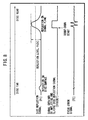
- FIG. 8 shows a PI signal for a dual-layer DVD, where a threshold value is respectively set for the PI signals in both charts as indicated by dotted line in order to effect binary coding of the PI signal corresponding to the recording layer (i.e., PI signal corresponding to reflection on the signal plane).
- the servo processing microcomputer 14 sets this threshold value in relation to the FOK comparator 10.
- the FOK comparator 10 carries out binary coding of the PI signal corresponding to the recording layer based on such threshold value, to thereby generate an FOK signal which keeps the level thereof high during a time period for which the focal point of the laser beam moves across the recording layer as shown in FIGS. 7 and 8, and then send the signal to the servo processing microcomputer 14.
- step S13 the servo processing microcomputer 14 detects a rising edge of the FOK signal, and starts, in synchronization with the rising, count-down of the time set on a timer 18 shown in FIG. 5, where count-up is also allowable, and counting of the number of clock signals at a predetermined frequency in place of time is still also allowable.
- the single-layer/multi-layer determination process then advances to step S 14.
- the disc 1 of single-layer generally gives one cycle of focus error signal within a time period during which the FOK signal is kept at a high level, and two cycles of focus error signal within the time period for the case of the disc 1 of dual-layer. While it may be sufficient to set the time period, during which the FOK signal is kept at a high level as shown in FIGs. 7 and 8, on the timer 18 as a count-down time, the video game console herein is designed to set on the timer 18 a longer time period comprising the foregoing time period for essentially ensuring the high-level of the FOK signal and an additional time period.
- Such longer time setting can successfully suppress variation in moving speed of the objective lens 16 which possibly occurs in the individual devices.
- the focal point of the laser beam is moved under control from the Far position to the Near position at a constant velocity as described in the above.
- Such control of focal movement allows the focal point of the laser beam to move from a first recording layer (Layer0) to a second recording layer (Layer1) in this order, so that focus error signals with large amplitudes will appear each time the focal point of the laser beam moves to the individual recording layers.
- step S14 the servo processing microcomputer 14 detects a peak-to-bottom level difference of the focus error signal obtained when the focal point of the laser beam moves to the first recording layer (Layer0).
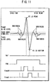
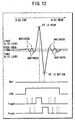
- FIGs. 10 to 12 are the waveform charts individually showing the focus error signal obtained when the focal point of the laser beam moves to the recording layer of a single-layer DVD, the foregoing FOK signal, the FcmpH signal kept at a high level during a period for which the level of the focus error signal is higher than the high-level threshold value (FcmpH slice level) set for such focus error signal, and the FcmpL signal kept at a high level during a period for which the level of the focus error signal becomes lower than the low-level threshold value (FcmpL slice level) set for such focus error signal.
- FIG. 10 is an exemplary waveform chart showing that the levels of the waviness component appearing immediately before and after the main focus error signal fall within a range from the low-level threshold value and the high-level threshold value.
- fake pulse due to waviness component (see pulses indicated by dotted line in FIGs. 11 and 12) is not generated relative to the FcmpH signal and the FcmpL signal.
- FIGs. 11 and 12 are the waveform charts showing that the levels of the waviness component appearing immediately before and after the focus error signal is higher than the high-level threshold value and is lower than the low-level threshold value, where FIG. 12 shows a larger level of the waviness component than that in FIG. 11.
- the FcmpH signal is kept at a high level during a period for which the level of the main focus error signal is higher than the high-level threshold value
- the FcmpL signal is kept at a high level during a period during for which the level of the main focus error signal becomes lower than the low-level threshold value.
- high-level fake pulses appear in association with the FcmpH signal over a period for which the level of the waviness component is higher than the high-level threshold value
- high-level fake pulses appear in association with the FcmpL signal over a period for which the level of the waviness component becomes lower than the low-level threshold value, as indicated by the dotted line in FIGs. 11 and 12.
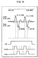
- FIGs. 13 to 15 are the waveform charts individually showing the focus error signal obtained when the focal point of the laser beam moves to the recording layer of a dual-layer DVD, the foregoing FOK signal, the FcmpH signal kept at a high level over a period for which the level of the focus error signal is higher than the high-level threshold value (FcmpH slice level) set for such focus error signal, and the FcmpL signal kept at a high level over a period for which the level of the focus error signal becomes lower than the low-level threshold value (FcmpL slice level) set for such focus error signal.
- FIG. 13 is an exemplary waveform chart showing that the levels of the waviness component appearing immediately before and after the main focus error signal fall within a range from the low-level threshold value and the high-level threshold value.
- fake pulse due to waviness component (see pulses indicated by dotted line in FIGs. 14 and 15) is not generated relative to the FcmpH signal and FcmpL.
- FIGs. 14 and 15 are the waveform charts showing that the levels of the waviness component appearing immediately before and after the focus error signal is higher the high-level threshold value and is also lower than the low-level threshold value, where FIG. 15 shows a larger level of the waviness component than that in FIG. 14.
- the FcmpH signal is kept at a high level over a period for which the level of the main focus error signal exceeds the high-level threshold value
- the FcmpL signal is kept at a high level over a period for which the level of the main focus error signal becomes lower than the low-level threshold value.
- high-level fake pulses appear in association with the FcmpH signal over a period for which the level of the waviness exceeds the high-level threshold value
- high-level fake pulses appear in association with the FcmpL signal over a period for which the level of the waviness becomes lower than the low-level threshold value, as indicated by the dotted line in FIGs. 14 and 15.
- the servo processing microcomputer 14 sets the high-level threshold value (FcmpH Slice Level) for the FcmpH comparator 7 shown in FIG. 5, and sets the low-level threshold value (FcmpL Slice Level) for the FcmpL comparator 8.
- the FcmpH comparator 7 generates the FcmpH signal which is kept at a high level over a period for which the level of the focus error signal fed from the RF amplifier 5 is higher the high-level threshold value (FcmpH Slice Level), and then sends it to the servo processing microcomputer 14.
- the FcmpL comparator 8 generates the FcmpL signal which is kept at a high level over a period for which the level of the focus error signal fed from the RF amplifier 5 is lower than the low-level threshold value (FcmpL Slice Level), and then sends it to the servo processing microcomputer 14.
- the peak bottom detector 6 is supplied with, through the servo processing microcomputer 14, the FcmpH signal and FcmpL signal detected by the comparators 7 and 8, respectively.
- the peak bottom detector 6 detects a value of the focus error signal which grows highest during a period from the rising edge and falling edge of the FcmpH signal, and supplies the signal value as a peak value of the focus error signal to the servo processing microcomputer 14.
- the servo processing microcomputer 14 stores this peak value as a peak value (L0 peak) for the first recording layer.
- the peak bottom detector 6 also detects a value of the focus error signal which grows lowest during a period from the rising edge and falling edge of the FcmpL signal, and supplies the signal value as a bottom value of the focus error signal to the servo processing microcomputer 14.
- the servo processing microcomputer 14 stores this bottom value as a bottom value (L0 bottom) for the first recording layer.
- the servo processing microcomputer 14 Based on such peak value (L0 peak) and bottom value (L0 bottom), the servo processing microcomputer 14 then detects a peak-to-bottom level (L0 Level) of the focus error signal obtained when the focal point of the laser beam lands on the first recording layer (Layer0). This is all about the operation in step S14.
- the servo processing microcomputer 14 makes a determination that a disc unavailable on the video game console (invalid disc) was loaded, and typically displays an error message for the user.
- step S15 the peak bottom detector 6 supplies a value of the focus error signal which was determined as having a highest value during a period since the rising edge to the falling edge of another FcmpH signal next to the foregoing FcmpH signal which has previously been used for detecting L0 Level, as a peak value of such focus error signal to the servo processing microcomputer 14.
- the servo processing microcomputer 14 stores this peak value as a peak value (L1peak) for the second recording layer.
- the peak bottom detector 6 supplies a value of the focus error signal which was determined as having a lowest value during a period since the rising edge to the falling edge of another FcmpL signal next to the foregoing FcmpL signal which has previously been used for detecting L0 Level, as a bottom value of such focus error signal to the servo processing microcomputer 14.
- the servo processing microcomputer 14 stores this bottom value as a bottom value (L1 bottom) for the second recording layer.
- the servo processing microcomputer 14 Based on such peak value (L1 peak) and bottom value (L1 bottom), the servo processing microcomputer 14 then detects a peak-to-bottom level (L1 Level) of the focus error signal obtained when the focal point of the laser beam lands on the second recording layer (Layer1).
- L1 Level peak-to-bottom level
- step S16 the servo processing microcomputer 14 makes determination as explained below based on the L0 Level, L1 Level, a predetermined constant K, Min Level (minimum level) that expresses a level as small as being not realistic as a focus error signal corresponding to the recording layer, and a count value of the timer 18.
- Min Level minimum level
- the "predetermined constant K" herein is determined based on standard reflectivity of the individual recording layers according to a certain disc format, level of the waviness component contained in the focus error signal and so forth.
- the ratio between a peak-to-bottom level of the focus error signal for the first recording layer ranging from the peak (L0 peak and L1 peak) to the bottom (L0 bottom and L1 bottom) and a peak-to-bottom level of the focus error signal for the second recording layer ranging from the peak (L0 peak and L1 peak) to the bottom (L0 bottom and L1 bottom) is assumed as 1:3 at most or below. It is also programmed that a signal having a level equal to or less than 1/3 (approx. 33%) of the focus error signal corresponding to the recording layer is determined, if occurred, as a waviness component.
- FIG. 16 shows a list of criteria for determination made by the servo processing microcomputer 14.
- the servo processing microcomputer 14 makes, as shown in the flow chart in FIG. 9, the single-layer/multi-layer determination process return from step S16 to step S14, from where another process for detecting L0 Level and L1 Level starts again.
- L1 Level larger than the Min Level means that such L1 Level corresponds to the main focus error signal.
- the fact that the ratio obtained by dividing such L1 Level corresponding to the main focus error signal by L0 Level corresponding to the first recording layer is larger than the constant K means that L0 Level is a very small value far from being supposed as the main focus error signal.
- the servo processing microcomputer 14 makes, as shown in the flow chart in FIG. 9, the single-layer/multi-layer determination process advance from step S16 to step S 18.
- step S18 the servo processing microcomputer 14 discards L0 Level corresponding to the first recording layer, which was detected first, and then stores L1 Level corresponding to the second recording layer, which was detected next, as L0 Level corresponding to the first recording layer.
- the single-layer/multi-layer determination process advances to step S15 to thereby make a second trial of L1 Level detection.
- Next case relates to that a ratio (L0 Level/L1 Level) obtained by dividing L0 Level corresponding to the first recording layer by L1 Level corresponding to the second recording layer is larger than the constant K, and that L0 Level is larger than Min Level, and further that the count-down by the timer 18 is still in progress (i.e., within the counting period).
- the servo processing microcomputer 14 in this case issues "Determination C" according to which such L1 Level represents a waviness component.
- L0 Level larger than the Min Level means that such L0 Level has a value corresponding to the main focus error signal.
- the fact that the ratio obtained by dividing such L0 Level corresponding to the main focus error signal by L1 Level corresponding to the second recording layer is larger than the constant K means that L1 Level is a very small value far from being supposed as the main focus error signal.
- the fact that the count-down is still in progress although L1 Level is detected means that such L1 Level corresponds to the fake pulse and that true L1 Level has not been detected yet.
- the servo processing microcomputer 14 issues "Determination C" according to which the single-layer/multi-layer determination process goes from step S16 back to step S15 to thereby make a second trial of L1 Level detection, as shown in FIG. 9.
- Next case relates to that the count-down by the timer 18 has completed (measurement period expired) before the L1 Level corresponding to the second recording layer is detected, and that L0 Level corresponding to the first recording layer is larger than Min Level. This means that the second recording layer is not found on the disc 1, and that already-detected L0 Level corresponding to the first recording layer has a value which corresponds to the main focus error signal.
- the servo processing microcomputer 14 thus issues "Determination "D" according to which the single-layer/multi-layer determination process advances from step S16 to step S17 as shown in the flow chart in FIG. 9, and in which step S17, the disc 1 currently loaded on the video game console is determined as a single-layer DVD (single-layer disc), and the single-layer/multi-layer determination process shown in the flow chart in FIG. 9 comes to the end. This ensures a correct determination of a single-layer DVD having only one recording layer.
- the DVD having one recording layer on each side is a multi-layer storage medium, as two recording layers exist for the whole disc. However, as only one recording layer exists for one side, the DVD having one recording layer on each side is determined as a single-layer DVD in determination process "D.”
- the next case relates to that a ratio (L1 Level/L0 Level) obtained by dividing L1 Level corresponding to the second recording layer by L0 Level corresponding to the first recording layer is smaller than the constant K, and that both of L0 Level and L1 Level are larger than Min Level.
- L0 Level and L1 Level have a similar level, and that both of L0 Level and L1 Level correspond to the main focus error signal since both of them are larger than Min Level.
- the servo processing microcomputer 14 thus issues "Determination E" according to which the single-layer/multi-layer determination process advances from step S16 to step S19 as shown in the flow chart in FIG. 9, and in which step S19, the disc 1 currently loaded on the video game console is determined as a dual-layer DVD (dual-layer disc) having two recording layers, and the single-layer/multi-layer determination process shown in the flow chart in FIG. 9 comes to the end. This ensures a correct determination of a dual-layer DVD having two recording layers.
- the video game console of this embodiment determines whether the recording layer of the disc 1 is of single-layer or multi-layer based on a relative ratio of reproduction outputs (focus error signal in this case) obtained from the individual recording layers. This successfully ensures a wide tolerance for the reproduction output level obtained from the disc 1, and allows correct single-layer/multi-layer determination of discs by properly coping with various discs differing in the reflectivity or with temperature-caused or time-dependent fluctuation in reproduction output level.
- adjustment of various threshold values and so forth of video game console having the single-layer/multi-layer determination function may be omissible at the time of delivery from the works by virtue of its stability against changes in the reproduction output level.
- the single-layer/multi-layer determination is based on amplitude of the reproduction output, correct determination of the number of recording layers on the disc will be ensured even when the reproduction output accidentally has unbalanced amplitude between the former half and latter half of one period.
- the present invention is also applicable to other devices such as DVD player device and DVD recording/reproduction device, and is further applicable to any other devices for handling recording medium for which both of single-layer type and multi-layer type are available.
- the present invention is applicable to a video game console, video game console, DVD device, magneto-optical disc device, magnetic disc device, and the like, capable of reproducing a recording medium having one, tow or more recording layers (e.g., optical disc).
- a recording medium having one, tow or more recording layers (e.g., optical disc).
Landscapes
- Optical Recording Or Reproduction (AREA)
Abstract
Description
Claims (11)
- A device for determining type of a recording medium, comprising:scanning period setting means for setting a scanning period during which a recording medium is scanned perpendicular to a recording surface thereof;level detection means for detecting a reproduction output level based on an amplitude of a reproduction output in the scanning period;counting means for counting the number of reproduction outputs having the reproduction output level higher than a predetermined level, out of reproduction outputs in the scanning period; anddetermination means for determining that the recording medium has recording layers of the same number as that of the reproduction outputs counted by the counting means.
- The device according to Claim 1, further comprising:storage means having stored therein a normal ratio of a plurality of reproduction outputs at a normal level obtained from a recording medium having a plurality of recording layers, whereinfrom the recording medium at least a first reproduction output and a second reproduction output are obtained; andthe counting means divides a value of the second reproduction output by a value of the first reproduction output, compares the result of division with the normal ratio stored in the storage means, and when the result of division is larger than the normal ratio, then compares the level of the second reproduction output with the predetermined level.
- The device according to Claim 1 or 2, wherein the reproduction output level is a difference between a peak level and a bottom level of the reproduction output.
- The device according to Claim 1, 2 or 3, wherein the reproduction output is a focus error signal.
- The device according to any one of Claims 1 to 4, wherein the scanning period setting means sets, as the scanning period, a period for which reproduction outputs corresponding to the recording layer of the recording medium are obtained.
- A method for determining type of a recording medium, comprising the steps of:setting a scanning period during which a recording medium is scanned perpendicular to a recording surface thereof;detecting a reproduction output level based on an amplitude of a reproduction output in the scanning period;counting the number of reproduction outputs having the reproduction output level higher than a predetermined level, out of reproduction outputs in the scanning period; anddetermining that the recording medium has recording layers of the same number as that of the counted reproduction outputs.
- The method according to Claim 6, further comprising the steps of:storing a normal ratio of a plurality of reproduction outputs at a normal level obtained from a recording medium having a plurality of recording layers,obtaining at least a first reproduction output and a second reproduction output from the recording medium;dividing a value of the second reproduction output by a value of the first reproduction output;comparing the result of division with the normal ratio; andcomparing the level of the second reproduction output with the predetermined level when the result of division is larger than the normal ratio.
- A computer-readable recording medium having recorded therein a program to be executed by a computer for determining type of a recording medium, wherein the program comprises the steps of:setting a scanning period during which a recording medium is scanned perpendicular to a recording surface thereof;detecting a reproduction output level based on an amplitude of a reproduction output in the scanning period;detecting the number of reproduction outputs having the reproduction output level higher than a predetermined level, out of reproduction outputs; anddetermining that the recording medium has recording layers of the same number as that of the detected reproduction outputs.
- The computer-readable recording medium according to Claim 8, wherein the program further comprises the steps of:storing a normal ratio of a plurality of reproduction outputs at a normal level obtained from a recording medium having a plurality of recording layers,obtaining at least a first reproduction output and a second reproduction output from the recording medium;dividing a value of the second reproduction output by a value of the first reproduction output;comparing the result of division with the normal ratio; andcomparing the level of the second reproduction output with the predetermined level when the result of division is larger than the normal ratio.
- A program to be executed by a computer for determining type of recording media, comprising the steps of:setting a scanning period during which a recording medium is scanned perpendicular to a recording surface thereof;detecting a reproduction output level based on an amplitude of a reproduction output in the scanning period;counting the number of reproduction outputs having the reproduction output level higher than a predetermined level, out of reproduction outputs in the scanning period; anddetermining that the recording medium has recording layers of the same number as that of the counted reproduction outputs.
- The program according to Claim 10, further comprising the steps of:storing a normal ratio of a plurality of reproduction outputs at a normal level obtained from a recording medium having a plurality of recording layers,obtaining at least a first reproduction output and a second reproduction output from the recording medium;dividing a value of the second reproduction output by a value of the first reproduction output;comparing the result of division with the normal ratio; andcomparing the level of the second reproduction output with the predetermined level when the result of division is larger than the normal ratio.
Applications Claiming Priority (3)
| Application Number | Priority Date | Filing Date | Title |
|---|---|---|---|
| JP2001322907 | 2001-10-19 | ||
| JP2001322907 | 2001-10-19 | ||
| PCT/JP2002/010736 WO2003036628A1 (en) | 2001-10-19 | 2002-10-16 | Storage medium type identifying method |
Publications (3)
| Publication Number | Publication Date |
|---|---|
| EP1437716A1 true EP1437716A1 (en) | 2004-07-14 |
| EP1437716A4 EP1437716A4 (en) | 2006-12-20 |
| EP1437716B1 EP1437716B1 (en) | 2010-07-14 |
Family
ID=19139873
Family Applications (1)
| Application Number | Title | Priority Date | Filing Date |
|---|---|---|---|
| EP02802016A Expired - Lifetime EP1437716B1 (en) | 2001-10-19 | 2002-10-16 | Storage medium type identifying method |
Country Status (4)
| Country | Link |
|---|---|
| US (1) | US7193945B2 (en) |
| EP (1) | EP1437716B1 (en) |
| DE (1) | DE60237024D1 (en) |
| WO (1) | WO2003036628A1 (en) |
Families Citing this family (9)
| Publication number | Priority date | Publication date | Assignee | Title |
|---|---|---|---|---|
| JP2003248940A (en) * | 2002-02-21 | 2003-09-05 | Funai Electric Co Ltd | Optical disc device |
| JP4380438B2 (en) * | 2004-07-13 | 2009-12-09 | ソニー株式会社 | Optical disk device |
| JP2006236469A (en) * | 2005-02-24 | 2006-09-07 | Canon Inc | Optical information recording / reproducing apparatus |
| JP4193829B2 (en) * | 2005-08-22 | 2008-12-10 | 船井電機株式会社 | Disk unit |
| JP4197526B2 (en) * | 2006-07-26 | 2008-12-17 | 株式会社ソニー・コンピュータエンタテインメント | Optical disc apparatus, control method thereof, and program |
| JP4272222B2 (en) * | 2006-07-28 | 2009-06-03 | 株式会社ソニー・コンピュータエンタテインメント | Optical disc apparatus, control method thereof, and program |
| KR20080058891A (en) * | 2006-12-22 | 2008-06-26 | 삼성전자주식회사 | Optical information storage medium discrimination method and apparatus |
| KR20080064617A (en) * | 2007-01-05 | 2008-07-09 | 삼성전자주식회사 | Optical information storage medium discrimination method and apparatus |
| JP4400661B2 (en) * | 2007-09-04 | 2010-01-20 | 船井電機株式会社 | Optical disk device |
Family Cites Families (17)
| Publication number | Priority date | Publication date | Assignee | Title |
|---|---|---|---|---|
| JPS6231031A (en) | 1985-08-01 | 1987-02-10 | Canon Inc | Focus servo leading-in device of information recording device |
| JP2630043B2 (en) | 1990-09-13 | 1997-07-16 | 日本電気株式会社 | Optical recording / reproducing device |
| JP3328652B2 (en) * | 1991-08-28 | 2002-09-30 | 松下電器産業株式会社 | Optical recording / reproducing method |
| CN1075222C (en) * | 1995-07-27 | 2001-11-21 | 松下电器产业株式会社 | CD device |
| JPH09259435A (en) | 1996-03-22 | 1997-10-03 | Seiko Epson Corp | Optical recording medium processing method and optical recording device |
| KR100197623B1 (en) * | 1996-10-24 | 1999-06-15 | 윤종용 | Disc type discrimination method and DVD system using the same |
| JPH10199003A (en) * | 1997-01-10 | 1998-07-31 | Sony Corp | Optical disk drive |
| JP3671572B2 (en) * | 1997-01-10 | 2005-07-13 | ソニー株式会社 | Optical disk device |
| WO1998031012A1 (en) * | 1997-01-10 | 1998-07-16 | Sony Corporation | Optical disk device and method for discriminating optical disk |
| JP3148683B2 (en) | 1997-03-10 | 2001-03-19 | 三洋電機株式会社 | Disk discriminating method and apparatus |
| JPH1166712A (en) * | 1997-08-26 | 1999-03-09 | Sanyo Electric Co Ltd | Disk discriminating method |
| JPH11288550A (en) | 1998-03-31 | 1999-10-19 | Matsushita Electric Ind Co Ltd | Optical disc identification method and optical disc apparatus |
| JPH11353785A (en) | 1998-06-03 | 1999-12-24 | Sony Corp | Optical disc discriminating apparatus and discriminating method |
| JPH11353787A (en) | 1998-06-11 | 1999-12-24 | Matsushita Electric Ind Co Ltd | Method and apparatus for discriminating the number of optical disc layers |
| JP2000228049A (en) | 1999-02-04 | 2000-08-15 | Mitsubishi Electric Corp | Disc discriminating device in optical disc device |
| JP2001319344A (en) * | 2000-03-03 | 2001-11-16 | Sony Computer Entertainment Inc | Focus controller, recording medium and optical disk reproducing device |
| JP4067781B2 (en) * | 2001-04-13 | 2008-03-26 | 株式会社日立エルジーデータストレージ | Disc player |
-
2002
- 2002-10-16 EP EP02802016A patent/EP1437716B1/en not_active Expired - Lifetime
- 2002-10-16 DE DE60237024T patent/DE60237024D1/en not_active Expired - Lifetime
- 2002-10-16 WO PCT/JP2002/010736 patent/WO2003036628A1/en not_active Ceased
- 2002-10-17 US US10/273,383 patent/US7193945B2/en not_active Expired - Lifetime
Also Published As
| Publication number | Publication date |
|---|---|
| EP1437716B1 (en) | 2010-07-14 |
| DE60237024D1 (en) | 2010-08-26 |
| US20030086347A1 (en) | 2003-05-08 |
| US7193945B2 (en) | 2007-03-20 |
| WO2003036628A1 (en) | 2003-05-01 |
| EP1437716A4 (en) | 2006-12-20 |
Similar Documents
| Publication | Publication Date | Title |
|---|---|---|
| KR100529809B1 (en) | Method and device for calibrating an optical disc system | |
| US5724325A (en) | Method for reducing lead in time in an optical disk recording or reproducing apparatus capable of processing data for multiple types of disks | |
| KR100508192B1 (en) | Apparatus and method for determining disc type before playing data from a disc | |
| EP1437716B1 (en) | Storage medium type identifying method | |
| KR19980033268A (en) | Disk recording and / or reproducing apparatus and recording and / or reproducing method thereof | |
| US6556302B2 (en) | Apparatus for and method of determining information record medium | |
| JPH11149640A (en) | Optical disk drive | |
| US20040013066A1 (en) | Unbalance disc detection apparatus and unbalance disc detection method | |
| US20060139803A1 (en) | Multilayer information medium, reproduction method and reproduction device thereof | |
| WO2008093928A1 (en) | Method and apparatus for controlling focus of an optical information storage medium | |
| US6449222B2 (en) | Servo control apparatus and method utilizing a light spot shifted beyond a signal change area of an information record medium | |
| US7385895B2 (en) | Method of discriminating optical disc type and apparatus thereof | |
| JPH1139785A (en) | Mass eccentric disk detecting method for disk player | |
| JP4393289B2 (en) | Focus error signal authenticity determination device, focus error signal authenticity determination program, storage medium storing focus error signal authenticity determination program, focus error signal authenticity determination method, storage medium type determination program, storage Medium type determination device, storage medium storing storage medium type determination program, and storage medium type determination method | |
| KR100555487B1 (en) | Determination of Playback Speed Based on Deflection Vibration of Optical Disc | |
| JP2003196847A (en) | Program and device for deciding kind of storage medium, storage medium stored with kind deciding program for storage medium, and kind deciding method for storage medium | |
| US8331213B2 (en) | Information recording medium, information reproducing device and method, and apparatus and method for manufacturing information recording medium | |
| JP4218596B2 (en) | Optical disk device | |
| US20080285411A1 (en) | Optical disk drive | |
| KR19990080062A (en) | How to move the target position in search mode of optical pickup | |
| JPH09259513A (en) | Optical disc detection method in optical disc device | |
| KR100734102B1 (en) | Tracking Servo Adjustment of Optical Disc Device | |
| KR100275875B1 (en) | Track Jump Control Method in Defect | |
| JP2002298388A (en) | Optical device and optical reader for recorded information | |
| JPH09120628A (en) | Optical disc detection method in optical disc device |
Legal Events
| Date | Code | Title | Description |
|---|---|---|---|
| PUAI | Public reference made under article 153(3) epc to a published international application that has entered the european phase |
Free format text: ORIGINAL CODE: 0009012 |
|
| 17P | Request for examination filed |
Effective date: 20040420 |
|
| AK | Designated contracting states |
Kind code of ref document: A1 Designated state(s): AT BE BG CH CY CZ DE DK EE ES FI FR GB GR IE IT LI LU MC NL PT SE SK TR |
|
| A4 | Supplementary search report drawn up and despatched |
Effective date: 20061122 |
|
| RIC1 | Information provided on ipc code assigned before grant |
Ipc: G11B 7/085 20060101ALI20061116BHEP Ipc: G11B 19/12 20060101AFI20061116BHEP |
|
| 17Q | First examination report despatched |
Effective date: 20080218 |
|
| GRAP | Despatch of communication of intention to grant a patent |
Free format text: ORIGINAL CODE: EPIDOSNIGR1 |
|
| GRAS | Grant fee paid |
Free format text: ORIGINAL CODE: EPIDOSNIGR3 |
|
| GRAA | (expected) grant |
Free format text: ORIGINAL CODE: 0009210 |
|
| AK | Designated contracting states |
Kind code of ref document: B1 Designated state(s): DE FR GB |
|
| REG | Reference to a national code |
Ref country code: GB Ref legal event code: FG4D |
|
| REF | Corresponds to: |
Ref document number: 60237024 Country of ref document: DE Date of ref document: 20100826 Kind code of ref document: P |
|
| PLBE | No opposition filed within time limit |
Free format text: ORIGINAL CODE: 0009261 |
|
| STAA | Information on the status of an ep patent application or granted ep patent |
Free format text: STATUS: NO OPPOSITION FILED WITHIN TIME LIMIT |
|
| 26N | No opposition filed |
Effective date: 20110415 |
|
| REG | Reference to a national code |
Ref country code: DE Ref legal event code: R097 Ref document number: 60237024 Country of ref document: DE Effective date: 20110415 |
|
| REG | Reference to a national code |
Ref country code: FR Ref legal event code: PLFP Year of fee payment: 15 |
|
| REG | Reference to a national code |
Ref country code: FR Ref legal event code: PLFP Year of fee payment: 16 |
|
| REG | Reference to a national code |
Ref country code: FR Ref legal event code: PLFP Year of fee payment: 17 |
|
| PGFP | Annual fee paid to national office [announced via postgrant information from national office to epo] |
Ref country code: FR Payment date: 20210913 Year of fee payment: 20 |
|
| PGFP | Annual fee paid to national office [announced via postgrant information from national office to epo] |
Ref country code: GB Payment date: 20210907 Year of fee payment: 20 |
|
| PGFP | Annual fee paid to national office [announced via postgrant information from national office to epo] |
Ref country code: DE Payment date: 20210908 Year of fee payment: 20 |
|
| REG | Reference to a national code |
Ref country code: DE Ref legal event code: R071 Ref document number: 60237024 Country of ref document: DE |
|
| REG | Reference to a national code |
Ref country code: GB Ref legal event code: PE20 Expiry date: 20221015 |
|
| PG25 | Lapsed in a contracting state [announced via postgrant information from national office to epo] |
Ref country code: GB Free format text: LAPSE BECAUSE OF EXPIRATION OF PROTECTION Effective date: 20221015 |