EP1437579A2 - Liquid level measurement using a float attached to a rotating arm - Google Patents
Liquid level measurement using a float attached to a rotating arm Download PDFInfo
- Publication number
- EP1437579A2 EP1437579A2 EP03029644A EP03029644A EP1437579A2 EP 1437579 A2 EP1437579 A2 EP 1437579A2 EP 03029644 A EP03029644 A EP 03029644A EP 03029644 A EP03029644 A EP 03029644A EP 1437579 A2 EP1437579 A2 EP 1437579A2
- Authority
- EP
- European Patent Office
- Prior art keywords
- displacement
- tank
- float
- fuel
- sensor
- Prior art date
- Legal status (The legal status is an assumption and is not a legal conclusion. Google has not performed a legal analysis and makes no representation as to the accuracy of the status listed.)
- Withdrawn
Links
Images


Classifications
-
- G—PHYSICS
- G01—MEASURING; TESTING
- G01F—MEASURING VOLUME, VOLUME FLOW, MASS FLOW OR LIQUID LEVEL; METERING BY VOLUME
- G01F23/00—Indicating or measuring liquid level or level of fluent solid material, e.g. indicating in terms of volume or indicating by means of an alarm
- G01F23/30—Indicating or measuring liquid level or level of fluent solid material, e.g. indicating in terms of volume or indicating by means of an alarm by floats
- G01F23/32—Indicating or measuring liquid level or level of fluent solid material, e.g. indicating in terms of volume or indicating by means of an alarm by floats using rotatable arms or other pivotable transmission elements
- G01F23/36—Indicating or measuring liquid level or level of fluent solid material, e.g. indicating in terms of volume or indicating by means of an alarm by floats using rotatable arms or other pivotable transmission elements using electrically actuated indicating means
Definitions
- the present invention relates to a system for detecting the remaining amount of liquid in a tank, which is suitably used, for example, in detecting the remaining amount of fuel accumulated in an automotive fuel tank.
- the fuel tank mounted on the vehicle is provided with a float-type level detecting system, for example, to detect the remaining amount of fuel accumulated in the tank.
- the float-type level detecting system comprises essentially a float arranged vertically movably with the level of fuel accumulated in the fuel tank, a sensor part fixedly arranged in the tank and for sensing a fuel level position in accordance with displacement of the float, and a displacement transmitting part comprising an arm for transmitting displacement of the float to the sensor part.
- the float moves vertically with the fuel level, which is transmitted to the sensor part where the fuel remaining amount in the tank is detected in accordance with a fuel level position.
- the typical level detecting system is constructed to detect the fuel remaining amount through the sensor part fixedly mounted to the top face of the fuel tank, to which displacement of the float moving vertically with the level of fuel in the fuel tank is directly transmitted through the arm.
- the level of fuel in the fuel tank is displaced vertically accordingly. Then, the above level detecting system detects and outputs the fuel remaining amount including this level displacement as variations in the fuel remaining amount, which is different from the actual fuel remaining amount, leading to impossibility of stable detection of the correct fuel remaining amount.
- an object of the present invention to provide a system for detecting the remaining amount of liquid in a tank, which allows continuous and stable detection of the remaining amount of liquid in the tank, and thus enhancement in the reliability of the system.
- the present invention provides generally a system for detecting a remaining amount of liquid in a tank, which comprises: a float which produces a displacement with a level of liquid; a sensor part mounted to the tank at a position above a bottom thereof, the sensor part sensing the remaining amount of liquid in accordance with the displacement of the float; and a displacement transmitting part which transmits the displacement of the float to the sensor part, the displacement transmitting part comprising a support member mounted to the bottom of the tank, an arm having a base end mounted to the support member and a front end mounted to the float, and a link mechanism which couples the sensor part and the base end of the arm.
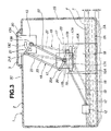
- FIG. 1 is a longitudinal sectional view showing a first embodiment of a system for detecting the remaining amount of liquid in a tank according to the present invention
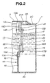
- FIG. 2 is a sectional view taken along the line II-II in FIG. 1;
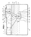
- FIG. 3 is a view similar to FIG. 1, showing operation of the system in FIG. 1;
- FIG. 4 is a view similar to FIG. 3, showing a second embodiment of the present invention.
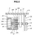
- FIG. 5 is a view similar to FIG. 2, taken along the line V-V in FIG. 4;
- FIG. 6 is a fragmentary enlarged sectional view showing a variation of the first embodiment.
- a fuel tank 1 to be mounted on the vehicle comprises a main body 2 made from a light flexible material such as synthetic resin, and a cover plate 3 as will be described later.
- Fuel tank 1 comprises a mounting flange, not shown, provided to a top face 2C, an upper portion of a side face 2B, or the like of tank main body 2 as will be described later, through the use of which fuel tank 1 is fixed to a frame and the like of the vehicle.
- tank main body 2 comprises a bottom face 2A, side face 2B extending upward to surround bottom face 2A, top face 2C integrally formed with the upper end of side face 2B to conceal side face 2B from above, an opening 2D formed roughly in the center of top face 2C, and the like.
- a fuel remaining-amount detecting system 11 as will be described later is inserted into tank main body through opening 2D.
- Cover plate 3 which constitutes fuel tank 1 together with tank main body 2, is made from substantially the same resin material as that of tank main body 2. Cover plate 3 serves to close opening 2D of tank main body 2 from above. A rotation-angle sensor 13 as will be described later is fixed on the underside of cover plate 3 facing the inside of tank main body 2.
- Fuel remaining-amount detecting system 11 which forms a system for detecting the remaining amount of liquid in the embodiment, serves to detect the remaining amount of a fuel F accumulated in fuel tank 1.
- System 11 comprises a float 12 as will be described later, rotation-angle sensor 13, a displacement transmitting part 14, and the like.
- Float 12 is mounted at the front end of an arm 18 as will be described later, and moves vertically with the level of fuel F accumulated in fuel tank 1.
- Rotation-angle sensor or sensor part 13 is fixedly arranged in fuel tank 1 above bottom face 2A, and serves to sense the angle of rotation electrically, magnetically, or optically.
- rotation-angle sensor 13 comprises essentially a base plate 13A fixed on the underside of cover plate 3, a rotation shaft 13B rotatably mounted to base plate 13A, a resistor 13C circularly formed about rotation shaft 13B, and a conductive slider 13D fixed to a second lever 21 as will be described later to make slide contact with resistor 13C.
- Displacement of float 12 is transmitted through second lever 21 and the like to slider 13D, which moves on resistor 13C in a sliding way, obtaining a change in a value of resistance of resistor 13C in accordance with displacement of float 12.
- Rotation-angle sensor 13 senses a level position or remaining amount of fuel F in accordance with a value of resistance of resistor 13C.
- Displacement transmitting part 14 serves to transmit displacement of float 12 to rotation-angle sensor 13, and comprises a bracket 15 as will be described later, arm 18, a link mechanism 19, and the like.
- Bracket or support member 15 is arranged on bottom face 2A of tank main body 2, and comprises a stationary portion or stationary support portion 16 fixedly mounted to bottom face 2A and a movable portion or movable support portion 17 movably mounted to stationary portion 16.
- Stationary bracket portion 16 is shaped like a rectangular plate, and is arranged to extend upward from bottom face 2A of tank main body 2.
- a slot 16A is formed in the upper end of stationary bracket portion 16 to extend horizontally in parallel to bottom face 2A.
- movable bracket portion 17 is shaped like a rectangular plate smaller than that of stationary bracket portion 16, and has a lower end having two guide pins 17A protruding therefrom. Movable bracket portion 17 is slidably engaged in slot 16A of stationary bracket portion 16, and can move horizontally while being guided therein.
- a pin 17B is arranged in the center of movable bracket portion 17 to protrude in the direction opposite to stationary bracket portion 16.
- Arm 18 has a base end 18A rotatably supported by pin 17B of movable bracket portion 17, and a front end or free end 18B mounted to float 12.
- a first lever 20 as will be described later is integrated with base end 18A of arm 18.
- Link mechanism 19 is arranged between rotation-angle sensor 13 and base end 18A of arm 18, and include a parallel link comprising first lever 20, a second lever 21, a first rod 22, a second rod 23, and the like as will be described later.
- Link mechanism 19 serves to transmit displacement of float 12 which moves with the level of fuel F to rotation-angle sensor 13 through arm 18.
- First lever 20 is integrated with base end 18A of arm 18, and forms a given angle with arm 18. First lever 20 rotates, together with arm 18, about pin 17B of movable bracket portion 17. A pin 20A is protrusively arranged at the front end of first lever 20.
- Second lever 21 is fixedly mounted to rotation shaft 13B of rotation-angle sensor 13, and has substantially the same length as that of first lever 20. As shown in FIG. 2, slider 13D is fixed to second lever 21 in a portion facing resistor 13C of rotation-angle sensor 13. A pin 21 A is protrusively arranged at the front end of second lever 21.
- First rod 22 is arranged between rotation shaft 13B of rotation-angle sensor 13 and pin 17B of movable bracket portion 17, and has one end rotatably mounted to rotation shaft 13 and another end rotatably mounted to pin 17B.
- Second rod 23 is arranged between first lever 20 and second lever 21, and has substantially the same length as that of first lever 22.
- Second lever 23 has one end rotatably mounted to pin 20A of first lever 20 and another end rotatably mounted to pin 21 A of second lever 21.
- fuel F accumulated in fuel tank 1 is discharged to the outside of fuel tank 1 for supply to an automotive engine, for example.
- Fuel F in fuel tank 1 reduces gradually in accordance with consumption in the engine, having the level lowering accordingly.
- link mechanism 19 includes a parallel link
- second lever 21 coupled to first lever 20 through second rod 23 rotates in the direction of arrow B by the same angle of rotation as that of first lever 20 about rotation shaft 13B of rotation-angle sensor 13.
- slider 13D fixed to second lever 21 moves on resistor 13C of rotation-angle sensor 13 in a sliding way.
- rotation-angle sensor 13 can sense a level position of fuel F in accordance with a value of resistance of resistor 13C, from which the remaining amount of fuel F accumulated in fuel tank 1 can be determined.
- link mechanism 19 includes a parallel link
- second lever 21 constituting link mechanism 19 holds the position shown by solid line in FIG. 3, i.e. position before displacement of bottom face 2A, regardless of displacement of first lever 20, first rod 22, and second rod 23.
- slider 13D fixed to second lever 21 does not move on resistor 13C of rotation-angle sensor 13, allowing a resistance of resistor 13 to be held at a given value.
- bracket 15 is arranged on bottom face 2A of fuel tank 1, and base end 18A of arm 18 having float 12 at front end 18B is rotatably mounted to pin 17B of movable bracket portion 17 which constitutes bracket 15. And base end 18A of arm 18 and rotation-angle sensor 13 are coupled by link mechanism 19.
- FIGS. 4 and 5 there is shown second embodiment of the present invention which is substantially the same as the first embodiment except that a sensor casing hermetically isolated from fuel is arranged in the fuel tank to accommodate therein a sensor part.
- a fuel remaining-amount detecting system 31 is arranged in fuel tank 1, and has roughly the same structure as that of fuel remaining-amount detecting system 11 in the first embodiment, comprising float 12, displacement transmitting part 14, a sensor casing 32, a rotation-angle sensor 33 as will be described later, and the like.
- Sensor casing 32 is arranged in fuel tank 1 and fixed on the under face of cover plate 3. As shown in FIG. 5, sensor casing 32 is formed as a box hermetically isolated from fuel F in fuel tank 1 to accommodate therein rotation-angle sensor 33. A bottomed concave cylindrical portion 32A is formed in the side face of sensor casing 32 to protrude inward of sensor casing 32.
- Rotation-angle sensor or sensor part 33 is disposed in sensor casing 32, and comprises a rotation shaft 33A to which displacement of float 12 is transmitted through a shaft 35, a magnet coupling 36 as will be described later, and the like.
- Rotation-angle sensor 33 serves to electrically or magnetically sense, for example, the angle of rotation of rotation shaft 33A through the use of a detection element, not shown, in accordance with which a level position of fuel F, i.e. the remaining amount of fuel F in fuel tank 1 is determined.
- a shaft support plate 34 is fixed on the underside of cover plate 3 to face concave cylindrical portion 32A of sensor casing 32.
- An axially middle portion of shaft 35 is rotatably supported at the lower end of shaft support plate 34.
- Shaft 35 has one end to which second lever 21 constituting link mechanism 19 is fixed and first rod 22 is mounted rotatably, and another end extending into concave cylindrical portion 32A of sensor casing 32.
- Magnet coupling or non-contact coupling 36 is arranged between rotation shaft 33A of rotation-angle sensor 33 and another end of shaft 35, and comprises a female portion 37 fixed to rotation shaft 33A of rotation-angle sensor 33 and a male portion 38 fixed to another end of shaft 35.
- Magnet coupling 36 serves to transmit rotation of shaft 35 to rotation shaft 33A of rotation-angle sensor 33 in a non-contact way with concave cylindrical portion 32A of sensor casing 32 held between female and male coupling portions 37, 38.
- Female coupling portion 37 comprises a magnet mounting cylinder 37A formed like a lidded cylinder to surround concave cylindrical portion 32A of sensor casing 32 and fixed to rotation shaft 33A, and an outer magnet 37B having S and N poles circumferentially alternately disposed on the inner peripheral surface of magnet mounting cylinder 37A.
- male coupling portion 38 comprises a magnet mounting cylinder 38A located at the inner periphery of concave cylindrical portion 32A of sensor casing 32 and engaged on another end of shaft 35, and an inner magnet 38B having S and N poles circumferentially alternately disposed on the outer peripheral surface of magnet mounting cylinder 38A.
- Fuel remaining-amount detecting system 31 Operation of fuel remaining-amount detecting system 31 is fundamentally the same as that of fuel remaining-amount detecting system 11 described in the first embodiment.
- rotation-angle sensor 3 for sensing the remaining amount of fuel F in fuel tank 1 is disposed in sensor casing 32 hermetically isolated from fuel F in fuel tank 1. And rotation shaft 33A of rotation-angle sensor 3 and second lever 21 of link mechanism 19 are coupled through non-contact coupling 36.
- sensor casing 32 can surely prevent fuel F from adhering to rotation-angle sensor 33. With this, corrosion of rotation-angle sensor 33 due to adhesion of fuel F can be restraint, allowing rotation-angle sensor 33 to carry out accurate detection of the remaining amount of fuel F over the long term.
- rotation-angle sensor 33 is fixed to top face 2C of fuel tank 1 through cover plate 3.
- rotation-angle sensor 13 may be fixed to side face 2B of fuel tank 1.
- a sensor support plate 41 fixed to side face 2B of fuel tank 1, through which rotation-angle sensor 13 is fixed to side face 2B.
- sensor casing 32 is disposed in fuel tank 1.
- the sensor casing may be arranged outside fuel tank 1 wherein rotation-angle sensor 13 disposed in the sensor casing and link mechanism 19 are coupled through non-contact coupling 36.
- magnet coupling 36 is adopted to transmit rotation of shaft 35 to rotation shaft 33A of rotation-angle sensor 33.
- other means such as Hall element may be applied to that end.
- first rod 22 constituting link mechanism 19 is connected to rotation shaft 13B of rotation-angle sensor 13 and pin 17B of movable bracket portion 17.
- first rod 22 may be connected to a pin provided to any member other than rotation shaft 13B and a pin provided to any member other than movable bracket portion 17.
- movable bracket portion 17 is movably mounted to stationary bracket portion 16.
- movable bracket portion 17 may be mounted to other member arranged in fuel tank 1, the inner surface of tank main body 2, or the like.
- rotation shaft 13B rotatably mounted to base plate 13A of rotation-angle sensor 13 is rotation shaft 13B, to which second lever 21 constituting link mechanism 19 is fixed.
- rotation shaft 13B there may be arranged a shaft fixedly mounted to base plate 13A, to which second lever 21 is mounted rotatably.
- pin 17B is protrusively provided to movable bracket portion 17 so as to rotatably support base end 18A of arm 18.
- a separate and distinct pin from movable bracket portion 17 may be adopted to couple movable bracket portion 17 and base end 18A of arm 18. The same can be applied to pin 20A of first lever 20 and pin 21 A of second lever 21.
- the present invention is applied to the system for detecting the remaining amount of fuel F accumulated in fuel tank 1.
- the present invention can be applied to systems for detecting the remaining amount of liquid accumulated in a tank, such as working fluid, chemical agent, or the like.
Abstract
Description
Claims (10)
- A system for detecting a remaining amount of liquid in a tank, comprising:a float which produces a displacement with a level of liquid;a sensor part mounted to the tank at a position above a bottom thereof, the sensor part sensing the remaining amount of liquid in accordance with the displacement of the float; anda displacement transmitting part which transmits the displacement of the float to the sensor part, the displacement transmitting part comprising a support member mounted to the bottom of the tank, an arm having a base end mounted to the support member and a front end mounted to the float, and a link mechanism which couples the sensor part and the base end of the arm.
- The system as claimed in claim 1, wherein the link mechanism serves to cancel the displacement of the float resulting from a vertical displacement of the bottom of the tank.
- The system as claimed in claim 1, wherein the support member of the displacement transmitting part comprises a stationary portion mounted to the bottom of the tank and a movable portion mounted to the base end of the arm.
- The system as claimed in claim 3, wherein the movable portion is horizontally movably mounted to the stationary portion.
- The system as claimed in claim 1, wherein the link mechanism comprises a parallel link.
- The system as claimed in claim 1, further comprising a sensor casing provided to the tank, the sensor casing accommodating the sensor part.
- The system as claimed in claim 6, wherein the sensor casing is arranged in the tank to hermetically be isolated from liquid therein.
- The system as claimed in claim 6, further comprising a non-contact coupling for coupling the link mechanism and the sensor part in the sensor casing.
- A system for detecting a remaining amount of liquid in a tank, comprising:a float which produces a displacement with a level of liquid;a sensor part mounted to the tank at a position above a bottom thereof, the sensor part sensing the remaining amount of liquid in accordance with the displacement of the float;a displacement transmitting part which transmits the displacement of the float to the sensor part, the displacement transmitting part comprising a support member mounted to the bottom of the tank, an arm having a base end mounted to the support member and a front end mounted to the float, and a link mechanism which couples the sensor part and the base end of the arm, the link mechanism canceling the displacement of the float resulting from a vertical displacement of the bottom of the tank;a sensor casing arranged in the tank to hermetically be isolated from liquid therein, the sensor casing accommodating the sensor part; anda non-contact coupling which couples the link mechanism and the sensor part in the sensor casing.
- An arrangement, comprising:a tank having a remaining amount of liquid:a float which produces a displacement with a level of liquid;a sensor part mounted to the tank at a position above a bottom thereof, the sensor part sensing the remaining amount of liquid in accordance with the displacement of the float; anda displacement transmitting part which transmits the displacement of the float to the sensor part, the displacement transmitting part comprising a support member mounted to the bottom of the tank, an arm having a base end mounted to the support member and a front end mounted to the float, and a link mechanism which couples the sensor part and the base end of the arm, the link mechanism canceling the displacement of the float resulting from a vertical displacement of the bottom of the tank.
Applications Claiming Priority (2)
| Application Number | Priority Date | Filing Date | Title |
|---|---|---|---|
| JP2003001324A JP2004212286A (en) | 2003-01-07 | 2003-01-07 | Apparatus for detecting remaining amount of liquid in tank |
| JP2003001324 | 2003-01-07 |
Publications (2)
| Publication Number | Publication Date |
|---|---|
| EP1437579A2 true EP1437579A2 (en) | 2004-07-14 |
| EP1437579A3 EP1437579A3 (en) | 2005-10-05 |
Family
ID=32501192
Family Applications (1)
| Application Number | Title | Priority Date | Filing Date |
|---|---|---|---|
| EP03029644A Withdrawn EP1437579A3 (en) | 2003-01-07 | 2003-12-22 | Liquid level measurement using a float attached to a rotating arm |
Country Status (4)
| Country | Link |
|---|---|
| US (1) | US6857314B2 (en) |
| EP (1) | EP1437579A3 (en) |
| JP (1) | JP2004212286A (en) |
| CN (1) | CN1521037A (en) |
Cited By (1)
| Publication number | Priority date | Publication date | Assignee | Title |
|---|---|---|---|---|
| EP2437036A1 (en) * | 2010-09-13 | 2012-04-04 | Audi AG | Measuring device and method for determining a fluid level in a fuel tank |
Families Citing this family (20)
| Publication number | Priority date | Publication date | Assignee | Title |
|---|---|---|---|---|
| JP4165422B2 (en) * | 2004-03-16 | 2008-10-15 | 株式会社デンソー | Liquid level detector |
| WO2009039290A2 (en) | 2007-09-20 | 2009-03-26 | Bradley Fixtures Corporation | Lavatory system |
| JP2011006130A (en) * | 2009-06-29 | 2011-01-13 | Tokiko Techno Kk | Liquid level detector for tanks |
| WO2011044247A1 (en) | 2009-10-07 | 2011-04-14 | Bradley Fixtures Corporation | Lavatory system with hand dryer |
| KR101800018B1 (en) | 2011-02-17 | 2017-11-22 | 르노삼성자동차 주식회사 | Apparatus for measuring amount of fuel |
| US9758953B2 (en) | 2012-03-21 | 2017-09-12 | Bradley Fixtures Corporation | Basin and hand drying system |
| US9267736B2 (en) | 2011-04-18 | 2016-02-23 | Bradley Fixtures Corporation | Hand dryer with point of ingress dependent air delay and filter sensor |
| US9170148B2 (en) | 2011-04-18 | 2015-10-27 | Bradley Fixtures Corporation | Soap dispenser having fluid level sensor |
| US9123230B2 (en) * | 2012-05-21 | 2015-09-01 | Frank T. Rogers | Sewer backup alarm |
| US10100501B2 (en) | 2012-08-24 | 2018-10-16 | Bradley Fixtures Corporation | Multi-purpose hand washing station |
| US9464929B2 (en) * | 2014-10-31 | 2016-10-11 | Texas Lfp, Llc | Liquid level transducer with pivoting and linear motion |
| JP7009054B2 (en) * | 2015-11-30 | 2022-01-25 | キヤノン株式会社 | Recording device |
| US10041236B2 (en) | 2016-06-08 | 2018-08-07 | Bradley Corporation | Multi-function fixture for a lavatory system |
| US11015329B2 (en) | 2016-06-08 | 2021-05-25 | Bradley Corporation | Lavatory drain system |
| CN106629131A (en) * | 2016-12-22 | 2017-05-10 | 苏州金艾特科技有限公司 | Test tube preparing machine |
| JP6484685B1 (en) * | 2017-10-20 | 2019-03-13 | 本田技研工業株式会社 | Fuel remaining amount estimation device and fuel vapor sealed system abnormality diagnosis device |
| CN107716194A (en) * | 2017-11-28 | 2018-02-23 | 谢云琼 | A kind of novel steel tube surfaces externally and internally spray-painting plant |
| KR20210043813A (en) * | 2019-10-14 | 2021-04-22 | 현대자동차주식회사 | Liquid level sensing apparatus for tank of vehicle |
| CN112556793A (en) * | 2020-12-09 | 2021-03-26 | 陈岩 | Oil level sensor and interface method between oil level display meters thereof |
| CN116164813B (en) * | 2023-04-18 | 2023-10-20 | 云南碧翔物联网科技有限公司 | Water level monitoring equipment |
Citations (3)
| Publication number | Priority date | Publication date | Assignee | Title |
|---|---|---|---|---|
| US5085078A (en) * | 1989-06-15 | 1992-02-04 | Jaeger | Device for measuring fuel level in a motor vehicle tank |
| EP0483001A1 (en) * | 1990-10-24 | 1992-04-29 | Jaeger | Device with a bottom float index to measure liquid level in a tank |
| US5167156A (en) * | 1991-03-07 | 1992-12-01 | Fuji Jukogyo Kabushiki Kaisha Corp. | Level detecting device in a plastic fuel tank |
Family Cites Families (3)
| Publication number | Priority date | Publication date | Assignee | Title |
|---|---|---|---|---|
| US2446844A (en) * | 1946-06-18 | 1948-08-10 | Oil Equipment Mfg Corp | Liquid gauge |
| DE2740653A1 (en) * | 1977-09-09 | 1979-03-22 | Vdo Schindling | LIQUID LEVEL MEASURING DEVICE |
| JPH0446180Y2 (en) | 1987-08-31 | 1992-10-29 |
-
2003
- 2003-01-07 JP JP2003001324A patent/JP2004212286A/en active Pending
- 2003-12-22 EP EP03029644A patent/EP1437579A3/en not_active Withdrawn
- 2003-12-30 US US10/747,250 patent/US6857314B2/en not_active Expired - Fee Related
-
2004
- 2004-01-06 CN CNA2004100013224A patent/CN1521037A/en active Pending
Patent Citations (3)
| Publication number | Priority date | Publication date | Assignee | Title |
|---|---|---|---|---|
| US5085078A (en) * | 1989-06-15 | 1992-02-04 | Jaeger | Device for measuring fuel level in a motor vehicle tank |
| EP0483001A1 (en) * | 1990-10-24 | 1992-04-29 | Jaeger | Device with a bottom float index to measure liquid level in a tank |
| US5167156A (en) * | 1991-03-07 | 1992-12-01 | Fuji Jukogyo Kabushiki Kaisha Corp. | Level detecting device in a plastic fuel tank |
Cited By (2)
| Publication number | Priority date | Publication date | Assignee | Title |
|---|---|---|---|---|
| EP2437036A1 (en) * | 2010-09-13 | 2012-04-04 | Audi AG | Measuring device and method for determining a fluid level in a fuel tank |
| US9360353B2 (en) | 2010-09-13 | 2016-06-07 | Audi Ag | Measurement device and method for determining a fluid fill level in a fuel tank |
Also Published As
| Publication number | Publication date |
|---|---|
| US6857314B2 (en) | 2005-02-22 |
| CN1521037A (en) | 2004-08-18 |
| EP1437579A3 (en) | 2005-10-05 |
| US20040221646A1 (en) | 2004-11-11 |
| JP2004212286A (en) | 2004-07-29 |
Similar Documents
| Publication | Publication Date | Title |
|---|---|---|
| US6857314B2 (en) | System for detecting remaining amount of liquid in tank | |
| JP4041018B2 (en) | Temperature sensor | |
| US4790185A (en) | Fuel sender mount | |
| US7013728B2 (en) | System for detecting level of liquid in tank | |
| CN104149758B (en) | The mounting structure of PTS | |
| US6298721B1 (en) | Continuous liquid level measurement system | |
| US20110187529A1 (en) | Method for monitoring the quality of a fuel comprising alcohol in a storage tank | |
| US8261613B2 (en) | Fuel sender with reed switch and latching magnets | |
| JP5308817B2 (en) | Vehicle oil dipstick means | |
| EP0417907B1 (en) | Liquid measuring float and float rod assembly | |
| US7062967B2 (en) | Fuel level sensor | |
| US6370951B1 (en) | Method and apparatus for sensing the level of fluid with a container | |
| JP4591360B2 (en) | Tank mounting structure for liquid level detector | |
| US20080271526A1 (en) | Liquid level sensor with flow restrictor | |
| US20170219411A1 (en) | Fuel level sensor apparatus and support structure therefor | |
| US8042388B2 (en) | Multi-joint fuel level sender gage assembly | |
| EP2142892A1 (en) | A fluid level sensor | |
| US6397674B1 (en) | Method and apparatus for sensing the level of fluid within a container | |
| JPS6324129A (en) | Electric measuring device for level of liquid housed in fuel tank for car | |
| US20150330827A1 (en) | Level sensor assembly | |
| JP3760851B2 (en) | Liquid level detector | |
| KR101267503B1 (en) | Automobile type Fuel tank of Fuel sensor | |
| JP2007240274A (en) | Liquid level detector | |
| CN220322596U (en) | Car logo force sensor structure and car | |
| JPH03124954A (en) | Liquid level detecting device |
Legal Events
| Date | Code | Title | Description |
|---|---|---|---|
| PUAI | Public reference made under article 153(3) epc to a published international application that has entered the european phase |
Free format text: ORIGINAL CODE: 0009012 |
|
| 17P | Request for examination filed |
Effective date: 20031222 |
|
| AK | Designated contracting states |
Kind code of ref document: A2 Designated state(s): AT BE BG CH CY CZ DE DK EE ES FI FR GB GR HU IE IT LI LU MC NL PT RO SE SI SK TR |
|
| AX | Request for extension of the european patent |
Extension state: AL LT LV MK |
|
| RAP1 | Party data changed (applicant data changed or rights of an application transferred) |
Owner name: HITACHI, LTD. |
|
| PUAL | Search report despatched |
Free format text: ORIGINAL CODE: 0009013 |
|
| AK | Designated contracting states |
Kind code of ref document: A3 Designated state(s): AT BE BG CH CY CZ DE DK EE ES FI FR GB GR HU IE IT LI LU MC NL PT RO SE SI SK TR |
|
| AX | Request for extension of the european patent |
Extension state: AL LT LV MK |
|
| RIC1 | Information provided on ipc code assigned before grant |
Ipc: 7G 01F 23/32 B Ipc: 7G 01F 23/36 A |
|
| AKX | Designation fees paid |
Designated state(s): DE FR |
|
| STAA | Information on the status of an ep patent application or granted ep patent |
Free format text: STATUS: THE APPLICATION IS DEEMED TO BE WITHDRAWN |
|
| 18D | Application deemed to be withdrawn |
Effective date: 20060406 |