EP1437575A1 - Multirotation type encoder - Google Patents
Multirotation type encoder Download PDFInfo
- Publication number
- EP1437575A1 EP1437575A1 EP02802015A EP02802015A EP1437575A1 EP 1437575 A1 EP1437575 A1 EP 1437575A1 EP 02802015 A EP02802015 A EP 02802015A EP 02802015 A EP02802015 A EP 02802015A EP 1437575 A1 EP1437575 A1 EP 1437575A1
- Authority
- EP
- European Patent Office
- Prior art keywords
- magnetic
- magnetic gear
- gear
- encoder
- multirotation
- Prior art date
- Legal status (The legal status is an assumption and is not a legal conclusion. Google has not performed a legal analysis and makes no representation as to the accuracy of the status listed.)
- Granted
Links
Images


Classifications
-
- G—PHYSICS
- G01—MEASURING; TESTING
- G01D—MEASURING NOT SPECIALLY ADAPTED FOR A SPECIFIC VARIABLE; ARRANGEMENTS FOR MEASURING TWO OR MORE VARIABLES NOT COVERED IN A SINGLE OTHER SUBCLASS; TARIFF METERING APPARATUS; MEASURING OR TESTING NOT OTHERWISE PROVIDED FOR
- G01D5/00—Mechanical means for transferring the output of a sensing member; Means for converting the output of a sensing member to another variable where the form or nature of the sensing member does not constrain the means for converting; Transducers not specially adapted for a specific variable
- G01D5/12—Mechanical means for transferring the output of a sensing member; Means for converting the output of a sensing member to another variable where the form or nature of the sensing member does not constrain the means for converting; Transducers not specially adapted for a specific variable using electric or magnetic means
- G01D5/244—Mechanical means for transferring the output of a sensing member; Means for converting the output of a sensing member to another variable where the form or nature of the sensing member does not constrain the means for converting; Transducers not specially adapted for a specific variable using electric or magnetic means influencing characteristics of pulses or pulse trains; generating pulses or pulse trains
- G01D5/245—Mechanical means for transferring the output of a sensing member; Means for converting the output of a sensing member to another variable where the form or nature of the sensing member does not constrain the means for converting; Transducers not specially adapted for a specific variable using electric or magnetic means influencing characteristics of pulses or pulse trains; generating pulses or pulse trains using a variable number of pulses in a train
-
- G—PHYSICS
- G01—MEASURING; TESTING
- G01D—MEASURING NOT SPECIALLY ADAPTED FOR A SPECIFIC VARIABLE; ARRANGEMENTS FOR MEASURING TWO OR MORE VARIABLES NOT COVERED IN A SINGLE OTHER SUBCLASS; TARIFF METERING APPARATUS; MEASURING OR TESTING NOT OTHERWISE PROVIDED FOR
- G01D5/00—Mechanical means for transferring the output of a sensing member; Means for converting the output of a sensing member to another variable where the form or nature of the sensing member does not constrain the means for converting; Transducers not specially adapted for a specific variable
- G01D5/02—Mechanical means for transferring the output of a sensing member; Means for converting the output of a sensing member to another variable where the form or nature of the sensing member does not constrain the means for converting; Transducers not specially adapted for a specific variable using mechanical means
- G01D5/04—Mechanical means for transferring the output of a sensing member; Means for converting the output of a sensing member to another variable where the form or nature of the sensing member does not constrain the means for converting; Transducers not specially adapted for a specific variable using mechanical means using levers; using cams; using gearing
-
- G—PHYSICS
- G01—MEASURING; TESTING
- G01D—MEASURING NOT SPECIALLY ADAPTED FOR A SPECIFIC VARIABLE; ARRANGEMENTS FOR MEASURING TWO OR MORE VARIABLES NOT COVERED IN A SINGLE OTHER SUBCLASS; TARIFF METERING APPARATUS; MEASURING OR TESTING NOT OTHERWISE PROVIDED FOR
- G01D5/00—Mechanical means for transferring the output of a sensing member; Means for converting the output of a sensing member to another variable where the form or nature of the sensing member does not constrain the means for converting; Transducers not specially adapted for a specific variable
- G01D5/12—Mechanical means for transferring the output of a sensing member; Means for converting the output of a sensing member to another variable where the form or nature of the sensing member does not constrain the means for converting; Transducers not specially adapted for a specific variable using electric or magnetic means
- G01D5/244—Mechanical means for transferring the output of a sensing member; Means for converting the output of a sensing member to another variable where the form or nature of the sensing member does not constrain the means for converting; Transducers not specially adapted for a specific variable using electric or magnetic means influencing characteristics of pulses or pulse trains; generating pulses or pulse trains
- G01D5/245—Mechanical means for transferring the output of a sensing member; Means for converting the output of a sensing member to another variable where the form or nature of the sensing member does not constrain the means for converting; Transducers not specially adapted for a specific variable using electric or magnetic means influencing characteristics of pulses or pulse trains; generating pulses or pulse trains using a variable number of pulses in a train
- G01D5/2451—Incremental encoders
-
- G—PHYSICS
- G01—MEASURING; TESTING
- G01D—MEASURING NOT SPECIALLY ADAPTED FOR A SPECIFIC VARIABLE; ARRANGEMENTS FOR MEASURING TWO OR MORE VARIABLES NOT COVERED IN A SINGLE OTHER SUBCLASS; TARIFF METERING APPARATUS; MEASURING OR TESTING NOT OTHERWISE PROVIDED FOR
- G01D2205/00—Indexing scheme relating to details of means for transferring or converting the output of a sensing member
- G01D2205/20—Detecting rotary movement
- G01D2205/26—Details of encoders or position sensors specially adapted to detect rotation beyond a full turn of 360°, e.g. multi-rotation
-
- G—PHYSICS
- G01—MEASURING; TESTING
- G01D—MEASURING NOT SPECIALLY ADAPTED FOR A SPECIFIC VARIABLE; ARRANGEMENTS FOR MEASURING TWO OR MORE VARIABLES NOT COVERED IN A SINGLE OTHER SUBCLASS; TARIFF METERING APPARATUS; MEASURING OR TESTING NOT OTHERWISE PROVIDED FOR
- G01D2205/00—Indexing scheme relating to details of means for transferring or converting the output of a sensing member
- G01D2205/20—Detecting rotary movement
- G01D2205/28—The target being driven in rotation by additional gears
Definitions
- the present invention relates to a batteryless multirotation type encoder for detecting the amount of multirotation of a servomotor used for a robot, a machine tool or the like by an absolute value angle.
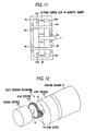
- Fig.12 is a perspective view showing the multirotation type encoder of the related art.
- numeral 10 designates a rotating machine
- numeral 20 designates a first encoder
- numeral 40 designates a second encoder.
- a rotating shaft 12 of the first encoder 20 is attached with a driving gear 34a and the gear 34a is coupled to a driven gear 34b.
- the gear 34b is coupled to the second encoder 40 via a rotating shaft 13.
- the second encoder 40 is transmitted with a rotational number reduced in accordance with a reduction ratio determined by a ratio of teeth numbers of the gear 34a and the gear 34b. That is, a rotational angle of the rotating machine 10 is detected by using the first encoder 20 and a multirotation amount thereof is detected by using the second encoder 40.
- the related art is provided with a mechanical multirotation transmitting mechanism, in order to increase the reduction ratio, the diameter of the driven gear needs to be significantly increased relative to the diameter of the driving gear and there poses a problem of bringing about large-sized formation of the apparatus, and even when a set of gears having small reduction ratios is constituted inmultistage, there poses a problem that the mechanism is complicated and large-sized formation of the apparatus is brought about. Further, in bringing the gears in mesh with each other, there poses a problem that an error is produced at a rotation detector by backlash or wear of meshed faces or a problem that reliability is deteriorated.
- an object of the present invention is to provide a multirotation type encoder which is small-sized even in the case in which the multirotation transmitting portion is at a high reduction ratio, having no mechanical contact portion other than a bearing, having high reliability and long life and dispensing with interchange of a battery.
- the present invention is constructed by the following constitution.
- the respective magnetic gears are magnetically shielded and therefore, a multirotation type encoder strong at an external magnetic field can be provided.
- Fig.1 shows a first embodiment of the invention.
- Fig. 1 is a perspective view of a multirotation type encoder showing the first embodiment of the invention.
- numeral 20 designates a first encoder for detecting an absolute value angle
- numeral 30 designates a speed reducing mechanism comprising a first magnetic gear 31 anda secondmagnetic gear 32
- numeral 40 designates a second encoder
- numeral 41 designates first magnetic field detecting means.
- Fig.2 illustrates schematic views of the magnetic gears of the speed reducing mechanism 30.
- Fig. 2 (a) shows the first magnetic gear 31 of Fig. 1
- Fig. 2 (b) shows the second magnetic gear 32 thereof.
- An arrow mark in the drawings indicates a magnetizing direction.
- the second magnetic gear 32 is magnetized in a circumferential direction at a number of portions thereof.
- the first magnetic gear 31 having a diameter of 5mm is magnetized in 2 poles in a direction orthogonal to a rotating shaft.
- the diameter of the second magnetic gear 32 is set to 5mm, the number of poles thereof is set to 16 poles and the clearance between the magnetic gears is set to 0.3mm.
- the second magnetic gear 32 is arranged at the surrounding of the first magnetic gear 31 via an air gap therebetween in a radial direction. Therefore, when portions of the first magnetic gear 31 and the second magnetic gear 32 having different polarities are facing to each other, an attracting force is operated therebetween and by constituting a transmitting force thereby, rotation of the first magnetic gear 31 is transmitted to the second magnetic gear 32.
- the second encoder 40 comprises the second magnetic gear 32 and the first magnetic field detecting means 41 and detects the amount of multirotation amount of a rotating shaft 11 by detecting the rotational angle of the second magnetic gear 32.
- a number of pieces of the second magnetic gears 32 is set to 3 pieces, the multirotation amount can be detected when the number of pieces is equal to or larger than 1 piece.
- the first magnetic gear 31 and the second magnetic gear 32a are rotatably supported by bearings, not illustrated, the first magnetic gear 31 is rotated from outside and it is measured whether the second magnetic gear 32 is reduced in speed.
- the first magnetic gear is rotated at 6000 rpm and behaviors of rotations of the first magnetic gear 31 and the second magnetic gear 32 are compared.
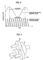
- Fig.3 shows a result of measurement.
- Fig.3 illustrates waveforms for comparing rotational numbers of the first magnetic gear 31 and the second magnetic gear 32 during a constant period of time. It is confirmed that whereas the first magnetic gear 31 is rotated by 8 rotations, the second magnetic gear 32 is rotated by 1 rotation under a condition of a reduction ratio of 1:8. That is, it is known that although a magnetic pole pitch of the first magnetic gear 31 is 7.85mm and a magnetic pole pitch of the second magnetic gear 32 is 0.98mm and both thereof differ from each other by a multiplication factor of about 8, speed is accurately reduced and transmitted.
- Fig. 4 shows a second embodiment of the invention.
- Fig.4 is a perspective view of a magnetic coupling portion comprising magnetic gears showing a second embodiment of the invention.
- a second magnetic gear 32 is arranged relative to a first magnetic gear 31 to overlap each other in an axial direction via an air gap.
- the first magnetic gear 31 is magnetized in a longitudinal direction of a rotating shaft and a number of poles thereof is 2 poles.
- the second magnetic gear 32 is magnetized in a longitudinal direction of a rotating shaft and multiple poles are magnetized in a circumferential direction. Therefore, when portions of the first magnetic gear 31 and the second magnetic gear 32 having different polarities are opposed to each other, an attracting force is operated therebetween, a transmitting force is constituted thereby, and rotation of the first magnetic gear 31 is transmitted to the second magnetic gear 32.
- small-sized formation can be constituted with regard to a diameter direction since the first and the second magnetic gears overlap each other.
- Fig. 5 shows a third embodiment of the invention.
- Fig. 5 is aperspective view of amultirotation type encoder showing the third embodiment of the invention.
- notations 33, 33a, 33b, 33c designate third magnetic gears
- notations 42, 42a, 42b, 42c designate second magnetic field detecting means
- notations 50, 50a, 50b, 50c designate second rotating shafts for connecting the second magnetic gear 32 and the third magnetic gear 33. All of the magnetic gears are rotatably supported by bearings, not illustrated, via the second rotating shaft 50.
- the third magnetic gear 33 is magnetized orthogonally to the rotating shaft 50 and in one direction. Further, 2 pieces or more of the second magnetic field detecting means 42 are arranged at a surrounding of the third magnetic gear 33.
- the embodiment achieves an effect of dispensing with a battery or the like for backup which has been needed in an optical type encoder or the like for holding an absolute value and reducing a number of parts and content of maintenance.
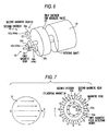
- Fig. 6 shows a fourth embodiment of the invention and Fig.7 shows details of the second magnetic gear 32.
- numeral 35 designates a magnetic yoke
- numeral 36 designates a cylindrical magnet
- numeral 43 designates third magnetic field detecting means.
- the embodiment is substantially the same as the third embodiment, a point of the embodiment which differs therefrom resides in that the second encoder 40 is constituted by the magnetic yoke 35 provided at an inner periphery of the second magnetic gear 32, the cylindrical magnet 36 arranged at an inner portion thereof and the third magnetic field detecting means 43 arranged at an inner portion thereof.
- the speed reducingmechanism portion is constituted by the first magnetic gear 31 magnetized in 2 poles and the second magnetic gear 32 similar to the third embodiment.
- a rotational angle detecting mechanism portion of the second magnetic gear is constituted by the magnetic yoke 35, the cylindrical magnet 36 provided on an inner side thereof and magnetized in 2 poles in a direction orthogonal to a rotating shaft and the second magnetic field detecting means 42 arranged at a space portion on an inner side thereof.
- the magnetic yoke 35 isolates a magnetic circuit of the magnetic speed reducing mechanism constituted by multiple pole magnetizing magnets of the second magnetic gear 32 and the magnetic circuit of the cylindrical magnet 36 thereby prevent magnetic interference from being brought about between the two magnetic circuits.
- a thin type speed reducing mechanism simultaneously having a speed reducing function and a rotational angle detecting function can be constituted, small-sized formation in an axial direction can be constituted and an ultra small-sized multirotation type encoder can be realized. Further, since the magnetic interference is not present, smooth speed reduction of the magnetic gear can be carried out and accuracy of detecting the rotational angle can further be promoted.
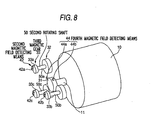
- Fig. 8 shows a fifth embodiment of the invention.
- notations 44, 44a, 44b designate fourth magnetic field detecting means.
- the embodiment is substantially the same as the first embodiment, a point of the embodiment which differs therefrom resides in that the first encoder 20 is constituted by arranging the first magnetic gear 31 and the fourth magnetic field detecting means 44a, 44b at the surrounding of the first magnetic gear 31 via an air gap therebetween. Since a sine wave and a cosine wave can be detected from the fourth magnetic field detecting means 44, the rotational angle of the first magnetic gear can be known by calculating inverse tangent similar to the third embodiment.
- operation and effect of the embodiment is similar to those of the first embodiment, further small-sized formation can be constituted with regard to the axial direction.
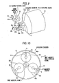
- Fig. 9 shows a sixth embodiment of the invention.
- the embodiment is substantially the same as the fifth embodiment.
- a point of the embodiment which differs therefrom resides in that the first magnetic gear 31 is formed in a cylindrical shape, a uniform magnetic field in one direction is generated in a direction orthogonal to a center axis thereof and fourth magnetic field detecting means 44, 44c, 44d are arranged at inside of an air gap of the first magnetic gear 31 by a predetermined phase difference therebetween.
- a sine wave and a cosine wave can be detected from the fourth magnetic field detecting means 44 and therefore, the rotational angle of the first magnetic gear can be known by calculating inverse tangent similar to the third embodiment. Operation and effect thereof are similar to those of the fifth embodiment.
- Fig.10 shows a magnetic gear portion which is a seventh embodiment of the invention.
- numeral 60 designates a magnetic damper and numeral 70 designates a frame.
- the magnetic damper 60 constituted by a magnetic body is arranged at an outer peripheral portion of the second magnetic gear 32 via an air gap therebetween and the magnetic damper is arranged on an extended line connecting a center of the first magnetic gear 31 and a center of the second magnetic gear 32.
- the first magnetic gear 31 and the second magnetic gear 32 are opposed to each other via a small clearance (0.1mm or smaller), the radial load is applied to the bearings holding the respective magnetic gears by the magnetic attractive force between the first magnetic gear 31 and the second magnetic gear 32, since the magnetic damper 60 is provided, it is not necessary to enlarge the bearings by an amount in correspondence with an amount of the radial load and the radial load is alleviated. Therefore, with the present constitution, small side of the encoder can be ensured and long life formation of the bearings can be achieved.
- Fig. 11 shows a magnetic gear portion which is an eighth embodiment of the invention.
- Fig.11 shows a sectional view at a position the same as that of an A-O-B section in Fig.10 of the seventh embodiment.
- numeral 80 designates a frame serving also as damper 80 and numeral 90 designates a bearing.
- the frame serving also as damper 80 is constituted by integrating the frame 70 and the magnetic damper 60 of the seventh embodiment.
- the frame serving also as magnetic damper 80 By providing the frame serving also as magnetic damper 80, the number of usedparts canbe reduced, further, magnetic shielding can be constituted thereby and therefore, influence of external magnetism can also be prevented.
- a first magnetic gear connected directly to a rotating shaft and magnetized in multiple poles and at least one piece of secondmagnetic gear arranged opposedly to the first magnetic gear in noncontact and magnetized with multiple poles by a number lager than that of the first magnetic gear, amultirotation amount is counted by detecting the rotational angle of the second magnetic gear and therefore, an effect of providing a multirotation type encoder is achieved which is small-sized even in the case in which a multirotation transmitting portion is constituted by a high reduction ratio, having no mechanical contact portion other than a bearing, having high reliability and long life and dispensing with interchange of a battery.
- a reliable multirotation type encoder can be provided against external vibration by arranging a magnetic damper and small-sized formation and long life formation thereof can be achieved.
Landscapes
- Physics & Mathematics (AREA)
- General Physics & Mathematics (AREA)
- Transmission And Conversion Of Sensor Element Output (AREA)
- Measurement Of Length, Angles, Or The Like Using Electric Or Magnetic Means (AREA)
Abstract
Description
Furthermore, since the rotational angle is detected by counting teeth numbers of the gears at respective stages and therefore, there poses a problem that an electronic part and a battery are needed for storing a count number and cost and time are needed for interchanging the battery periodically. Further, in order to accurately determine a boundary reaching two rotations from one rotation, an absolute value encoder within one rotation needs to separately provide on the rotating shaft.
Claims (10)
- A multirotation type encoder comprising:wherein the second encoder comprises:a first encoder attached to a rotating shaft of a rotating machine for detecting an absolute rotational angle within one rotation; anda second encoder for counting a multirotaion amount of the rotating shaft by using a speed reducing mechanism by magnetic coupling,a first magnetic gear directly connected to the rotating shaft and magnetized in multiple poles;at least one second magnetic gear arranged opposedly to the first magnetic gear in noncontact and having magnetic poles by a number larger than a number of magnetic poles of the first magnetic gear; andfirst magnetic field detecting means for detecting a rotational angle of the second magnetic gear.
- The multirotation type encoder according to claim 1, wherein the second magnetic gear is arranged to the first magnetic gear via an air gap therebetween in a radial direction thereof.
- The multirotation type encoder according to claim 1, wherein the second magnetic gear is arranged in an axial direction of the first magnetic gear to overlap the first magnetic gear.
- The multirotation type encoder according to any one of claims 1 through 3, wherein the second encoder further comprises:a third magnetic gear, provided at a second rotating shaft supporting the second magnetic gear, and magnetized in multiple poles; andsecondmagnetic fielddetectingmeans arranged with at least two pieces thereof to one piece of the third magnetic gear via an air gap between the third magnetic gear and the second magnetic field detecting means.
- The multirotation type encoder according to any one of claims 1 through 3, wherein the second encoder further comprises:a magnetic yoke in a ring-like shape provided at an inner periphery of the second magnetic gear;a cylindrical magnet provided at an inner periphery of the magnetic yoke andmagnetized in two poles; andthird magnetic field detecting means arranged at an inner portion of the cylindrical magnet by at least two pieces thereof.
- The multirotation type encoder according to any one of claims 1 through 5, wherein the first encoder comprises:the first magnetic gear; andfourth magneticfield detectingmeansarranged by at least two pieces thereof via an air gap between the first magnetic gear and the fourth magnetic field detecting means.
- The multirotation type encoder according to any one of claims 1 through 6, wherein the first magnetic gear is formed in a cylindrical shape andmagnetized to generate a magnetic field in one direction uniformly in a direction orthogonal to a center axis thereof.
- The multirotation type encoder according to any one of claims 1 through 7, wherein a magnetic damper comprising a magnetic body is arranged at an outer peripheral portion of the second magnetic gear via an air gap therebetween.
- The multirotation type encoder according to claim 8, wherein the magnetic damper is arranged on an extended line connecting a center of the first magnetic gear and a center of the second magnetic gear.
- The multirotation type encoder according to Claim 8 or 9, wherein the magnetic damper is arranged at an inner peripheral portion of a frame substantially in a cylindrical shape for supporting the rotating shaft and a shaft of the magnetic gear by a structure integrated therewith.
Applications Claiming Priority (7)
| Application Number | Priority Date | Filing Date | Title |
|---|---|---|---|
| JP2001322393 | 2001-10-19 | ||
| JP2001322393 | 2001-10-19 | ||
| JP2002066293 | 2002-03-12 | ||
| JP2002066293 | 2002-03-12 | ||
| JP2002098152 | 2002-04-01 | ||
| JP2002098152 | 2002-04-01 | ||
| PCT/JP2002/010693 WO2003036237A1 (en) | 2001-10-19 | 2002-10-15 | Multirotation type encoder |
Publications (3)
| Publication Number | Publication Date |
|---|---|
| EP1437575A1 true EP1437575A1 (en) | 2004-07-14 |
| EP1437575A4 EP1437575A4 (en) | 2005-02-23 |
| EP1437575B1 EP1437575B1 (en) | 2006-08-30 |
Family
ID=27347699
Family Applications (1)
| Application Number | Title | Priority Date | Filing Date |
|---|---|---|---|
| EP02802015A Expired - Lifetime EP1437575B1 (en) | 2001-10-19 | 2002-10-15 | Multirotation type encoder |
Country Status (8)
| Country | Link |
|---|---|
| US (1) | US7042211B2 (en) |
| EP (1) | EP1437575B1 (en) |
| JP (1) | JP4258376B2 (en) |
| KR (1) | KR100913631B1 (en) |
| CN (1) | CN1267707C (en) |
| CA (1) | CA2463735A1 (en) |
| DE (1) | DE60214410T2 (en) |
| WO (1) | WO2003036237A1 (en) |
Cited By (7)
| Publication number | Priority date | Publication date | Assignee | Title |
|---|---|---|---|---|
| EP1790949A2 (en) | 2005-11-29 | 2007-05-30 | SICK STEGMANN GmbH | Device for the absolute measurement of the linear or rotational position of an object to be measured |
| FR2897681A1 (en) * | 2006-02-20 | 2007-08-24 | Somfy Sas | Rotation sensor for electro-mechanical actuator, has polar wheels and clock wheel associated to respective magnetic sensing probes, and magnetic marks which when passed in front of probe activates probe |
| FR2919385A1 (en) * | 2007-07-24 | 2009-01-30 | Moving Magnet Tech Mmt | NON-CONTACT MAGNETIC SENSOR WITH ABSOLUTE MULTITOUR POSITION WITH THROUGH SHAFT |
| CN101504292B (en) * | 2009-02-23 | 2010-11-03 | 孙成 | Multi-slewing absolute magnetic encoder capable of reducing standby power consumption |
| EP2180297A3 (en) * | 2008-10-24 | 2014-03-05 | Sumitomo Heavy Industries, LTD. | Rotation detector attachment decelerating device |
| EP3023743A1 (en) * | 2014-11-19 | 2016-05-25 | Steering Solutions IP Holding Corporation | Handwheel position detection system |
| EP3385678A1 (en) * | 2017-04-06 | 2018-10-10 | Melexis Technologies SA | Rotary position sensor |
Families Citing this family (47)
| Publication number | Priority date | Publication date | Assignee | Title |
|---|---|---|---|---|
| JP2005031055A (en) | 2003-06-20 | 2005-02-03 | Yazaki Corp | Rotation angle detector |
| JP2006220530A (en) * | 2005-02-10 | 2006-08-24 | Matsushita Electric Ind Co Ltd | Absolute rotation angle detector |
| JP2007113932A (en) * | 2005-10-18 | 2007-05-10 | Harmonic Drive Syst Ind Co Ltd | Multi-turn absolute encoder for geared motor |
| FR2893410B1 (en) * | 2005-11-15 | 2008-12-05 | Moving Magnet Tech Mmt | MAGNETIC ANGULAR POSITION SENSOR FOR RACE UP TO 360 |
| DE102006006359A1 (en) * | 2006-02-11 | 2007-08-16 | Leopold Kostal Gmbh & Co. Kg | Angle of rotation sensor and method for determining the absolute angular position of a body rotatable over several rounds |
| WO2008123997A1 (en) * | 2007-04-02 | 2008-10-16 | Magnetic Torque International. Ltd. | Gear with multiple magnetic tooth engagement |
| US9161844B2 (en) * | 2007-04-03 | 2015-10-20 | Finsbury (Development) Limited | Method of using a trial acetabular cup for insertion of an acetabular prosthesis |
| US7697305B2 (en) * | 2007-04-27 | 2010-04-13 | Hewlett-Packard Development Company, L.P. | Apparatus and method for enhancing conductivity |
| US8294457B2 (en) | 2007-09-07 | 2012-10-23 | Joral Llc | Rotary magnetic encoder assembly, chip and method |
| CN102066879B (en) * | 2008-06-20 | 2013-01-02 | 谐波传动系统有限公司 | Magnetic encoder and actuator |
| KR200450196Y1 (en) * | 2008-11-03 | 2010-09-10 | 파인-웨이 프리시즌 엔터프라이즈 컴패니 리미티드 | Automatic tool changer |
| JP5331505B2 (en) * | 2009-02-13 | 2013-10-30 | 株式会社ショーワ | Rotation angle detection device and steering device |
| JP2010240186A (en) * | 2009-04-07 | 2010-10-28 | Toshiba Corp | X-ray CT system |
| DE202009006227U1 (en) * | 2009-04-30 | 2010-10-21 | Dr. Fritz Faulhaber Gmbh & Co. Kg | Electric actuator |
| DE102009031176A1 (en) * | 2009-06-29 | 2010-12-30 | Leopold Kostal Gmbh & Co. Kg | angle sensor |
| DE102009048389B4 (en) * | 2009-10-06 | 2019-12-19 | Asm Automation Sensorik Messtechnik Gmbh | Arrangement for detection of more than one revolution using magnets as a position transmitter |
| US20110121823A1 (en) * | 2009-11-24 | 2011-05-26 | Gm Global Encoder Gear And Sensor Assembly | Meshing encoder gear and sensor assembly |
| US20110213571A1 (en) * | 2010-02-26 | 2011-09-01 | General Electric Company | Sectional magnetic encoding method and system for measuring rotating shaft parameters |
| WO2011119597A2 (en) * | 2010-03-23 | 2011-09-29 | Williams Controls. Inc. | Configurable non-contact position sensor |
| FR2964190B1 (en) * | 2010-08-24 | 2013-02-08 | Moving Magnet Tech | MAGNETIC DETECTION DEVICE WITH ABSOLUTE MULTITOUR POSITION |
| MY165856A (en) * | 2010-08-24 | 2018-05-18 | Rotork Controls | Apparatus adapted to provide an indication of an angular position of an input member over multiple turns |
| JP5671353B2 (en) * | 2011-01-14 | 2015-02-18 | 株式会社アイエイアイ | Encoder, motor unit, and actuator system |
| JP5759867B2 (en) | 2011-10-28 | 2015-08-05 | 山洋電気株式会社 | Magnetic encoder |
| JP5420624B2 (en) * | 2011-11-14 | 2014-02-19 | オリエンタルモーター株式会社 | Multi-rotation absolute rotation angle detection device and method for detecting absolute rotation angle |
| JP6109151B2 (en) * | 2012-03-30 | 2017-04-05 | 株式会社デンソーウェーブ | Encoder, encoder mounting method, torque limiting mechanism, drive device, and robot device |
| US8456271B1 (en) * | 2012-04-04 | 2013-06-04 | Ifm Electronic Gmbh | Optical proximity switch |
| JP2014115234A (en) * | 2012-12-12 | 2014-06-26 | Iai Corp | Mechanical absolute unit, mechanical absolute encoder, and actuator |
| DE102012024383A1 (en) * | 2012-12-13 | 2014-06-18 | Valeo Schalter Und Sensoren Gmbh | Device having a torque sensor device and a steering angle sensor device for a motor vehicle, motor vehicle and method for producing a device |
| CN103019298B (en) * | 2012-12-21 | 2014-10-22 | 福州工大台钻有限公司 | Simulative handle for numerical control bench drill |
| CN103925933B (en) * | 2013-01-11 | 2016-12-28 | 江苏多维科技有限公司 | A kind of multi-turn absolute magnetic encoder |
| JP6224349B2 (en) * | 2013-05-15 | 2017-11-01 | 株式会社アイエイアイ | Stepping motor control system and stepping motor control method |
| JP6372385B2 (en) * | 2015-02-10 | 2018-08-15 | 新日鐵住金株式会社 | Eddy current heating device |
| JP6375980B2 (en) * | 2015-02-10 | 2018-08-22 | 新日鐵住金株式会社 | Eddy current heating device |
| JP6353380B2 (en) * | 2015-02-24 | 2018-07-04 | メレキシス テクノロジーズ エス エー | Rotation detector |
| CN106225814B (en) * | 2016-07-14 | 2018-11-20 | 长春禹衡光学有限公司 | A kind of gear type magnetic encoder |
| DE102016115310A1 (en) * | 2016-08-18 | 2018-02-22 | Valeo Schalter Und Sensoren Gmbh | Sensor system for determining an absolute angle of rotation of a shaft, method for determining an absolute angle of rotation of a shaft and vehicle with a sensor system |
| JP6877170B2 (en) * | 2017-02-14 | 2021-05-26 | 日本電産サンキョー株式会社 | Rotary encoder and its absolute angle position detection method |
| JP7234577B2 (en) * | 2018-10-31 | 2023-03-08 | セイコーエプソン株式会社 | ROBOT SYSTEM, ROBOT CONTROL METHOD, AND ENCODER |
| JP7193635B2 (en) * | 2018-12-06 | 2022-12-20 | 株式会社ハーモニック・ドライブ・システムズ | Dual absolute encoder |
| JP7293660B2 (en) * | 2019-01-18 | 2023-06-20 | 株式会社ジェイテクト | Rotation angle detector |
| US11946773B2 (en) * | 2019-03-28 | 2024-04-02 | Denso Corporation | Motor rotation and position detection device and control unit |
| JP7404841B2 (en) * | 2019-12-13 | 2023-12-26 | 株式会社デンソー | rotating electric machine |
| CN111609871A (en) * | 2020-06-08 | 2020-09-01 | 哈尔滨理工大学 | A longitudinal multi-gear multi-turn magnetic encoder |
| JP7480687B2 (en) * | 2020-11-26 | 2024-05-10 | セイコーエプソン株式会社 | Encoder unit, drive device and robot |
| AT524982A1 (en) | 2021-04-09 | 2022-11-15 | Schiebel Antriebstechnik Gmbh | MT sensor |
| JP7671660B2 (en) * | 2021-09-14 | 2025-05-02 | Ckd株式会社 | Rotary Encoder |
| TWI838998B (en) * | 2022-12-02 | 2024-04-11 | 東佑達自動化科技股份有限公司 | Drive sensing device with magnetic non-contact transmission unit |
Family Cites Families (12)
| Publication number | Priority date | Publication date | Assignee | Title |
|---|---|---|---|---|
| JPS5764113A (en) | 1980-10-08 | 1982-04-19 | Toko Seiki Kk | Liquid enclosed type counter |
| DE3228412C2 (en) * | 1981-07-30 | 1985-04-04 | Leo G. Ewa Beach Hawaii Nickoladze | transmission |
| JPS5866055A (en) | 1981-10-15 | 1983-04-20 | Toyota Motor Corp | Rotation sensor |
| JPS596774U (en) | 1982-07-05 | 1984-01-17 | 第一精工株式会社 | Rotation sensor |
| JPH07113556B2 (en) | 1986-10-31 | 1995-12-06 | トヨタ自動車株式会社 | Absolute Encoder |
| JPH02212769A (en) | 1989-02-13 | 1990-08-23 | Yokogawa Electric Corp | Revolution sensor |
| JP3206204B2 (en) | 1992-05-22 | 2001-09-10 | 株式会社デンソー | Throttle position sensor |
| WO1997006404A2 (en) * | 1995-08-02 | 1997-02-20 | Durakool Inc | Gear tooth sensor with improved resolution and stability |
| JP3906474B2 (en) | 1997-08-22 | 2007-04-18 | 株式会社安川電機 | Multi-rotation absolute encoder |
| US6426577B1 (en) * | 1998-05-01 | 2002-07-30 | Nisso Electric Corporation | Thrust-controllable rotary synchronous machine |
| US20010009367A1 (en) * | 1999-02-26 | 2001-07-26 | Dieter Seitzer | Sensor device to record speed and motion direction of an object, especially rotational speed and direction of a rotating object |
| US20020130657A1 (en) * | 2001-01-29 | 2002-09-19 | Hui Li | Absolute angular position sensor by using gear |
-
2002
- 2002-10-15 CN CNB028207726A patent/CN1267707C/en not_active Expired - Fee Related
- 2002-10-15 US US10/492,846 patent/US7042211B2/en not_active Expired - Fee Related
- 2002-10-15 CA CA002463735A patent/CA2463735A1/en not_active Abandoned
- 2002-10-15 EP EP02802015A patent/EP1437575B1/en not_active Expired - Lifetime
- 2002-10-15 KR KR1020047005763A patent/KR100913631B1/en not_active Expired - Fee Related
- 2002-10-15 WO PCT/JP2002/010693 patent/WO2003036237A1/en not_active Ceased
- 2002-10-15 JP JP2003538690A patent/JP4258376B2/en not_active Expired - Fee Related
- 2002-10-15 DE DE60214410T patent/DE60214410T2/en not_active Expired - Lifetime
Cited By (13)
| Publication number | Priority date | Publication date | Assignee | Title |
|---|---|---|---|---|
| EP1790949A2 (en) | 2005-11-29 | 2007-05-30 | SICK STEGMANN GmbH | Device for the absolute measurement of the linear or rotational position of an object to be measured |
| FR2897681A1 (en) * | 2006-02-20 | 2007-08-24 | Somfy Sas | Rotation sensor for electro-mechanical actuator, has polar wheels and clock wheel associated to respective magnetic sensing probes, and magnetic marks which when passed in front of probe activates probe |
| WO2007096738A1 (en) * | 2006-02-20 | 2007-08-30 | Somfy Sas | Absolute position sensor and method of operation of such a sensor |
| KR101497740B1 (en) * | 2007-07-24 | 2015-03-02 | 무빙 마그네트 테크놀로지스 | Non-contact multi-turn absolute position magnetic sensor comprising a through-shaft |
| FR2919385A1 (en) * | 2007-07-24 | 2009-01-30 | Moving Magnet Tech Mmt | NON-CONTACT MAGNETIC SENSOR WITH ABSOLUTE MULTITOUR POSITION WITH THROUGH SHAFT |
| WO2009047401A3 (en) * | 2007-07-24 | 2009-08-20 | Moving Magnet Tech Mmt | Non-contact multi-turn absolute position magnetic sensor comprising a through-shaft |
| US9097559B2 (en) | 2007-07-24 | 2015-08-04 | Moving Magnet Technologies | Non-contact multi-turn absolute position magnetic sensor comprising a through-shaft |
| EP2180297A3 (en) * | 2008-10-24 | 2014-03-05 | Sumitomo Heavy Industries, LTD. | Rotation detector attachment decelerating device |
| CN101504292B (en) * | 2009-02-23 | 2010-11-03 | 孙成 | Multi-slewing absolute magnetic encoder capable of reducing standby power consumption |
| EP3023743A1 (en) * | 2014-11-19 | 2016-05-25 | Steering Solutions IP Holding Corporation | Handwheel position detection system |
| EP3385678A1 (en) * | 2017-04-06 | 2018-10-10 | Melexis Technologies SA | Rotary position sensor |
| US10571302B2 (en) | 2017-04-06 | 2020-02-25 | Melexis Technologies Sa | Rotary position sensor |
| US10571303B2 (en) | 2017-04-06 | 2020-02-25 | Melexis Technologies Sa | Redundant fault detection device and method |
Also Published As
| Publication number | Publication date |
|---|---|
| KR20040058208A (en) | 2004-07-03 |
| US20040246148A1 (en) | 2004-12-09 |
| CN1267707C (en) | 2006-08-02 |
| CA2463735A1 (en) | 2003-05-01 |
| EP1437575A4 (en) | 2005-02-23 |
| EP1437575B1 (en) | 2006-08-30 |
| DE60214410T2 (en) | 2006-12-21 |
| CN1571916A (en) | 2005-01-26 |
| JPWO2003036237A1 (en) | 2005-02-17 |
| DE60214410D1 (en) | 2006-10-12 |
| WO2003036237A1 (en) | 2003-05-01 |
| KR100913631B1 (en) | 2009-08-24 |
| US7042211B2 (en) | 2006-05-09 |
| JP4258376B2 (en) | 2009-04-30 |
Similar Documents
| Publication | Publication Date | Title |
|---|---|---|
| US7042211B2 (en) | Multirotation type encoder | |
| US7791334B2 (en) | Rotary encoder and method for operation of a rotary encoder | |
| US7501812B2 (en) | Combined sensor and bearing assembly and method of magnetizing element of rotation sensor | |
| US7639004B2 (en) | Apparatus for sensing angular displacement between first and second rotating shafts including flux collectors | |
| US7261012B2 (en) | Gear drive unit with speed measurement | |
| US7021160B2 (en) | Apparatus for sensing position and/or torque | |
| CN104011984B (en) | Motor, motor system and motor encoder | |
| US7292028B2 (en) | Apparatus for sensing the absolute-value angle of a shaft | |
| JP4741798B2 (en) | Gear mechanism and rotary encoder provided with the gear mechanism | |
| US7019516B2 (en) | Magnetic sensor unit less responsive to leaking magnetic flux | |
| JP2000353051A (en) | Method for pointing information and pointing device | |
| KR20080077369A (en) | Magnetic Angular Position Sensor with 360 Degree Range | |
| US11913784B2 (en) | Reduction mechanism and absolute encoder | |
| CN1033092A (en) | The bearing that magnetic field detector is arranged | |
| US20220155051A1 (en) | Absolute encoder | |
| US20250189294A1 (en) | Absolute encoder | |
| EP2180297B1 (en) | Rotation detector attachment decelerating device | |
| EP0721106A2 (en) | Improved switched reluctance speed sensor | |
| EP1477773B1 (en) | Magnetic turning angle detector | |
| JP7848955B2 (en) | Absolute encoder | |
| TWI917599B (en) | Absolute Encoder | |
| WO2022209746A1 (en) | Absolute encoder | |
| JP4161248B2 (en) | Combined detector | |
| TWI917600B (en) | Absolute Encoder | |
| GB2321969A (en) | Rotary coupling alignment |
Legal Events
| Date | Code | Title | Description |
|---|---|---|---|
| PUAI | Public reference made under article 153(3) epc to a published international application that has entered the european phase |
Free format text: ORIGINAL CODE: 0009012 |
|
| 17P | Request for examination filed |
Effective date: 20040416 |
|
| AK | Designated contracting states |
Kind code of ref document: A1 Designated state(s): AT BE BG CH CY CZ DE DK EE ES FI FR GB GR IE IT LI LU MC NL PT SE SK TR |
|
| A4 | Supplementary search report drawn up and despatched |
Effective date: 20050112 |
|
| 17Q | First examination report despatched |
Effective date: 20050609 |
|
| GRAP | Despatch of communication of intention to grant a patent |
Free format text: ORIGINAL CODE: EPIDOSNIGR1 |
|
| GRAS | Grant fee paid |
Free format text: ORIGINAL CODE: EPIDOSNIGR3 |
|
| GRAA | (expected) grant |
Free format text: ORIGINAL CODE: 0009210 |
|
| AK | Designated contracting states |
Kind code of ref document: B1 Designated state(s): DE FR GB |
|
| REG | Reference to a national code |
Ref country code: GB Ref legal event code: FG4D |
|
| REF | Corresponds to: |
Ref document number: 60214410 Country of ref document: DE Date of ref document: 20061012 Kind code of ref document: P |
|
| ET | Fr: translation filed | ||
| PLBE | No opposition filed within time limit |
Free format text: ORIGINAL CODE: 0009261 |
|
| STAA | Information on the status of an ep patent application or granted ep patent |
Free format text: STATUS: NO OPPOSITION FILED WITHIN TIME LIMIT |
|
| 26N | No opposition filed |
Effective date: 20070531 |
|
| PGFP | Annual fee paid to national office [announced via postgrant information from national office to epo] |
Ref country code: FR Payment date: 20081014 Year of fee payment: 7 |
|
| PGFP | Annual fee paid to national office [announced via postgrant information from national office to epo] |
Ref country code: GB Payment date: 20081015 Year of fee payment: 7 |
|
| REG | Reference to a national code |
Ref country code: FR Ref legal event code: ST Effective date: 20100630 |
|
| PG25 | Lapsed in a contracting state [announced via postgrant information from national office to epo] |
Ref country code: FR Free format text: LAPSE BECAUSE OF NON-PAYMENT OF DUE FEES Effective date: 20091102 |
|
| PG25 | Lapsed in a contracting state [announced via postgrant information from national office to epo] |
Ref country code: GB Free format text: LAPSE BECAUSE OF NON-PAYMENT OF DUE FEES Effective date: 20091015 |
|
| PGFP | Annual fee paid to national office [announced via postgrant information from national office to epo] |
Ref country code: DE Payment date: 20101013 Year of fee payment: 9 |
|
| PG25 | Lapsed in a contracting state [announced via postgrant information from national office to epo] |
Ref country code: DE Free format text: LAPSE BECAUSE OF NON-PAYMENT OF DUE FEES Effective date: 20120501 |
|
| REG | Reference to a national code |
Ref country code: DE Ref legal event code: R119 Ref document number: 60214410 Country of ref document: DE Effective date: 20120501 |