EP1437487A1 - Heating device for filtering element especially for a particle filter and particle filter - Google Patents
Heating device for filtering element especially for a particle filter and particle filter Download PDFInfo
- Publication number
- EP1437487A1 EP1437487A1 EP03029870A EP03029870A EP1437487A1 EP 1437487 A1 EP1437487 A1 EP 1437487A1 EP 03029870 A EP03029870 A EP 03029870A EP 03029870 A EP03029870 A EP 03029870A EP 1437487 A1 EP1437487 A1 EP 1437487A1
- Authority
- EP
- European Patent Office
- Prior art keywords
- housing
- sleeve
- heating device
- heating
- connection
- Prior art date
- Legal status (The legal status is an assumption and is not a legal conclusion. Google has not performed a legal analysis and makes no representation as to the accuracy of the status listed.)
- Granted
Links
Images


Classifications
-
- B—PERFORMING OPERATIONS; TRANSPORTING
- B01—PHYSICAL OR CHEMICAL PROCESSES OR APPARATUS IN GENERAL
- B01D—SEPARATION
- B01D46/00—Filters or filtering processes specially modified for separating dispersed particles from gases or vapours
- B01D46/24—Particle separators, e.g. dust precipitators, using rigid hollow filter bodies
- B01D46/2403—Particle separators, e.g. dust precipitators, using rigid hollow filter bodies characterised by the physical shape or structure of the filtering element
- B01D46/2407—Filter candles
-
- B—PERFORMING OPERATIONS; TRANSPORTING
- B01—PHYSICAL OR CHEMICAL PROCESSES OR APPARATUS IN GENERAL
- B01D—SEPARATION
- B01D46/00—Filters or filtering processes specially modified for separating dispersed particles from gases or vapours
- B01D46/66—Regeneration of the filtering material or filter elements inside the filter
- B01D46/80—Chemical processes for the removal of the retained particles, e.g. by burning
- B01D46/84—Chemical processes for the removal of the retained particles, e.g. by burning by heating only
-
- F—MECHANICAL ENGINEERING; LIGHTING; HEATING; WEAPONS; BLASTING
- F01—MACHINES OR ENGINES IN GENERAL; ENGINE PLANTS IN GENERAL; STEAM ENGINES
- F01N—GAS-FLOW SILENCERS OR EXHAUST APPARATUS FOR MACHINES OR ENGINES IN GENERAL; GAS-FLOW SILENCERS OR EXHAUST APPARATUS FOR INTERNAL COMBUSTION ENGINES
- F01N3/00—Exhaust or silencing apparatus having means for purifying, rendering innocuous, or otherwise treating exhaust
- F01N3/02—Exhaust or silencing apparatus having means for purifying, rendering innocuous, or otherwise treating exhaust for cooling, or for removing solid constituents of, exhaust
- F01N3/021—Exhaust or silencing apparatus having means for purifying, rendering innocuous, or otherwise treating exhaust for cooling, or for removing solid constituents of, exhaust by means of filters
- F01N3/023—Exhaust or silencing apparatus having means for purifying, rendering innocuous, or otherwise treating exhaust for cooling, or for removing solid constituents of, exhaust by means of filters using means for regenerating the filters, e.g. by burning trapped particles
- F01N3/027—Exhaust or silencing apparatus having means for purifying, rendering innocuous, or otherwise treating exhaust for cooling, or for removing solid constituents of, exhaust by means of filters using means for regenerating the filters, e.g. by burning trapped particles using electric or magnetic heating means
-
- B—PERFORMING OPERATIONS; TRANSPORTING
- B01—PHYSICAL OR CHEMICAL PROCESSES OR APPARATUS IN GENERAL
- B01D—SEPARATION
- B01D2279/00—Filters adapted for separating dispersed particles from gases or vapours specially modified for specific uses
- B01D2279/30—Filters adapted for separating dispersed particles from gases or vapours specially modified for specific uses for treatment of exhaust gases from IC Engines
-
- F—MECHANICAL ENGINEERING; LIGHTING; HEATING; WEAPONS; BLASTING
- F01—MACHINES OR ENGINES IN GENERAL; ENGINE PLANTS IN GENERAL; STEAM ENGINES
- F01N—GAS-FLOW SILENCERS OR EXHAUST APPARATUS FOR MACHINES OR ENGINES IN GENERAL; GAS-FLOW SILENCERS OR EXHAUST APPARATUS FOR INTERNAL COMBUSTION ENGINES
- F01N2330/00—Structure of catalyst support or particle filter
- F01N2330/06—Ceramic, e.g. monoliths
-
- F—MECHANICAL ENGINEERING; LIGHTING; HEATING; WEAPONS; BLASTING
- F01—MACHINES OR ENGINES IN GENERAL; ENGINE PLANTS IN GENERAL; STEAM ENGINES
- F01N—GAS-FLOW SILENCERS OR EXHAUST APPARATUS FOR MACHINES OR ENGINES IN GENERAL; GAS-FLOW SILENCERS OR EXHAUST APPARATUS FOR INTERNAL COMBUSTION ENGINES
- F01N2390/00—Arrangements for controlling or regulating exhaust apparatus
- F01N2390/02—Arrangements for controlling or regulating exhaust apparatus using electric components only
-
- F—MECHANICAL ENGINEERING; LIGHTING; HEATING; WEAPONS; BLASTING
- F01—MACHINES OR ENGINES IN GENERAL; ENGINE PLANTS IN GENERAL; STEAM ENGINES
- F01N—GAS-FLOW SILENCERS OR EXHAUST APPARATUS FOR MACHINES OR ENGINES IN GENERAL; GAS-FLOW SILENCERS OR EXHAUST APPARATUS FOR INTERNAL COMBUSTION ENGINES
- F01N3/00—Exhaust or silencing apparatus having means for purifying, rendering innocuous, or otherwise treating exhaust
- F01N3/01—Exhaust or silencing apparatus having means for purifying, rendering innocuous, or otherwise treating exhaust by means of electric or electrostatic separators
Definitions
- the invention relates to a heating device according to the preamble of claim 1 for a filter, in particular a diesel particulate filter Motor vehicle, as well as such a filter overall.
- Modern diesel engines have diesel soot filters for environmental reasons with which the soot particles classified as harmful from the exhaust gases should be filtered out.
- the problem is that clog the diesel soot filter relatively quickly with the soot, so to speak clog.
- heaters are known with which the soot from the Filters with sufficient temperature can be burned away.
- Such a heating device is known from DE 10127223 A. She has a thin tubular heater that runs between filter surfaces.
- a heating device has a thin tubular heater and a connection device for the electrical connection of the tubular heater.
- the connection device is there designed for several tubular heaters, for example three or four Tans. It has a housing in which the heating conductor the tubular heater are merged. This is done on an electrical Connection, which in the following is the only first electrical connection referred to as.
- the connection device the heating device is designed, at least partially, that is possibly together with other institutions, the To fix tubular heaters mechanically.
- the connection device carries on the one hand for the electrical connection of the tubular heating element at. Furthermore, it is connected to the tubular heaters, and This connection helps to attach the tubular heater.
- tubular heaters are provided, they can be advantageous run parallel to and next to each other. This has the advantage that they cause uniform heating.
- the jackets of the tubular heater can be attached to the housing of the connecting device be guided and attached to it.
- Such an attachment is advantageously designed to be non-detachable so that the attachment is also secure and is permanent.
- the jackets of the tubular heater are particularly advantageous welded to the housing of the connecting device.
- the housing it is possible, especially recommended for welding, the housing to train from metal. This also makes it possible to electrically coat the jacket attached to it in a conductive manner.
- the housing form the second electrical connection for the tubular heater. This can then be the ground connection.
- the first electrical connection can be designed such that it is or has a common connecting rail.
- the heating conductors of the tubular radiators are then attached to the connecting rail.
- Such a connecting rail can go from one of the heating conductors to the other run, so for example perpendicular to the longitudinal direction of the Heating conductor or tubular heater.
- the heating conductors are advantageous without bending or deflection connected to the connecting rail, for example welded.
- the first electrical connection can change into a connection pin, advantageous in a single pin.
- These parts can be made in one piece be formed, for example approximately T-shaped.
- the connector pin in turn can protrude from the housing, especially in the longitudinal direction the heating conductor. So it can be easily reached, which is why it is advantageous can be at least partially exposed.
- a tubular sleeve to the housing or to be welded over the connector pin with a certain distance runs to it.
- the sleeve can be metallic, creating a certain mechanical stability is guaranteed as well as welding is possible.
- the sleeve is advantageously shorter than the connecting pin. This causes the connector pin to protrude slightly from the sleeve or can protrude over them.
- the sleeve has a seal.
- This seal is advantageous over the sleeve over, in particular even over the connection pin, which it encloses.
- the sleeve can be electrically insulating or thermal be insulating. It is advantageously elastic, which is its sealing effect strengthened. The advantage of such a seal is that none Moisture penetrate into the connector housing can what protects against corrosion.
- a supply line can sit on the connection pin.
- This can be a lead wire be with an external insulation like that installed in a motor vehicle becomes.
- the supply line is advantageously welded to the connecting pin for a permanent connection, being on the other end carries a connector. In this way the connector is sufficiently far from the high temperatures of the heating device removed and thus protected.
- the seal should be a sealing connection between the supply line and Sleeve and thus also between the feed line and the housing of the connecting device produce.
- the aforementioned sealing effect can thus be advantageous can be achieved.
- Stand as material for such a seal basically many materials to choose from, one hand elastic are and on the other hand have a certain temperature resistance.
- PTFE or silicone is considered to be particularly advantageous, provided that the silicone is sufficiently temperature-resistant.
- the seal is advantageously fastened in the sleeve, so that it is in the Assembly cannot be lost and does not slip during use.
- it can be clamped in the sleeve, for example.
- Therefor offers, for example, a crimping of the end of the sleeve over which protrudes the seal on the inside.
- an additional seal can be provided his. You can between seal and sleeve or between seal and supply line can be provided and, for example, as an even softer and more elastic seal, ring-shaped or sleeve-shaped on the feed line or sleeve.
- the sleeve has a circumferential, inwardly narrower gradation of the sleeve to be provided towards the housing. This acts as a stop for the seal. So the seal can be inserted into the sleeve up to this stop and therefore has the intended installation position.
- the connecting device can be located between the connecting pin and the sleeve have insulation. This is particularly useful when the housing and thus also the sleeve the ground connection for the tubular heater and the connector pin forms the first electrical Connection for the heating conductor forms. As an insulation offer here ceramic casting compounds, which also withstand the high temperatures the tubular heater withstand.
- the connecting device is advantageous designed so that the seal has a maximum temperature Is exposed to 250 °.
- shrink tubing can be used instead of the aforementioned Seal, but also in addition to it.
- heat shrink tubing should have a certain thermal Have durability.
- the housing of the connecting device can be attached to an outer wall of the filter housing. This can around the tubular heater for the electrical connection from the filter housing to lead, an opening may be provided. This opening can be closed with the connecting device or the housing, especially gastight.
- the housing of the connecting device welded to the filter housing for example be advantageous with a seal weld.
- a connection or welding the housing of the connecting device with the filter housing has the advantage that, for example, a common one Ground connection can be made.
- connection device It is not important for the construction of the connection device only attach the gasket so that it has a maximum temperature does not exceed. A supply line and a weld should also be used of the connecting pin with the supply line a certain temperature do not exceed. Otherwise the materials or connections would be not safe from damage.
- FIG 1 is a first embodiment of a heating device according to the invention 11 shown.
- the heating device 11 consists of thin tubular heaters 12, of which the heating device 11 has three pieces.
- the tubular heater 11 in turn each have a jacket 14 and a heating conductor 15 running therein and insulated from the jacket on.
- Tubular heating elements 12 are known per se in the prior art. In particular attention is drawn to DE 10127223.5.
- the tubular heater 12 of the heater 11 run in the connection 17.
- the connection 17 in turn has a housing 19, advantageously made of metal. This is roughly rectangular in itself. It is one piece into a sleeve 20 pointing to the right.
- the tubular heater 12 are in this case by means of sealing plugs 21 in the connection 17 or the housing 19 held.
- the sealing plug 21 can be metallic be and, for example by means of a corresponding welded connection, an electrical connection between the jackets 14 and the housing 19 of the connection 17.
- Coats 14 and plugs 21 can be connected using a laser circumferential weld for a secure connection be connected.
- Sealing plug 21 and housing 19 in turn can be connected by means of a TIG welding. That's an electrical one Connection to the tubular heater 12 possible, for example as Ground connection.
- connection 17 contains a connecting rail 23, which is arranged transversely to the course of the tubular heater 12 and itself extends across their range.
- the connecting rail 23 points in Connection lugs 24 pointing towards the tubular heating element 12, which are welded on, for example.
- the heating conductors 15 of the tubular heating element 12 are fastened, in particular welded on or stapled.
- the connecting bar 23 goes into a connecting pin 26 about.
- This can be in one piece or with a welded joint.
- the connector pin 26 extends from the housing 19 along the central axis of the sleeve 20. There is a piece above the end of the Sleeve 20 over, with a pad 27. This is here as Flattened, but could have a different shape.
- the housing 19 is filled with a potting compound 29, which is insulating is, for example as a ceramic casting compound. So they will Connections of the heating conductor 15 to the connection lugs 24, the connection the tubular heater 12 on the housing 19 and the safe and insulated position of the connector pin 26 within the housing 19 and secured within the sleeve 20.
- the connection of the tubular heater 12 or the jacket 14 to the housing 19 is by the potting compound 29 reinforced. Above all, however, it is the responsibility of the plug 21 in this version.
- FIG. 2 shows an exemplary structure of a round cylindrical diesel soot filter shown. Between two disk-shaped filter flanges 31 the heating device 11 is arranged. To the housing 19 of the Connection 17 shows the side wall 32 an angle 33 inside, which is roughly rectangular. On this is the housing 19th welded by means of the weld seams 35. This is how it is attached and for example a ground connection to the tubular heating element 12.
- a bracket 34 runs parallel to the side wall 32, with which the tubular heater 12 on the side wall 32 or on the diesel particulate filter be held.
- Such a holder is from DE 10300717 A. to see their content in this regard by express reference is made the content of this description.
- the side wall 32 is sealingly connected to the filter flanges 31. Welding the housing 19 to the side wall 32 or the section with the bend 33 has the advantage, as also from FIG 2 it can be seen that sealing is possible here.
- the housing 19 or respectively that Housing of the heating device with the side wall 32 and thus the Filter itself is firmly connected.
- an approximate attachment can be made, for example would still allow movement in the longitudinal direction.
- a further heating device 112 is similar to that in FIG Figure 1 shown.
- the right area is of particular interest here is shown in section.
- From the housing 119 stands, for example in one piece, a sleeve 120 from.
- the connector pin 126 runs therein.
- the sleeve 120 has a shoulder 140, which has a diameter broadening the sleeve causes.
- At the end of the sleeve 120 it has one Bend 141 inwards, for example by pressing in the edge inside.
- a seal 143 is inserted into the sleeve 120.
- it can be a hollow cylinder made of PTFE.
- the seal 143 is up to inserted into sleeve 120 for connection to shoulder 140. she is held inward by means of the bend 141.
- One function of the seal 143 is to provide a housing 119 without one Potting compound 29 according to Figure 1, the connector pin 126 of to keep the sleeve 120 insulated. Furthermore, the seal on the left A front additional seal 145 ends in the shoulder 140 exhibit. This can for example consist of a softer and yet heat-resistant material. This is useful, for example Silicone. A similar rear additional seal 146 is on the right inner end of the seal 143 is provided. To the connector pin 126 a supply line 137 is connected with external insulation 138, for example by welding. Such leads are known from the prior art and can be used as a solid wire or be designed as a wire strand.
- the additional seals 145 and 146 create an absolutely tight seal, i.e. in essentially gas-tight, connection between supply line 137 or its External insulation 138 and the housing 119.
- the additional seals 145 and 146 in corresponding recesses on the seal 143 introduced. This can prevent moisture or the like penetrates into the housing 119 and the electrical contacting, for example by corrosion, destroyed or short circuits or Leakage currents generated.
- FIG Figure 5 A modification of a housing 219 of a heating device 211 is shown in FIG Figure 5 shown.
- the sleeve 120 has a potting compound 229 on. It is therefore not necessary, as in FIG. 4 as a secondary function, the pin 226 spaced and insulated from the sleeve 220 to keep.
- the pin 226 is in turn connected to the lead 237.
- a shrink tube 250 extends over this connection in each case the sleeve 220 and the outer insulation 238 of the lead 237 Pieces are covered. On the one hand, this has a certain effect Sealing function between supply line 237 and housing 219. Furthermore the shrink tube 250 protects the current-carrying connection between pin 226 and supply line 237 against moisture and corrosion as previously stated.
- temperature-resistant shrink tube 250 can be used.
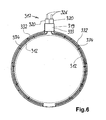
- FIG. 6 shows as with a heating device 311, two tubular heaters 312 or two rows of tubular heaters with a single housing 319 and can be provided with two electrical connections 17.
- the tubular heater can, for example, three tubular heaters accordingly Figures 1 - 5 be formed.
- the structure of the soot filter including side walls 332 and filter flanges 331 corresponds to that described in FIGS. 2 and 3.
- the side wall 332 is not facing inwards Bend, but with an outward-pointing bend 333 provided. This encloses the housing 319 from both sides.
- the holder 334 corresponds to that from FIGS. 2 and 3.
- connection pins protrude from the sleeves 320 326 in the same direction and centered on it.
- the heating conductors of the tubular heating element 312 have their own connector pin 326.
- the ground connections to the tubular heater 312 can in turn via the housing 319 and in particular the side walls 332 of the filter.
Landscapes
- Chemical & Material Sciences (AREA)
- Engineering & Computer Science (AREA)
- Chemical Kinetics & Catalysis (AREA)
- Physics & Mathematics (AREA)
- Geometry (AREA)
- Combustion & Propulsion (AREA)
- Mechanical Engineering (AREA)
- General Engineering & Computer Science (AREA)
- Processes For Solid Components From Exhaust (AREA)
- Resistance Heating (AREA)
- Filtering Of Dispersed Particles In Gases (AREA)
Abstract
Description
Die Erfindung betrifft eine Heizungseinrichtung gemäß dem Oberbegriff des Anspruchs 1 für einen Filter, insbesondere einen Dieselrußfilter eines Kfz, sowie einen solchen Filter insgesamt.The invention relates to a heating device according to the preamble of claim 1 for a filter, in particular a diesel particulate filter Motor vehicle, as well as such a filter overall.
Moderne Dieselmotoren weisen aus Umweltschutzgründen Dieselrußfilter auf, mit denen die als schädlich eingestuften Rußpartikel aus den Abgasen herausgefiltert werden sollen. Dabei besteht das Problem, dass die Dieselrußfilter relativ schnell mit dem Ruß zusetzen und sozusagen verstopfen. Hierzu sind Heizungen bekannt, mit denen der Ruß von dem Filter mit der ausreichenden Temperatur weggebrannt werden kann.Modern diesel engines have diesel soot filters for environmental reasons with which the soot particles classified as harmful from the exhaust gases should be filtered out. The problem is that clog the diesel soot filter relatively quickly with the soot, so to speak clog. For this purpose, heaters are known with which the soot from the Filters with sufficient temperature can be burned away.
Eine derartige Heizeinrichtung ist aus der DE 10127223 A bekannt. Sie weist einen dünnen Rohrheizkörper auf, der zwischen Filterflächen verläuft. Such a heating device is known from DE 10127223 A. she has a thin tubular heater that runs between filter surfaces.
Es ist Aufgabe der Erfindung, eine eingangs genannte Heizungseinrichtung zu schaffen, die für den Einsatz in einem Filter oder einem Dieselrußfilter geeignet ist und insbesondere eine einfache und vorteilhafte mechanische Anbringung sowie elektrische Kontaktierung ermöglicht. Ebenso soll ein solcher Filter mit einer möglichst geeigneten Heizung geschaffen werden.It is an object of the invention to provide a heating device to create that for use in a filter or a diesel particulate filter is suitable and in particular a simple and advantageous mechanical attachment and electrical contacting enabled. Such a filter should also have the most suitable heating be created.
Gelöst wird diese Aufgabe durch eine Heizungseinrichtung mit den Merkmalen des Anspruchs 1 und einen Filter mit den Merkmalen des Anspruchs 16. Vorteilhafte sowie bevorzugte Ausgestaltungen der Erfindung sind Gegenstand der weiteren Ansprüche und werden im folgenden näher erläutert. Der Wortlaut der Ansprüche wird durch ausdrückliche Bezugnahme zum Inhalt der Beschreibung gemacht.This task is solved by a heating device with the Features of claim 1 and a filter with the features of Claim 16. Advantageous and preferred embodiments of the invention are the subject of further claims and are described below explained in more detail. The wording of the claims is by express Reference made to the content of the description.
Erfindungsgemäß weist eine Heizungseinrichtung einen dünnen Rohrheizkörper sowie eine Verbindungseinrichtung für den elektrischen Anschluss des Rohrheizkörpers auf. Die Verbindungseinrichtung ist dabei für mehrere Rohrheizkörper ausgebildet, beispielsweise drei oder vier Rohrheizkörper. Sie weist ein Gehäuse auf, in welchem die Heizleiter der Rohrheizkörper zusammengeführt sind. Dies erfolgt auf einen elektrischen Anschluss, der im folgenden als einziger erster elektrischer Anschluss bezeichnet wird. Des weiteren ist die Verbindungseinrichtung der Heizungseinrichtung dazu ausgebildet, mindestens teilweise, also unter Umständen zusammen mit anderen Einrichtungen, den bzw. die Rohrheizkörper mechanisch zu befestigen. Somit trägt die Verbindungseinrichtung einerseits zum elektrischen Anschluss der Rohrheizkörper bei. Des weiteren ist sie dazu mit den Rohrheizkörpern verbunden, und über diese Verbindung hilft sie, den Rohrheizkörper zu befestigen. According to the invention, a heating device has a thin tubular heater and a connection device for the electrical connection of the tubular heater. The connection device is there designed for several tubular heaters, for example three or four Tans. It has a housing in which the heating conductor the tubular heater are merged. This is done on an electrical Connection, which in the following is the only first electrical connection referred to as. Furthermore, the connection device the heating device is designed, at least partially, that is possibly together with other institutions, the To fix tubular heaters mechanically. Thus, the connection device carries on the one hand for the electrical connection of the tubular heating element at. Furthermore, it is connected to the tubular heaters, and This connection helps to attach the tubular heater.
Wenn mehrere Rohrheizkörper vorgesehen sind, können sie vorteilhaft parallel zueinander und nebeneinander verlaufen. Dies weist den Vorteil auf, dass sie eine gleichmäßige Beheizung bewirken.If several tubular heaters are provided, they can be advantageous run parallel to and next to each other. This has the advantage that they cause uniform heating.
Die Mäntel der Rohrheizkörper können an das Gehäuse der Verbindungseinrichtung geführt und daran befestigt sein. Eine solche Befestigung ist vorteilhaft unlösbar ausgebildet, damit die Befestigung auch sicher und dauerhaft ist. Besonders vorteilhaft sind die Mäntel der Rohrheizkörper an das Gehäuse der Verbindungseinrichtung angeschweißt.The jackets of the tubular heater can be attached to the housing of the connecting device be guided and attached to it. Such an attachment is advantageously designed to be non-detachable so that the attachment is also secure and is permanent. The jackets of the tubular heater are particularly advantageous welded to the housing of the connecting device.
Es ist möglich, insbesondere zum Schweißen empfohlen, das Gehäuse aus Metall auszubilden. Dadurch ist es weiter möglich, den Mantel elektrisch leitend daran zu befestigen. So kann das Gehäuse beispielsweise den zweiten elektrischen Anschluss für die Rohrheizkörper bilden. Dies kann dann der Masseanschluss sein.It is possible, especially recommended for welding, the housing to train from metal. This also makes it possible to electrically coat the jacket attached to it in a conductive manner. For example, the housing form the second electrical connection for the tubular heater. This can then be the ground connection.
Der erste elektrische Anschluss kann dabei derart ausgebildet sein, dass er eine gemeinsame Anschlussschiene ist oder aufweist. An diese Anschlussschiene sind dann die Heizleiter der Rohrheizkörper befestigt. Eine solche Anschlussschiene kann von einem der Heizleiter zu den anderen verlaufen, somit beispielsweise senkrecht zur Längsrichtung der Heizleiter oder Rohrheizkörper. Die Heizleiter sind vorteilhaft ohne Biegung oder Umlenkung mit der Anschlussschiene verbunden, beispielsweise verschweißt.The first electrical connection can be designed such that it is or has a common connecting rail. To this The heating conductors of the tubular radiators are then attached to the connecting rail. Such a connecting rail can go from one of the heating conductors to the other run, so for example perpendicular to the longitudinal direction of the Heating conductor or tubular heater. The heating conductors are advantageous without bending or deflection connected to the connecting rail, for example welded.
Der erste elektrische Anschluss kann in einen Anschlussstift übergehen, vorteilhaft in einen einzigen Anschlussstift. Dazu können diese Teile einteilig ausgebildet sein, beispielsweise etwa T-förmig. Der Anschlussstift wiederum kann aus dem Gehäuse herausragen, insbesondere in Längsrichtung der Heizleiter. So kann er leicht erreicht werden, wozu er vorteilhaft zumindest teilweise frei liegen kann. The first electrical connection can change into a connection pin, advantageous in a single pin. These parts can be made in one piece be formed, for example approximately T-shaped. The connector pin in turn can protrude from the housing, especially in the longitudinal direction the heating conductor. So it can be easily reached, which is why it is advantageous can be at least partially exposed.
Es ist möglich, an dem Gehäuse eine rohrartige Hülse anzubringen bzw. anzuschweißen, die über dem Anschlussstift mit einem gewissen Abstand dazu verläuft. Die Hülse kann metallisch sein, wodurch eine gewisse mechanische Stabilität gewährleistet ist sowie das Verschweißen möglich ist. Vorteilhaft ist die Hülse kürzer als der Anschlussstift. Dies bewirkt, dass der Anschlussstift ein Stück aus der Hülse herausragen bzw. über diese hinüber ragen kann.It is possible to attach a tubular sleeve to the housing or to be welded over the connector pin with a certain distance runs to it. The sleeve can be metallic, creating a certain mechanical stability is guaranteed as well as welding is possible. The sleeve is advantageously shorter than the connecting pin. This causes the connector pin to protrude slightly from the sleeve or can protrude over them.
In weiterer Ausgestaltung der Erfindung kann noch vorgesehen sein, dass die Hülse eine Dichtung aufweist. Diese Dichtung steht vorteilhaft über die Hülse über, insbesondere sogar noch über den Anschlussstift, welchen sie umschließt. Die Hülse kann elektrisch isolierend bzw. thermisch dämmend sein. Vorteilhaft ist sie elastisch, was ihre Dichtungswirkung verstärkt. Der Vorteil einer solchen Dichtung ist der, dass keinerlei Feuchtigkeit in das Gehäuse der Verbindungseinrichtung eindringen kann, was vor Korrosion schützt.In a further embodiment of the invention, it can also be provided that that the sleeve has a seal. This seal is advantageous over the sleeve over, in particular even over the connection pin, which it encloses. The sleeve can be electrically insulating or thermal be insulating. It is advantageously elastic, which is its sealing effect strengthened. The advantage of such a seal is that none Moisture penetrate into the connector housing can what protects against corrosion.
An dem Anschlussstift kann eine Zuleitung sitzen. Diese kann eine Zuleitungslitze sein mit einer Außenisolierung, wie sie in einem Kfz eingebaut wird. Vorteilhaft ist die Zuleitung an den Anschlussstift angeschweißt für eine dauerhafte Verbindung, wobei sie am anderen Ende eine Steckverbindung trägt. Auf diese Weise ist die Steckverbindung ausreichend weit von den hohen Temperaturen der Heizungseinrichtung entfernt und somit geschützt.A supply line can sit on the connection pin. This can be a lead wire be with an external insulation like that installed in a motor vehicle becomes. The supply line is advantageously welded to the connecting pin for a permanent connection, being on the other end carries a connector. In this way the connector is sufficiently far from the high temperatures of the heating device removed and thus protected.
Die Dichtung sollte eine dichtende Verbindung zwischen Zuleitung und Hülse und somit auch zwischen Zuleitung und Gehäuse der Verbindungseinrichtung herstellen. So kann vorteilhaft die vorgenannte Dichtungswirkung erreicht werden. Als Material für eine solche Dichtung stehen grundsätzlich viele Materialien zur Auswahl, die einerseits elastisch sind und andererseits eine gewisse Temperaturbeständigkeit aufweisen. The seal should be a sealing connection between the supply line and Sleeve and thus also between the feed line and the housing of the connecting device produce. The aforementioned sealing effect can thus be advantageous can be achieved. Stand as material for such a seal basically many materials to choose from, one hand elastic are and on the other hand have a certain temperature resistance.
Als besonders vorteilhaft wird hier PTFE oder Silikon angesehen, sofern das Silikon ausreichend temperaturfest ist.PTFE or silicone is considered to be particularly advantageous, provided that the silicone is sufficiently temperature-resistant.
Die Dichtung ist vorteilhaft in der Hülse befestigt, so dass sie bei der Montage nicht verloren gehen kann und im Gebrauch nicht verrutscht. Dazu kann sie beispielsweise in der Hülse eingeklemmt sein. Hierfür bietet sich beispielsweise eine Einbördelung des Endes der Hülse, über welches die Dichtung innenliegend übersteht, nach innen an. Um die Dichtungswirkung noch zu verbessern, kann eine Zusatzdichtung vorgesehen sein. Sie kann zwischen Dichtung und Hülse bzw. zwischen Dichtung und Zuleitung vorgesehen sein und, beispielsweise als noch weichere und elastischere Dichtung, ringförmig oder hülsenförmig an Zuleitung oder Hülse anliegen.The seal is advantageously fastened in the sleeve, so that it is in the Assembly cannot be lost and does not slip during use. For this purpose, it can be clamped in the sleeve, for example. Therefor offers, for example, a crimping of the end of the sleeve over which protrudes the seal on the inside. To the To improve the sealing effect, an additional seal can be provided his. You can between seal and sleeve or between seal and supply line can be provided and, for example, as an even softer and more elastic seal, ring-shaped or sleeve-shaped on the feed line or sleeve.
Des weiteren ist es möglich, zur Montageerleichterung der Dichtung an der Hülse eine umlaufende, nach innen engere Abstufung der Hülse zum Gehäuse hin vorzusehen. Diese wirkt als Anschlag der Dichtung. So kann die Dichtung bis zu diesem Anschlag in die Hülse hineingeführt werden und hat somit die vorgesehene Montagestellung.Furthermore, it is possible to facilitate the assembly of the seal the sleeve has a circumferential, inwardly narrower gradation of the sleeve to be provided towards the housing. This acts as a stop for the seal. So the seal can be inserted into the sleeve up to this stop and therefore has the intended installation position.
Zwischen dem Anschlussstift und der Hülse kann die Verbindungseinrichtung eine Isolierung aufweisen. Dies bietet sich insbesondere dann an, wenn das Gehäuse und somit auch die Hülse den Masseanschluss für die Rohrheizkörper bildet und der Anschlussstift den ersten elektrischen Anschluss für die Heizleiter bildet. Als lsolierung bieten sich hier keramische Vergussmassen an, welche auch den hohen Temperaturen der Rohrheizkörper standhalten. Die Verbindungseinrichtung ist vorteilhaft derart gestaltet, dass die Dichtung einer Temperatur von maximal 250° ausgesetzt ist.The connecting device can be located between the connecting pin and the sleeve have insulation. This is particularly useful when the housing and thus also the sleeve the ground connection for the tubular heater and the connector pin forms the first electrical Connection for the heating conductor forms. As an insulation offer here ceramic casting compounds, which also withstand the high temperatures the tubular heater withstand. The connecting device is advantageous designed so that the seal has a maximum temperature Is exposed to 250 °.
Es ist möglich, über die Hülse einen Schrumpfschlauch zu führen, der sich bis zu einer Zuleitungslitze erstreckt und diese übergreift. Ein solcher Schrumpfschlauch kann beispielsweise anstelle einer vorgenannten Dichtung, aber auch zusätzlich dazu, vorgesehen sein. Der Schrumpfschlauch sollte, wie zuvor angesprochen, eine gewisse thermische Beständigkeit aufweisen.It is possible to run a shrink tube over the sleeve extends to and extends over a lead wire. Such a For example, shrink tubing can be used instead of the aforementioned Seal, but also in addition to it. The As previously mentioned, heat shrink tubing should have a certain thermal Have durability.
Des weiteren ist es möglich, das Gehäuse der Verbindungseinrichtung an einer Außenwandung des Filtergehäuses zu befestigen. Dazu kann, um die Rohrheizkörper für den elektrischen Anschluss aus dem Filtergehäuse zu führen, eine Öffnung vorgesehen sein. Diese Öffnung kann mit der Verbindungseinrichtung bzw. dem Gehäuse verschlossen werden, insbesondere gasdicht. Hierzu kann das Gehäuse der Verbindungseinrichtung beispielsweise an das Filtergehäuse angeschweißt sein, vorteilhaft mit einer Dichtschweißung. Ein Verbinden bzw. Verschweißen des Gehäuses der Verbindungseinrichtung mit dem Filtergehäuse weist den Vorteil auf, dass so auch beispielsweise ein gemeinsamer Masseanschluss hergestellt werden kann.Furthermore, it is possible for the housing of the connecting device to be attached to an outer wall of the filter housing. This can around the tubular heater for the electrical connection from the filter housing to lead, an opening may be provided. This opening can be closed with the connecting device or the housing, especially gastight. For this purpose, the housing of the connecting device welded to the filter housing, for example be advantageous with a seal weld. A connection or welding the housing of the connecting device with the filter housing has the advantage that, for example, a common one Ground connection can be made.
Für den Aufbau der Verbindungseinrichtung ist es von Bedeutung, nicht nur die Dichtung derart anzubringen, dass sie eine maximale Temperatur nicht überschreitet. Ebenso sollte eine Zuleitung sowie eine Verschweißung des Anschlussstiftes mit der Zuleitung eine gewisse Temperatur nicht übersteigen. Ansonsten wären die Materialien oder Verbindungen vor Beschädigungen nicht sicher.It is not important for the construction of the connection device only attach the gasket so that it has a maximum temperature does not exceed. A supply line and a weld should also be used of the connecting pin with the supply line a certain temperature do not exceed. Otherwise the materials or connections would be not safe from damage.
Diese und weitere Merkmale von bevorzugten Weiterbildungen der Erfindung gehen außer aus den Ansprüchen auch aus der Beschreibung und den Zeichnungen hervor, wobei die einzelnen Merkmale jeweils für sich allein oder zu mehreren in Form von Unterkombinationen bei einer Ausführungsform der Erfindung und auf anderen Gebieten verwirklicht sein und vorteilhafte sowie für sich schutzfähige Ausführungen darstellen können, für die hier Schutz beansprucht wird. Die Unterteilung der Anmeldung in einzelne Abschnitte sowie Zwischen-Überschriften beschränken die unter diesen gemachten Aussagen nicht in ihrer Allgemeingültigkeit.These and other features of preferred developments of the invention go not only from the claims but also from the description and the drawings, the individual features for alone or in pairs in the form of sub-combinations in one Embodiment of the invention and implemented in other fields be and represent advantageous and protectable versions for which protection is claimed here. The division of the Limit registration to individual sections and subheadings the statements made under these are not generally applicable.
Ausführungsbeispiele der Erfindung sind in den Zeichnungen schematisch dargestellt und werden im folgenden näher erläutert. In den Zeichnungen zeigen im einzelnen:
- Figur 1
- eine erfindungsgemäße Heizungseinrichtung mit einer Verbindungseinrichtung im Schnitt,
- Figur 2
- eine Innenansicht eines rundzylindrischen Dieselrußfilters mit eingebauter Heizungseinrichtung,
- Figur 3
- eine Seitendarstellung der Anordnung aus Figur 2,
- Figur 4
- einen Teilschnitt durch eine Abwandlung des Gehäuses eines erfindungsgemäßen Filters ähnlich Figur 1 mit einer angeschlossenen Zuleitung,
- Figur 5
- eine Abwandlung des Gehäuses ähnlich Figur 4 und
- Figur 6
- eine Abwandlung einer Heizeinrichtung in einem Filter mit einem Gehäuse einer Verbindungseinrichtung für zwei Rohrheizkörper.
- Figure 1
- a heating device according to the invention with a connecting device in section,
- Figure 2
- an interior view of a round cylindrical diesel soot filter with built-in heating device,
- Figure 3
- 2 shows a side view of the arrangement from FIG. 2,
- Figure 4
- 2 shows a partial section through a modification of the housing of a filter according to the invention similar to FIG. 1 with a connected feed line,
- Figure 5
- a modification of the housing similar to Figure 4 and
- Figure 6
- a modification of a heating device in a filter with a housing of a connecting device for two tubular heaters.
In Figur 1 ist eine erste Ausführung einer erfindungsgemäßen Heizungseinrichtung
11 dargestellt. Sie besteht einerseits aus dünnen Rohrheizkörpern
12, von denen die Heizungseinrichtung 11 drei Stück aufweist.
Die Rohrheizkörper 11 wiederum weisen jeweils einen Mantel 14 und
einen darin verlaufenden, gegenüber dem Mantel isolierten Heizleiter 15
auf. Rohrheizkörper 12 sind an sich im Stand der Technik bekannt. Insbesondere
wird hier auf die DE 10127223.5 hingewiesen. In Figure 1 is a first embodiment of a heating device according to the
Die Rohrheizkörper 12 der Heizeinrichtung 11 laufen in den Anschluss
17. Der Anschluss 17 wiederum weist ein Gehäuse 19 auf, vorteilhaft
aus Metall. Dieses ist an sich in etwa rechteckig. Dabei geht es einstückig
in eine nach rechts weisende Hülse 20 über. Die Rohrheizkörper 12
sind dabei mittels Verschlussstopfen 21 in dem Anschluss 17 bzw. an
dem Gehäuse 19 gehaltert. Die Verschlussstopfen 21 können metallisch
sein und, beispielsweise durch eine entsprechende Schweißverbindung,
eine elektrische Verbindung zwischen den Mänteln 14 und dem Gehäuse
19 des Anschlusses 17 herstellen. Mäntel 14 und Verschlussstopfen
21 können mittels einer Laserumfangs-Schweißung zur sicheren Verbindung
verbunden sein. Verschlussstopfen 21 und Gehäuse 19 wiederum
können mittels einer WIG-Schweißung verbunden sein. So ist ein elektrischer
Anschluss an die Rohrheizkörper 12 möglich, beispielsweise als
Masseanschluss.The
Des weiteren enthält der Anschluss 17 eine Anschlussschiene 23, welche
quer zu dem Verlauf der Rohrheizkörper 12 angeordnet ist und sich
über deren Spannbreite erstreckt. Die Anschlussschiene 23 weist in
Richtung auf die Rohrheizkörper 12 weisende Anschlussfahnen 24 auf,
welche beispielsweise angeschweißt sind. An die Anschlussfahnen 24
wiederum sind die Heizleiter 15 der Rohrheizkörper 12 befestigt, insbesondere
angeschweißt oder kontaktgeheftet.Furthermore, the
In der anderen Richtung geht die Anschlussschiene 23 in einen Anschlussstift
26 über. Dies kann einstückig sein oder mit einer Schweißverbindung.
Der Anschlussstift 26 reicht aus dem Gehäuse 19 entlang
der Mittelachse der Hülse 20. Dabei steht ein Stück über das Ende der
Hülse 20 über, und zwar mit einer Anschlussfläche 27. Diese ist hier als
Abflachung ausgebildet, könnte jedoch auch andere Form aufweisen.In the other direction, the connecting
Das Gehäuse 19 ist mit einer Vergussmasse 29 gefüllt, welche isolierend
ist, beispielsweise als keramische Vergussmasse. So werden die
Anschlüsse der Heizleiter 15 an die Anschlussfahnen 24, die Verbindung
der Rohrheizkörper 12 an dem Gehäuse 19 sowie die sichere und
isolierte Lage des Anschlussstiftes 26 innerhalb des Gehäuses 19 sowie
innerhalb der Hülse 20 gesichert. Die Verbindung der Rohrheizkörper 12
bzw. der Mäntel 14 an das Gehäuse 19 wird durch die Vergussmasse
29 noch verstärkt. Vor allem aber obliegt sie dem Verschlussstopfen 21
bei dieser Ausführung.The
Wie aus Figur 1 zu erkennen ist, können somit auf einfache Art und
Weise drei Rohrheizkörper 12 an einen einzigen Anschluss, nämlich den
Anschlussstift 26, geführt werden. Gleichzeitig ist dabei ein Masseanschluss
für die Rohrheizkörper 12 über das metallische Gehäuse 19 des
Anschlusses 17 möglich.As can be seen from Figure 1, and
Way three
In Figur 2 ist ein beispielhafter Aufbau eines rundzylindrischen Dieselrußfilters
dargestellt. Zwischen zwei scheibenförmigen Filterflanschen 31
ist die Heizungseinrichtung 11 angeordnet. Zu dem Gehäuse 19 des
Anschlusses 17 hin weist die Seitenwand 32 eine Abwinkelung 33 nach
innen auf, welche in etwa rechtwinklig ist. An dieser ist das Gehäuse 19
mittels der Schweißnähte 35 festgeschweißt. So erfolgt eine Befestigung
und beispielsweise ein Masseanschluss an die Rohrheizkörper 12.FIG. 2 shows an exemplary structure of a round cylindrical diesel soot filter
shown. Between two disk-shaped
Parallel zu der Seitenwand 32 verläuft eine Halterung 34, mit welcher
die Rohrheizkörper 12 an der Seitenwand 32 bzw. an dem Dieselrußfilter
gehaltert werden. Eine solche Halterung ist aus der DE 10300717 A
zu entnehmen, deren Inhalt diesbezüglich durch ausdrückliche Bezugnahme
zum Inhalt dieser Beschreibung gemacht wird.A
Die Seitenwand 32 ist dabei dichtend mit den Filterflanschen 31 verbunden.
Das Festschweißen des Gehäuses 19 an der Seitenwand 32 bzw.
dem Abschnitt mit der Abwinkelung 33 hat den Vorteil, wie auch aus Figur
2 zu entnehmen ist, dass hier eine Abdichtung möglich ist. The
Des weiteren ist zu erkennen, dass das Gehäuse 19 bzw. jeweils das
Gehäuse der Heizungseinrichtung mit der Seitenwand 32 und somit dem
Filter an sich fest verbunden ist. Dadurch erfolgt eine gewisse Befestigung
der Heizeinrichtung bzw. der an dem Gehäuse 19 befestigten
Rohrheizkörper 12. So kann beispielsweise durch die Halterung 34 lediglich
eine ungefähre Befestigung vorgenommen werden, welche beispielsweise
noch eine Bewegung in Längsrichtung erlauben würde.
Durch das Festschweißen des Gehäuses 19 an der Seitenwand 32 bzw.
der Abwinkelung 33 erfolgt die endgültige Festlegung.Furthermore, it can be seen that the
In Figur 4 ist eine weitere Heizeinrichtung 112 ähnlich derjenigen aus
Figur 1 dargestellt. Hier interessiert vor allem der rechte Bereich, welcher
im Schnitt dargestellt ist. Von dem Gehäuse 119 steht, beispielsweise
einteilig, eine Hülse 120 ab. Darin verläuft der Anschlussstift 126.
Die Hülse 120 weist einen Absatz 140 auf, welcher eine Durchmesserverbreiterung
der Hülse bewirkt. Am Ende der Hülse 120 weist sie eine
Biegung 141 nach innen auf, beispielsweise durch Eindrücken des Randes
nach innen.A further heating device 112 is similar to that in FIG
Figure 1 shown. The right area is of particular interest here
is shown in section. From the
In die Hülse 120 ist eine Dichtung 143 eingesetzt. Sie kann beispielsweise
ein Hohlzylinder aus PTFE sein. Die Dichtung 143 ist dabei bis
zum Anschluss an den Absatz 140 in die Hülse 120 eingeschoben. Sie
wird mittels der Biegung 141 nach innen darin festgehalten.A
Eine Aufgabe der Dichtung 143 ist es, bei einem Gehäuse 119 ohne eine
Vergussmasse 29 entsprechend Figur 1, den Anschlussstift 126 von
der Hülse 120 isoliert zu halten. Des weiteren kann die Dichtung am linken
Ende in den Absatz 140 hinein eine vordere Zusatzdichtung 145
aufweisen. Diese kann beispielsweise aus einem weicheren und dennoch
hitzebeständigen Material bestehen. Hierfür bietet sich beispielsweise
Silikon an. Eine ähnliche hintere Zusatzdichtung 146 ist am rechten
inneren Ende der Dichtung 143 vorgesehen. An den Anschlussstift
126 ist eine Zuleitung 137 mit einer Außenisolierung 138 angeschlossen,
beispielsweise durch Festschweißen. Derartige Zuleitungen sind
aus dem Stand der Technik bekannt und können als massiver Draht
oder aber als Drahtlitze ausgeführt sein.One function of the
Die Zusatzdichtungen 145 und 146 bewirken eine absolut dichte, also im
wesentlichen gasdichte, Verbindung zwischen Zuleitung 137 bzw. ihrer
Außenisolierung 138 und dem Gehäuse 119. Dabei sind die Zusatzdichtungen
145 und 146 in entsprechende Ausnehmungen an der Dichtung
143 eingebracht. So kann verhindert werden, dass Feuchtigkeit oder
dergleichen in das Gehäuse 119 eindringt und die elektrische Kontaktierung,
beispielsweise durch Korrosion, zerstört oder Kurzschlüsse oder
Kriechströme erzeugt.The
Eine Abwandlung eines Gehäuses 219 einer Heizeinrichtung 211 ist in
Figur 5 dargestellt. Hier weist die Hülse 120 wiederum eine Vergussmasse
229 auf. Somit ist es nicht notwendig, wie bei Figur 4 als Nebenfunktion,
den Anschlussstift 226 von der Hülse 220 beabstandet und isoliert
zu halten.A modification of a
Der Anschlussstift 226 ist wiederum mit der Zuleitung 237 verbunden.
Über diese Verbindung erstreckt sich ein Schrumpfschlauch 250, wobei
jeweils die Hülse 220 und die Außenisolierung 238 der Zuleitung 237 ein
Stück überdeckt werden. Dies bewirkt zum einen wieder eine gewisse
Dichtungsfunktion zwischen Zuleitung 237 und Gehäuse 219. Des weiteren
schützt der Schrumpfschlauch 250 die stromführende Verbindung
zwischen Anschlussstift 226 und Zuleitung 237 vor Feuchtigkeit und Korrosion
wie zuvor angeführt worden ist. Hier kann ein üblicher, möglichst
temperaturbeständiger Schrumpfschlauch 250 verwendet werden. The pin 226 is in turn connected to the
In Figur 6 ist gemäß einer weiteren Möglichkeit der Erfindung dargestellt,
wie bei einer Heizungseinrichtung 311 zwei Rohrheizkörper 312 bzw.
zwei Reihen von Rohrheizkörpern mit einem einzigen Gehäuse 319 und
mit zwei elektrischen Anschlüssen 17 versehen sein können. Die Rohrheizkörper
können beispielsweise je drei Rohrheizkörpern entsprechend
den Figuren 1 - 5 ausgebildet sein.According to a further possibility of the invention, FIG. 6 shows
as with a heating device 311, two
Der Aufbau des Rußfilters samt Seitenwänden 332 und Filterflanschen
331 entspricht dem vorbeschriebenen aus den Figuren 2 und 3. Allerdings
ist hier die Seitenwand 332 nicht mit einer nach innen weisenden
Abwinkelung, sondern mit einer nach außen weisenden Abwinkelung
333 versehen. Diese schließt das Gehäuse 319 von beiden Seiten ein.
Die Halterung 334 entspricht derjenigen aus den Figuren 2 und 3.The structure of the soot filter including
Von dem Gehäuse 319, in welches die beiden Reihen von Rohrheizkörpern
312 von beiden Seiten hineinlaufen, gehen zwei Hülsen 320 radial
nach außen ab. Aus den Hülsen 320 wiederum ragen Anschlussstifte
326 in gleicher Richtung und zentrisch dazu hervor. Dies bedeutet, dass
im vorliegenden Fall die Heizleiter der Rohrheizkörper 312 an jeweils
einen eigenen Anschlussstift 326 geführt sind. Somit können die linke
und die rechte Reihe der Rohrheizkörper 312 unabhängig voneinander
betrieben werden. Dies kann vorteilhaft sein für einen getakteten Betrieb
zum jeweils links- oder rechtsseitigen Abbrennen von Rußablagerungen
in dem Dieselrußfilter. Die Masseanschlüsse an die Rohrheizkörper 312
können wiederum über das Gehäuse 319 und insbesondere die Seitenwände
332 des Filters vorgenommen werden.From the
Claims (16)
dadurch gekennzeichnet, dass der erste elektrische Anschluss eine gemeinsame Anschlussschiene (23) ist, die vorzugsweise senkrecht zur Längsrichtung der Heizleiter (15) verläuft.Heating device according to one of the preceding claims,
characterized in that the first electrical connection is a common connection rail (23) which preferably extends perpendicular to the longitudinal direction of the heating conductors (15).
Applications Claiming Priority (2)
| Application Number | Priority Date | Filing Date | Title |
|---|---|---|---|
| DE10300718A DE10300718A1 (en) | 2003-01-08 | 2003-01-08 | Heating device for a filter, in particular a diesel soot filter |
| DE10300718 | 2003-01-08 |
Publications (2)
| Publication Number | Publication Date |
|---|---|
| EP1437487A1 true EP1437487A1 (en) | 2004-07-14 |
| EP1437487B1 EP1437487B1 (en) | 2005-06-08 |
Family
ID=32478196
Family Applications (1)
| Application Number | Title | Priority Date | Filing Date |
|---|---|---|---|
| EP03029870A Expired - Lifetime EP1437487B1 (en) | 2003-01-08 | 2003-12-27 | Heating device for filtering element especially for a particle filter and particle filter |
Country Status (4)
| Country | Link |
|---|---|
| EP (1) | EP1437487B1 (en) |
| AT (1) | ATE297500T1 (en) |
| DE (2) | DE10300718A1 (en) |
| ES (1) | ES2243852T3 (en) |
Cited By (1)
| Publication number | Priority date | Publication date | Assignee | Title |
|---|---|---|---|---|
| EP3536968A4 (en) * | 2017-02-24 | 2019-12-04 | Mitsubishi Heavy Industries Compressor Corporation | Heater-integrated filter and rotating machine system |
Families Citing this family (1)
| Publication number | Priority date | Publication date | Assignee | Title |
|---|---|---|---|---|
| DE102008017959A1 (en) | 2008-04-08 | 2009-11-05 | Forschungszentrum Karlsruhe Gmbh | Cleanable particle filter |
Citations (4)
| Publication number | Priority date | Publication date | Assignee | Title |
|---|---|---|---|---|
| US4456457A (en) * | 1981-04-28 | 1984-06-26 | Nippon Soken, Inc. | Exhaust gas cleaning device for diesel engine |
| EP0454346A1 (en) * | 1990-04-21 | 1991-10-30 | United Kingdom Atomic Energy Authority | Exhaust particulate filter |
| US5409669A (en) * | 1993-01-25 | 1995-04-25 | Minnesota Mining And Manufacturing Company | Electrically regenerable diesel particulate filter cartridge and filter |
| EP1260262A2 (en) * | 2001-05-22 | 2002-11-27 | E.G.O. Elektro-Gerätebau GmbH | Heating device for filtering element of a particles filter and particles filter |
Family Cites Families (2)
| Publication number | Priority date | Publication date | Assignee | Title |
|---|---|---|---|---|
| DE3712333A1 (en) * | 1987-04-11 | 1988-10-20 | Fev Motorentech Gmbh & Co Kg | REGENERATABLE FILTER ARRANGEMENT FOR REMOVING SOOT PARTICLES FROM EXHAUST GASES |
| DE19530749A1 (en) * | 1995-08-22 | 1997-03-06 | Hjs Fahrzeugtechnik Gmbh & Co | Self-cleaning diesel engine soot filter |
-
2003
- 2003-01-08 DE DE10300718A patent/DE10300718A1/en not_active Withdrawn
- 2003-12-27 DE DE50300629T patent/DE50300629D1/en not_active Expired - Lifetime
- 2003-12-27 ES ES03029870T patent/ES2243852T3/en not_active Expired - Lifetime
- 2003-12-27 AT AT03029870T patent/ATE297500T1/en not_active IP Right Cessation
- 2003-12-27 EP EP03029870A patent/EP1437487B1/en not_active Expired - Lifetime
Patent Citations (4)
| Publication number | Priority date | Publication date | Assignee | Title |
|---|---|---|---|---|
| US4456457A (en) * | 1981-04-28 | 1984-06-26 | Nippon Soken, Inc. | Exhaust gas cleaning device for diesel engine |
| EP0454346A1 (en) * | 1990-04-21 | 1991-10-30 | United Kingdom Atomic Energy Authority | Exhaust particulate filter |
| US5409669A (en) * | 1993-01-25 | 1995-04-25 | Minnesota Mining And Manufacturing Company | Electrically regenerable diesel particulate filter cartridge and filter |
| EP1260262A2 (en) * | 2001-05-22 | 2002-11-27 | E.G.O. Elektro-Gerätebau GmbH | Heating device for filtering element of a particles filter and particles filter |
Cited By (1)
| Publication number | Priority date | Publication date | Assignee | Title |
|---|---|---|---|---|
| EP3536968A4 (en) * | 2017-02-24 | 2019-12-04 | Mitsubishi Heavy Industries Compressor Corporation | Heater-integrated filter and rotating machine system |
Also Published As
| Publication number | Publication date |
|---|---|
| ATE297500T1 (en) | 2005-06-15 |
| DE10300718A1 (en) | 2004-07-22 |
| EP1437487B1 (en) | 2005-06-08 |
| ES2243852T3 (en) | 2005-12-01 |
| DE50300629D1 (en) | 2005-07-14 |
Similar Documents
| Publication | Publication Date | Title |
|---|---|---|
| DE19608675C2 (en) | Temperature measuring device with a media-carrying pipeline | |
| DE112009000215T5 (en) | Ground shield with high thread | |
| EP2407069A1 (en) | Dynamic flow-through heater | |
| EP1375997A1 (en) | Heating device for a pipe and method of production | |
| DE102012005786A1 (en) | Non-rotating electrical connection, in particular for an electrically heatable honeycomb body | |
| EP0848785A1 (en) | Electrical insulation lead-through with a device protecting against the electrocorrosion | |
| DE102013201125B4 (en) | Connector, use of such a connector and method for making an electrical connection in such a connector | |
| DE102012220429A1 (en) | Preheating device for a fuel injection system | |
| DE2835236C2 (en) | Sheathed-element glow plugs for internal combustion engines | |
| DE3443391A1 (en) | GLOW PLUG FOR A DIESEL ENGINE | |
| DE2939725A1 (en) | GALVANIC SENSOR FOR THE OXYGEN CONTENT OF EXHAUST GAS | |
| WO2012175285A1 (en) | Coolable metering module | |
| DE102014005775A1 (en) | battery pole | |
| DE102010035028B4 (en) | Heated cable connectors with insulation and / or protective cover and heatable media cable with at least one cable connector with insulation and / or protective cover | |
| EP1437487B1 (en) | Heating device for filtering element especially for a particle filter and particle filter | |
| DE4303581A1 (en) | Electrically insulating gas-tight passage of at least one electrical conductor through a metallic jacket | |
| DE102019125488B4 (en) | Device for heating blow-by gases | |
| EP2467904A1 (en) | Contact element | |
| EP2016653B1 (en) | Ignition coil for an internal combustion engine, in particular of a motor vehicle | |
| DE10023395B4 (en) | Ceramic heater and mounting structure | |
| DE102016111258A1 (en) | Heating cartridge with a protective tube | |
| DE3500662C2 (en) | ||
| DE69103115T2 (en) | Shielded, waterproof and electrically insulated electrical connector. | |
| EP2101542B1 (en) | Attachment assembly for a tubular electric heating element | |
| DE102021116420A1 (en) | connection arrangement |
Legal Events
| Date | Code | Title | Description |
|---|---|---|---|
| PUAI | Public reference made under article 153(3) epc to a published international application that has entered the european phase |
Free format text: ORIGINAL CODE: 0009012 |
|
| AK | Designated contracting states |
Kind code of ref document: A1 Designated state(s): AT BE BG CH CY CZ DE DK EE ES FI FR GB GR HU IE IT LI LU MC NL PT RO SE SI SK TR |
|
| AX | Request for extension of the european patent |
Extension state: AL LT LV MK |
|
| 17P | Request for examination filed |
Effective date: 20040626 |
|
| 17Q | First examination report despatched |
Effective date: 20040830 |
|
| GRAP | Despatch of communication of intention to grant a patent |
Free format text: ORIGINAL CODE: EPIDOSNIGR1 |
|
| AKX | Designation fees paid |
Designated state(s): AT BE BG CH CY CZ DE DK EE ES FI FR GB GR HU IE IT LI LU MC NL PT RO SE SI SK TR |
|
| GRAS | Grant fee paid |
Free format text: ORIGINAL CODE: EPIDOSNIGR3 |
|
| GRAA | (expected) grant |
Free format text: ORIGINAL CODE: 0009210 |
|
| AK | Designated contracting states |
Kind code of ref document: B1 Designated state(s): AT BE BG CH CY CZ DE DK EE ES FI FR GB GR HU IE IT LI LU MC NL PT RO SE SI SK TR |
|
| PG25 | Lapsed in a contracting state [announced via postgrant information from national office to epo] |
Ref country code: SI Free format text: LAPSE BECAUSE OF FAILURE TO SUBMIT A TRANSLATION OF THE DESCRIPTION OR TO PAY THE FEE WITHIN THE PRESCRIBED TIME-LIMIT Effective date: 20050608 Ref country code: NL Free format text: LAPSE BECAUSE OF FAILURE TO SUBMIT A TRANSLATION OF THE DESCRIPTION OR TO PAY THE FEE WITHIN THE PRESCRIBED TIME-LIMIT Effective date: 20050608 Ref country code: CZ Free format text: LAPSE BECAUSE OF FAILURE TO SUBMIT A TRANSLATION OF THE DESCRIPTION OR TO PAY THE FEE WITHIN THE PRESCRIBED TIME-LIMIT Effective date: 20050608 Ref country code: IE Free format text: LAPSE BECAUSE OF FAILURE TO SUBMIT A TRANSLATION OF THE DESCRIPTION OR TO PAY THE FEE WITHIN THE PRESCRIBED TIME-LIMIT Effective date: 20050608 Ref country code: EE Free format text: LAPSE BECAUSE OF FAILURE TO SUBMIT A TRANSLATION OF THE DESCRIPTION OR TO PAY THE FEE WITHIN THE PRESCRIBED TIME-LIMIT Effective date: 20050608 Ref country code: TR Free format text: LAPSE BECAUSE OF FAILURE TO SUBMIT A TRANSLATION OF THE DESCRIPTION OR TO PAY THE FEE WITHIN THE PRESCRIBED TIME-LIMIT Effective date: 20050608 Ref country code: FI Free format text: LAPSE BECAUSE OF FAILURE TO SUBMIT A TRANSLATION OF THE DESCRIPTION OR TO PAY THE FEE WITHIN THE PRESCRIBED TIME-LIMIT Effective date: 20050608 Ref country code: SK Free format text: LAPSE BECAUSE OF FAILURE TO SUBMIT A TRANSLATION OF THE DESCRIPTION OR TO PAY THE FEE WITHIN THE PRESCRIBED TIME-LIMIT Effective date: 20050608 Ref country code: RO Free format text: LAPSE BECAUSE OF FAILURE TO SUBMIT A TRANSLATION OF THE DESCRIPTION OR TO PAY THE FEE WITHIN THE PRESCRIBED TIME-LIMIT Effective date: 20050608 |
|
| REG | Reference to a national code |
Ref country code: GB Ref legal event code: FG4D Free format text: NOT ENGLISH |
|
| REG | Reference to a national code |
Ref country code: CH Ref legal event code: EP |
|
| REF | Corresponds to: |
Ref document number: 50300629 Country of ref document: DE Date of ref document: 20050714 Kind code of ref document: P |
|
| REG | Reference to a national code |
Ref country code: IE Ref legal event code: FG4D Free format text: LANGUAGE OF EP DOCUMENT: GERMAN |
|
| GBT | Gb: translation of ep patent filed (gb section 77(6)(a)/1977) |
Effective date: 20050712 |
|
| REG | Reference to a national code |
Ref country code: SE Ref legal event code: TRGR |
|
| PG25 | Lapsed in a contracting state [announced via postgrant information from national office to epo] |
Ref country code: BG Free format text: LAPSE BECAUSE OF FAILURE TO SUBMIT A TRANSLATION OF THE DESCRIPTION OR TO PAY THE FEE WITHIN THE PRESCRIBED TIME-LIMIT Effective date: 20050908 Ref country code: DK Free format text: LAPSE BECAUSE OF FAILURE TO SUBMIT A TRANSLATION OF THE DESCRIPTION OR TO PAY THE FEE WITHIN THE PRESCRIBED TIME-LIMIT Effective date: 20050908 Ref country code: GR Free format text: LAPSE BECAUSE OF FAILURE TO SUBMIT A TRANSLATION OF THE DESCRIPTION OR TO PAY THE FEE WITHIN THE PRESCRIBED TIME-LIMIT Effective date: 20050908 |
|
| PG25 | Lapsed in a contracting state [announced via postgrant information from national office to epo] |
Ref country code: PT Free format text: LAPSE BECAUSE OF FAILURE TO SUBMIT A TRANSLATION OF THE DESCRIPTION OR TO PAY THE FEE WITHIN THE PRESCRIBED TIME-LIMIT Effective date: 20051114 |
|
| NLV1 | Nl: lapsed or annulled due to failure to fulfill the requirements of art. 29p and 29m of the patents act | ||
| REG | Reference to a national code |
Ref country code: ES Ref legal event code: FG2A Ref document number: 2243852 Country of ref document: ES Kind code of ref document: T3 |
|
| PG25 | Lapsed in a contracting state [announced via postgrant information from national office to epo] |
Ref country code: HU Free format text: LAPSE BECAUSE OF FAILURE TO SUBMIT A TRANSLATION OF THE DESCRIPTION OR TO PAY THE FEE WITHIN THE PRESCRIBED TIME-LIMIT Effective date: 20051209 |
|
| PG25 | Lapsed in a contracting state [announced via postgrant information from national office to epo] |
Ref country code: AT Free format text: LAPSE BECAUSE OF NON-PAYMENT OF DUE FEES Effective date: 20051227 Ref country code: CY Free format text: LAPSE BECAUSE OF FAILURE TO SUBMIT A TRANSLATION OF THE DESCRIPTION OR TO PAY THE FEE WITHIN THE PRESCRIBED TIME-LIMIT Effective date: 20051227 |
|
| PG25 | Lapsed in a contracting state [announced via postgrant information from national office to epo] |
Ref country code: MC Free format text: LAPSE BECAUSE OF NON-PAYMENT OF DUE FEES Effective date: 20051231 Ref country code: LU Free format text: LAPSE BECAUSE OF NON-PAYMENT OF DUE FEES Effective date: 20051231 Ref country code: BE Free format text: LAPSE BECAUSE OF NON-PAYMENT OF DUE FEES Effective date: 20051231 |
|
| REG | Reference to a national code |
Ref country code: IE Ref legal event code: FD4D |
|
| ET | Fr: translation filed | ||
| PLBE | No opposition filed within time limit |
Free format text: ORIGINAL CODE: 0009261 |
|
| STAA | Information on the status of an ep patent application or granted ep patent |
Free format text: STATUS: NO OPPOSITION FILED WITHIN TIME LIMIT |
|
| 26N | No opposition filed |
Effective date: 20060309 |
|
| BERE | Be: lapsed |
Owner name: E.G.O. ELEKTRO-GERATEBAU G.M.B.H. Effective date: 20051231 |
|
| REG | Reference to a national code |
Ref country code: CH Ref legal event code: PL |
|
| PG25 | Lapsed in a contracting state [announced via postgrant information from national office to epo] |
Ref country code: LI Free format text: LAPSE BECAUSE OF NON-PAYMENT OF DUE FEES Effective date: 20071231 Ref country code: CH Free format text: LAPSE BECAUSE OF NON-PAYMENT OF DUE FEES Effective date: 20071231 |
|
| PGFP | Annual fee paid to national office [announced via postgrant information from national office to epo] |
Ref country code: GB Payment date: 20091221 Year of fee payment: 7 |
|
| PGFP | Annual fee paid to national office [announced via postgrant information from national office to epo] |
Ref country code: FR Payment date: 20110107 Year of fee payment: 8 |
|
| PGFP | Annual fee paid to national office [announced via postgrant information from national office to epo] |
Ref country code: SE Payment date: 20101221 Year of fee payment: 8 |
|
| PGFP | Annual fee paid to national office [announced via postgrant information from national office to epo] |
Ref country code: DE Payment date: 20101222 Year of fee payment: 8 Ref country code: IT Payment date: 20101228 Year of fee payment: 8 |
|
| PGFP | Annual fee paid to national office [announced via postgrant information from national office to epo] |
Ref country code: ES Payment date: 20101222 Year of fee payment: 8 |
|
| GBPC | Gb: european patent ceased through non-payment of renewal fee |
Effective date: 20101227 |
|
| PG25 | Lapsed in a contracting state [announced via postgrant information from national office to epo] |
Ref country code: GB Free format text: LAPSE BECAUSE OF NON-PAYMENT OF DUE FEES Effective date: 20101227 |
|
| REG | Reference to a national code |
Ref country code: SE Ref legal event code: EUG |
|
| REG | Reference to a national code |
Ref country code: FR Ref legal event code: ST Effective date: 20120831 |
|
| PG25 | Lapsed in a contracting state [announced via postgrant information from national office to epo] |
Ref country code: SE Free format text: LAPSE BECAUSE OF NON-PAYMENT OF DUE FEES Effective date: 20111228 Ref country code: DE Free format text: LAPSE BECAUSE OF NON-PAYMENT OF DUE FEES Effective date: 20120703 |
|
| REG | Reference to a national code |
Ref country code: DE Ref legal event code: R119 Ref document number: 50300629 Country of ref document: DE Effective date: 20120703 |
|
| PG25 | Lapsed in a contracting state [announced via postgrant information from national office to epo] |
Ref country code: IT Free format text: LAPSE BECAUSE OF NON-PAYMENT OF DUE FEES Effective date: 20111227 |
|
| PG25 | Lapsed in a contracting state [announced via postgrant information from national office to epo] |
Ref country code: FR Free format text: LAPSE BECAUSE OF NON-PAYMENT OF DUE FEES Effective date: 20120102 |
|
| REG | Reference to a national code |
Ref country code: ES Ref legal event code: FD2A Effective date: 20130704 |
|
| PG25 | Lapsed in a contracting state [announced via postgrant information from national office to epo] |
Ref country code: ES Free format text: LAPSE BECAUSE OF NON-PAYMENT OF DUE FEES Effective date: 20111228 |