EP1437478A2 - Heat insulating composite frame member - Google Patents
Heat insulating composite frame member Download PDFInfo
- Publication number
- EP1437478A2 EP1437478A2 EP03028334A EP03028334A EP1437478A2 EP 1437478 A2 EP1437478 A2 EP 1437478A2 EP 03028334 A EP03028334 A EP 03028334A EP 03028334 A EP03028334 A EP 03028334A EP 1437478 A2 EP1437478 A2 EP 1437478A2
- Authority
- EP
- European Patent Office
- Prior art keywords
- wall
- groove
- profile
- composite profile
- metallic
- Prior art date
- Legal status (The legal status is an assumption and is not a legal conclusion. Google has not performed a legal analysis and makes no representation as to the accuracy of the status listed.)
- Granted
Links
Images


Classifications
-
- E—FIXED CONSTRUCTIONS
- E06—DOORS, WINDOWS, SHUTTERS, OR ROLLER BLINDS IN GENERAL; LADDERS
- E06B—FIXED OR MOVABLE CLOSURES FOR OPENINGS IN BUILDINGS, VEHICLES, FENCES OR LIKE ENCLOSURES IN GENERAL, e.g. DOORS, WINDOWS, BLINDS, GATES
- E06B3/00—Window sashes, door leaves, or like elements for closing wall or like openings; Layout of fixed or moving closures, e.g. windows in wall or like openings; Features of rigidly-mounted outer frames relating to the mounting of wing frames
- E06B3/04—Wing frames not characterised by the manner of movement
- E06B3/263—Frames with special provision for insulation
- E06B3/26301—Frames with special provision for insulation with prefabricated insulating strips between two metal section members
-
- E—FIXED CONSTRUCTIONS
- E06—DOORS, WINDOWS, SHUTTERS, OR ROLLER BLINDS IN GENERAL; LADDERS
- E06B—FIXED OR MOVABLE CLOSURES FOR OPENINGS IN BUILDINGS, VEHICLES, FENCES OR LIKE ENCLOSURES IN GENERAL, e.g. DOORS, WINDOWS, BLINDS, GATES
- E06B3/00—Window sashes, door leaves, or like elements for closing wall or like openings; Layout of fixed or moving closures, e.g. windows in wall or like openings; Features of rigidly-mounted outer frames relating to the mounting of wing frames
- E06B3/04—Wing frames not characterised by the manner of movement
- E06B3/263—Frames with special provision for insulation
- E06B2003/26349—Details of insulating strips
- E06B2003/26369—Specific material characteristics
- E06B2003/2637—Specific material characteristics reinforced
-
- E—FIXED CONSTRUCTIONS
- E06—DOORS, WINDOWS, SHUTTERS, OR ROLLER BLINDS IN GENERAL; LADDERS
- E06B—FIXED OR MOVABLE CLOSURES FOR OPENINGS IN BUILDINGS, VEHICLES, FENCES OR LIKE ENCLOSURES IN GENERAL, e.g. DOORS, WINDOWS, BLINDS, GATES
- E06B3/00—Window sashes, door leaves, or like elements for closing wall or like openings; Layout of fixed or moving closures, e.g. windows in wall or like openings; Features of rigidly-mounted outer frames relating to the mounting of wing frames
- E06B3/04—Wing frames not characterised by the manner of movement
- E06B3/263—Frames with special provision for insulation
- E06B2003/26349—Details of insulating strips
- E06B2003/26369—Specific material characteristics
- E06B2003/26374—Specific material characteristics with parts of differing nature
-
- E—FIXED CONSTRUCTIONS
- E06—DOORS, WINDOWS, SHUTTERS, OR ROLLER BLINDS IN GENERAL; LADDERS
- E06B—FIXED OR MOVABLE CLOSURES FOR OPENINGS IN BUILDINGS, VEHICLES, FENCES OR LIKE ENCLOSURES IN GENERAL, e.g. DOORS, WINDOWS, BLINDS, GATES
- E06B3/00—Window sashes, door leaves, or like elements for closing wall or like openings; Layout of fixed or moving closures, e.g. windows in wall or like openings; Features of rigidly-mounted outer frames relating to the mounting of wing frames
- E06B3/04—Wing frames not characterised by the manner of movement
- E06B3/263—Frames with special provision for insulation
- E06B2003/26349—Details of insulating strips
- E06B2003/26387—Performing extra functions
- E06B2003/26389—Holding sealing strips or forming sealing abutments
-
- E—FIXED CONSTRUCTIONS
- E06—DOORS, WINDOWS, SHUTTERS, OR ROLLER BLINDS IN GENERAL; LADDERS
- E06B—FIXED OR MOVABLE CLOSURES FOR OPENINGS IN BUILDINGS, VEHICLES, FENCES OR LIKE ENCLOSURES IN GENERAL, e.g. DOORS, WINDOWS, BLINDS, GATES
- E06B3/00—Window sashes, door leaves, or like elements for closing wall or like openings; Layout of fixed or moving closures, e.g. windows in wall or like openings; Features of rigidly-mounted outer frames relating to the mounting of wing frames
- E06B3/04—Wing frames not characterised by the manner of movement
- E06B3/263—Frames with special provision for insulation
- E06B2003/26349—Details of insulating strips
- E06B2003/26387—Performing extra functions
- E06B2003/2639—Provisions for fittings, e.g. locks or hinges
Definitions
- the present invention relates to a thermally insulated composite profile, in particular to form frames for windows, doors, facade elements or the like, with a metallic profile on a first side and a metallic one Profile on an opposite second side, and at least one plastic containing insulating web, which the two metallic profiles under training a thermal insulation zone connects, with at least one groove for Inclusion of a fitting part or fastener is provided.
- thermally insulated composite profile is known, the two Has profiles made of metal, which are connected to one another via insulating rods.
- the Profiles made of metal have grooves in which fittings can be inserted, so that the profiles form a frame for windows or doors to let.
- the use of insulating webs ensures for a certain thermal insulation, but the insulating bars are relative trained short and therefore create only a limited heat insulation.
- a Widening of the insulating webs leads to an improvement in thermal insulation, but also leads to a greater depth of the frame profiles themselves. This greater Profile depth leads to functional restrictions of the windows formed from it, in particular, the smallest dimensions of the windows are restricted.
- the composite profile has a groove for receiving a fitting part or fastener, the first wall through an outer wall or a wall adjacent to the outer wall of a metallic profile and the second wall opposite the first wall is integrally formed on the insulating web is.
- the groove is thus made of a metallic part and a part on the insulating web formed so that the length of the insulating web is comparatively longer can be what increases the thermal insulation.
- the functionality of the Composite profile is maintained by the formation of such a groove, since the known fittings can be used in the groove, so that none mechanical disadvantages have to be accepted or other stability problems occur.
- the depth of the composite profile can also be maintained become.
- the groove is undercut trained and both on the metal outer wall or an adjacent Wall as well as on the second wall is one to the median plane the groove directed protruding bar provided. This allows hardware components, how locking bars are inserted into the composite profile and are against secured from falling out.
- the fittings can be particularly well in the groove be performed. Small changes in height on the ground can usually still be compensated are, however, the fittings are often symmetrical in cross section, so that the groove is also preferably symmetrical on the guide surfaces is trained.
- the second wall is the groove for a particularly stable guidance of fittings increasingly trained.
- the reinforcement can be by embedded fibers and / or inlays made of a reinforcing material, for example glass fibers, metal or others Materials. Additionally or alternatively, the second wall can be on the side facing away from the first wall can also be supported by a strut to be able to absorb high mechanical loads. If the strut is slanted runs and is connected to the insulating web, the insulating web can also be used as Manufacture part of a hollow profile.
- the second wall it is also possible to use the second wall to train in several parts. There can also be reinforcement pads on the groove wall be provided, which ensure an even distribution of forces.
- the composite profile is a frame profile formed and each metallic profile has at least one hollow chamber Insertion of a corner connector. This allows particularly stable frames for doors or windows. In the groove, the dimensions of which are retained can then insert a locking bar and / or another fitting part so that the frame also provides good thermal insulation with high stability has.
- a composite profile 1 for a casement comprises a metallic profile 2 and a metallic profile 3, which are extruded from aluminum, for example. Between the profiles 2 and 3, two insulating webs 4 and 5 are arranged, the on known fastening techniques with profiles 2 and 3 permanently connected are.
- a groove 6 is provided on the metal profile 3 and the insulating web 4, wherein a first wall 7 of the groove 6 is formed by the outer wall of the profile 3.
- the Groove 6 can also be parallel by a dashed metallic wall 16 and be limited laterally close to the wall 7.
- a second wall 9 of the groove 6 is formed on the insulating web 4.
- the groove 6 is undercut, with a bar from the outer wall 7 8 and from the wall 9 a strip 10 each protrude inwards towards the center of the groove. Due to the strips 8 and 10, a fitting part 11 is captive in the groove 6 added, the strip 8 being stepped and the fitting part 11 does not run directly on the outer wall 7.
- the bottom of the groove 6 is partially through a metallic section 12 of the profile 3 and partially through a section 13 of the insulating web 4 is formed, by enclosing a thickened section 17 of the insulating web 4 by means of a rolled web 18 a small depression is provided in the bottom, which, however, the functionality of the groove 6th not affected.
- Section 13 can also be extended as required and, if necessary, the section 12 of the metallic profile 3 can be shortened.
- the length of the section 12 depends on the composite profile 1 shown Size of the hollow chamber 14 from, for example, for receiving a corner connector is used.
- FIG. 1B shows a comparable composite profile 1 according to the prior art with a metallic profile 2 'and a metallic profile 3', the insulating webs 4 'and 5' are interconnected.
- a groove 6 ' is provided, the groove walls 7' and 9 'of which are made of metal and which is also undercut, inwardly projecting strips 8 ' and 10 'are provided.
- the length of the insulating webs 4 'and 5' is only A ', so that only a limited one Thermal insulation is given.
- the length of the insulating webs 4 and 5 is in each case A. and is significantly longer than in the prior art. This creates thermal insulation the composite profile 1 improved without increasing its width. Furthermore, the functionality of the composite profile 1 is retained, since all Cavities 14, 15 and corresponding grooves 6 for the use of existing ones Fasteners and fittings can be used.
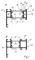
- FIG. 2A A further composite profile 21 for a window frame is shown in FIG. 2A.
- the Composite profile 21 comprises a metallic profile 22, which has insulating webs 24 and 25 is connected to a further metallic profile 23.
- the groove 26 is again undercut and includes inwardly protruding Last 28 and 30.
- the bottom of the groove 26 is through a metallic section 32 of the profile 23 and a section 33 of the insulating web 24 are formed.
- In the metallic Profile 23 is a hollow chamber 34 and one in the metallic profile 22 additional hollow chamber 35 is provided, into which fasteners can be inserted.
- the width of the thermal insulation zone formed by the insulating webs 24 and 25 is B.
- FIG 2 B is a comparable composite profile 21 'after State of the art shown.
- the composite profile 21 ' comprises a metallic profile 22 ', with insulating webs 24' and 25 'with the further metallic profile 23' connected is.
- a groove 26 ' is formed on the metallic profile 23'.
- the for Area of insulating strips 24 'and 25' available for thermal insulation has only the length B 'and is significantly smaller than in the invention Embodiment, even if the functionality of the composite profile 21 compared the composite profile 21 'of the prior art is maintained.
- FIG. 3 shows an insulating profile 40 made of plastic or a composite material, that can be used in a composite profile according to the invention.
- the insulating profile 40 comprises an insulating web 41 on the respective thickened ends 42 and 43 are formed on webs of a metal profile for a Permanent connection can be edged.
- the thickening 42 and 43 each have knurled wires 44 which provide the shear strength between Isoliersteg 41 and the respective metallic outer profile by positive locking improve.
- the groove wall 46 and the bar 47 are supported by a strut 48 extending on the side facing away from the groove, so that increased mechanical loads are also absorbed by the groove wall 46 can be.
- On the strut 48 is also a bar 49 as an attachment for molded a seal.
- FIG. 4 shows a composite profile according to the invention in the assembled state.
- a metallic profile 2 is an insulating profile with an insulating web 41 'and one Insulating web 5 connected to another metallic profile 3.
- the composite profile is part of a frame of a wing in which an insulating glass pane 55 is bordered.
- a groove 6 is provided, which as in the previous ones Embodiments has a wall through the outer wall of the metallic profile 3 is formed and on the opposite side Has wall, which is integrally formed on the insulating profile.
- the wall is on the side of the insulating profile is formed in several parts and comprises a holding section 46 ' the material of the insulating profile and an insert 51 which is edged on the insulating profile is.
- An inwardly projecting strip 52 is formed on the insert 51, so that a fitting part can be inserted captively into the groove 6.
- the wall 46 ' is supported by a strut 48' which is connected to the insulating web 41 '.
- a stop 49 'for a seal 50 is formed on the strut 48'.
- the frame is according to the state of the Technique with a metallic profile 22 'and a metallic profile 23', the are connected via insulating webs 24 'and 25'. It is also possible, an inventive composite profile according to FIG. 2A also for the window frame use.
- the size of the cavities in the metal profiles mostly from the stability requirements and the intended fasteners, like corner connector, depending. This is the area of the groove bottom, which is formed by the insulating web, relatively small. It is also possible that Extend insulating bars in other mechanical conditions. The groove dimensions and the depth of the profile can be maintained.
- the insulating webs are made of a plastic material, which is made of glass fibers or other materials can be reinforced. It is also possible to replace the deposit 51 form or insert an insert in the form of glass fiber inlays into the insulating profile or to provide other additional reinforcing means.
Abstract
Description
Die vorliegende Erfindung betrifft ein wärmegedämmtes Verbundprofil, insbesondere zur Bildung von Rahmen für Fenster, Türen, Fassadenelementen oder dergleichen, mit einem metallischen Profil auf einer ersten Seite und einem metallischen Profil auf einer gegenüberliegenden zweiten Seite, und mindestens einem Kunststoff enthaltenden Isoliersteg, der die beiden metallischen Profile unter Ausbildung einer Wärmedämmzone miteinander verbindet, wobei mindestens eine Nut zur Aufnahme eines Beschlagteiles oder Befestigungselementes vorgesehen ist.The present invention relates to a thermally insulated composite profile, in particular to form frames for windows, doors, facade elements or the like, with a metallic profile on a first side and a metallic one Profile on an opposite second side, and at least one plastic containing insulating web, which the two metallic profiles under training a thermal insulation zone connects, with at least one groove for Inclusion of a fitting part or fastener is provided.
Aus der DE 33 16 624 ist ein wärmegedämmtes Verbundprofil bekannt, das zwei Profile aus Metall aufweist, die über Isolierstäbe miteinander verbunden sind. Die Profile aus Metall weisen Nuten auf, in die Beschlagteile eingefügt werden können, sodass die Profile sich zu einem Rahmen für Fenster oder Türen zusammensetzen lassen. Zwar sorgt bei dem vorbekannten Verbundprofil die Verwendung von Isolierstegen für eine gewisse Wärmedämmung, die Isolierstege sind jedoch relativ kurz ausgebildet und schaffen daher nur eine begrenzte Wärmeisolierung. Eine Verbreiterung der Isolierstege führt zu einer Verbesserung der Wärmedämmung, führt aber auch zu einer größeren Bautiefe der Rahmenprofile selbst. Diese größere Profilbautiefe führt zu Funktionseinschränkungen der daraus gebildeten Fenster, insbesondere sind die Kleinstmaße der Fenster eingeschränkt.From DE 33 16 624 a thermally insulated composite profile is known, the two Has profiles made of metal, which are connected to one another via insulating rods. The Profiles made of metal have grooves in which fittings can be inserted, so that the profiles form a frame for windows or doors to let. With the previously known composite profile, the use of insulating webs ensures for a certain thermal insulation, but the insulating bars are relative trained short and therefore create only a limited heat insulation. A Widening of the insulating webs leads to an improvement in thermal insulation, but also leads to a greater depth of the frame profiles themselves. This greater Profile depth leads to functional restrictions of the windows formed from it, in particular, the smallest dimensions of the windows are restricted.
Es ist daher Aufgabe der vorliegenden Erfindung, ein Verbundprofil zu schaffen, das unter Beibehaltung erforderlicher mechanischer Funktionalitäten und der Profilbautiefe eine gute bzw. verbesserte Wärmedämmung besitzt.It is therefore an object of the present invention to provide a composite profile this while maintaining the required mechanical functionalities and the profile depth has good or improved thermal insulation.
Diese Aufgabe wird mit einem Verbundprofil mit den Merkmalen des Anspruches
1 gelöst.This task is accomplished with a composite profile with the features of the
Erfindungsgemäß weist das Verbundprofil eine Nut zur Aufnahme eines Beschlagteiles oder Befestigungselementes auf, deren erste Wand durch eine Außenwand oder einer Wand benachbart zu der Außenwand eines metallischen Profils und deren zweite der ersten Wand gegenüberliegende Wand an dem Isoliersteg angeformt ist. Die Nut ist somit aus einem metallischen Anteil und einem Teil am Isoliersteg gebildet, sodass die Länge des Isoliersteges vergleichsweise länger ausgebildet werden kann, was die Wärmedämmung erhöht. Die Funktionalität des Verbundprofils wird durch die Ausbildung einer solchen Nut beibehalten, da die bekannten Beschlagteile in die Nut weiter eingesetzt werden können, sodass keine mechanischen Nachteile in Kauf genommen werden müssen oder sonstige Stabilitätsprobleme auftreten. Auch die Bautiefe des Verbundprofils kann beibehalten werden.According to the invention, the composite profile has a groove for receiving a fitting part or fastener, the first wall through an outer wall or a wall adjacent to the outer wall of a metallic profile and the second wall opposite the first wall is integrally formed on the insulating web is. The groove is thus made of a metallic part and a part on the insulating web formed so that the length of the insulating web is comparatively longer can be what increases the thermal insulation. The functionality of the Composite profile is maintained by the formation of such a groove, since the known fittings can be used in the groove, so that none mechanical disadvantages have to be accepted or other stability problems occur. The depth of the composite profile can also be maintained become.
Gemäß einer bevorzugten Ausführungsform der Erfindung ist die Nut hinterschnitten ausgebildet und sowohl an der metallischen Außenwand oder einer benachbarten Wand als auch an der zweiten Wand ist jeweils eine zur Mittelebene der Nut gerichtete hervorstehende Leiste vorgesehen. Dadurch können Beschlagteile, wie Riegelstangen in das Verbundprofil eingeschoben werden und sind gegen ein Herausfallen gesichert.According to a preferred embodiment of the invention, the groove is undercut trained and both on the metal outer wall or an adjacent Wall as well as on the second wall is one to the median plane the groove directed protruding bar provided. This allows hardware components, how locking bars are inserted into the composite profile and are against secured from falling out.
Wenn der Boden der Nut teilweise aus Isoliermaterial und teilweise aus Metall gebildet ist und die Bereiche mit unterschiedlichen Materialien im wesentlichen auf einer Ebene angeordnet sind, können die Beschlagteile besonders gut in der Nut geführt werden. Kleine Höhenänderungen am Boden können meist noch kompensiert werden, allerdings sind die Beschlagteile im Querschnitt oft symmetrisch ausgebildet, sodass die Nut vorzugsweise an den Führungsflächen ebenfalls symmetrisch ausgebildet ist.If the bottom of the groove is partly made of insulating material and partly made of metal is and the areas with different materials essentially are arranged on one level, the fittings can be particularly well in the groove be performed. Small changes in height on the ground can usually still be compensated are, however, the fittings are often symmetrical in cross section, so that the groove is also preferably symmetrical on the guide surfaces is trained.
Für eine besonders stabile Führung von Beschlagteilen ist die zweite Wand der Nut verstärkt ausgebildet. Die Verstärkung kann durch eingelagerte Fasern und/oder Inlays aus einem Verstärkungsmaterial, beispielsweise Glasfasern, Metall oder anderen Werkstoffen erfolgen. Zusätzlich oder alternativ kann die zweite Wand auf der zur ersten Wand abgewandten Seite durch eine Strebe abgestützt sein, um auch hohe mechanische Belastungen aufnehmen zu können. Wenn die Strebe schräg verläuft und mit dem Isoliersteg verbunden ist, lässt sich der Isoliersteg auch als Teil eines Hohlprofils fertigen.The second wall is the groove for a particularly stable guidance of fittings increasingly trained. The reinforcement can be by embedded fibers and / or inlays made of a reinforcing material, for example glass fibers, metal or others Materials. Additionally or alternatively, the second wall can be on the side facing away from the first wall can also be supported by a strut to be able to absorb high mechanical loads. If the strut is slanted runs and is connected to the insulating web, the insulating web can also be used as Manufacture part of a hollow profile.
Für eine Verstärkung der zweiten Wand ist es auch möglich, die zweite Wand mehrteilig auszubilden. Es können auch Verstärkungsauflagen an der Nutwand vorgesehen werden, die für eine gleichmäßige Verteilung von Kräften sorgen.To reinforce the second wall, it is also possible to use the second wall to train in several parts. There can also be reinforcement pads on the groove wall be provided, which ensure an even distribution of forces.
Gemäß einer bevorzugten Ausführungsform ist das Verbundprofil als Rahmenprofil ausgebildet und jedes metallische Profil weist mindestens eine Hohlkammer zur Einfügung eines Eckverbinders auf. Dadurch lassen sich besonders stabile Rahmen für Türen oder Fenster herstellen. In die Nut, deren Abmaße beibehalten werden können, kann dann eine Riegelstange und/oder ein anderes Beschlagteil eingefügt sein, sodass der Rahmen bei hoher Stabilität auch noch eine gute Wärmedämmung besitzt.According to a preferred embodiment, the composite profile is a frame profile formed and each metallic profile has at least one hollow chamber Insertion of a corner connector. This allows particularly stable frames for doors or windows. In the groove, the dimensions of which are retained can then insert a locking bar and / or another fitting part so that the frame also provides good thermal insulation with high stability has.
Die Erfindung wird nachfolgend anhand von mehreren Ausführungsbeispielen mit Bezug auf die beigefügten Zeichnungen näher erläutert. Es zeigen:
- Figur 1 A
- eine geschnittene Querschnittsansicht durch ein erfindungsgemäßes Verbundprofil gemäß einem ersten Ausführungsbeispiel;
- Figur 1 B
- eine geschnittene Querschnittsansicht eines Verbundprofils ähnlich zu Figur 1 A gemäß dem Stand der Technik;
- Figur 2 A
- eine geschnittene Querschnittsansicht eines zweiten Ausführungsbeispiels eines erfindungsgemäßen Verbundprofils;
- Figur 2 B
- eine geschnittene Querschnittsansicht eines Verbundprofils ähnlich zu Figur 2 A gemäß dem Stand der Technik;
Figur 3- eine Querschnittsansicht eines modifizierten Isoliersteges für ein erfindungsgemäßes Verbundprofil, und
- Figur 4
- eine Querschnittsansicht eines erfindungsgemäßen Verbundprofils mit modifizierter Isolierleiste im montierten Zustand.
- Figure 1A
- a sectional cross-sectional view through an inventive composite profile according to a first embodiment;
- Figure 1B
- a sectional cross-sectional view of a composite profile similar to Figure 1 A according to the prior art;
- Figure 2A
- a sectional cross-sectional view of a second embodiment of a composite profile according to the invention;
- Figure 2B
- a sectional cross-sectional view of a composite profile similar to Figure 2 A according to the prior art;
- Figure 3
- a cross-sectional view of a modified insulating web for a composite profile according to the invention, and
- Figure 4
- a cross-sectional view of a composite profile according to the invention with modified insulating strip in the assembled state.
Ein Verbundprofil 1 für einen Flügelrahmen umfasst ein metallisches Profil 2 und
ein metallisches Profil 3, die beispielsweise aus Aluminium extrudiert sind. Zwischen
den Profilen 2 und 3 sind zwei Isolierstege 4 und 5 angeordnet, die über an
sich bekannte Befestigungstechniken mit den Profilen 2 und 3 dauerhaft verbunden
sind. An dem Metallprofil 3 und dem Isoliersteg 4 ist eine Nut 6 vorgesehen, wobei
eine erste Wand 7 der Nut 6 durch die Außenwand des Profils 3 gebildet ist. Die
Nut 6 kann auch durch eine gestrichelt dargestellte metallische Wand 16 parallel
und nahe zu der Wand 7 seitlich begrenzt sein. Auf der gegenüberliegenden Seite
ist eine zweite Wand 9 der Nut 6 am Isoliersteg 4 angeformt.A
Die Nut 6 ist hinterschnitten ausgebildet, wobei von der Außenwand 7 eine Leiste
8 und von der Wand 9 eine Leiste 10 jeweils nach innen zur Nutmitte hin hervorstehen.
Durch die Leisten 8 und 10 ist ein Beschlagteil 11 unverlierbar in der Nut 6
aufgenommen, wobei die Leiste 8 gestuft ausgebildet ist und das Beschlagteil 11
nicht direkt an der Außenwand 7 verläuft. Der Boden der Nut 6 ist teilweise durch
einen metallischen Abschnitt 12 des Profils 3 und teilweise durch einen Abschnitt
13 des Isoliersteges 4 gebildet, wobei durch das Einfassen eines verdickten Abschnitts
17 des Isoliersteges 4 mittels eines gerollten Steges 18 eine kleine Vertiefung
in dem Boden vorgesehen ist, die jedoch die Funktionsfähigkeit der Nut 6
nicht beeinträchtigt. Je nach Bedarf kann auch der Abschnitt 13 verlängert werden
und gegebenenfalls der Abschnitt 12 des metallischen Profils 3 verkürzt werden.
Die Länge des Abschnitts 12 hängt bei dem gezeigten Verbundprofil 1 von der
Größe der Hohlkammer 14 ab, die beispielsweise zur Aufnahme eines Eckverbinders
eingesetzt wird. Auf der gegenüberliegenden Seite ist am Profil 2 ebenfalls eine
Hohlkammer 15 für Befestigungsmittel vorgesehen.The
In Figur 1 B ist ein vergleichbares Verbundprofil 1 nach dem Stand der Technik
mit einem metallischen Profil 2' und einem metallischen Profil 3', die über Isolierstege
4' und 5' miteinander verbunden sind, gezeigt. An dem metallischen Profil 3'
ist eine Nut 6' vorgesehen, deren Nutwände 7' und 9' aus Metall ausgebildet sind
und die ebenfalls hinterschnitten ist, wobei nach innen hervorstehende Leisten 8'
und 10' vorgesehen sind.FIG. 1B shows a
Die Länge der Isolierstege 4' und 5' beträgt lediglich A', sodass nur eine begrenzte
Wärmeisolierung gegeben ist. Verglichen mit dem erfindungsgemäßen Ausfiihrungsbeispiel
gemäß Figur 1 A beträgt die Länge der Isolierstege 4 und 5 jeweils A
und ist deutlich länger als im Stand der Technik. Dadurch wird die Wärmedämmung
des Verbundprofils 1 verbessert, ohne dass dessen Breite vergrößert wird.
Ferner wird die Funktionalität des Verbundprofils 1 beibehalten, da sämtliche
Hohlräume 14, 15 und entsprechende Nuten 6 für den Einsatz von vorhandenen
Befestigungsmitteln und Beschlagteilen genutzt werden können.The length of the insulating webs 4 'and 5' is only A ', so that only a limited one
Thermal insulation is given. Compared to the exemplary embodiment according to the invention
According to FIG. 1A, the length of the insulating
In Figur 2 A ist ein weiteres Verbundprofil 21 für einen Blendrahmen gezeigt. Das
Verbundprofil 21 umfasst ein metallisches Profil 22, das über Isolierstege 24 und
25 mit einem weiteren metallischen Profil 23 verbunden ist. Ferner ist eine Nut 26
vorgesehen, deren eine Nutwand 27 durch eine Außenwand des metallischen Profils
23 und deren zweite Wand 29 an dem Isoliersteg 24 angeformt ist. Die Nut 26
ist wiederum hinterschnitten ausgebildet und umfasst nach innen hervorstehende
Leisten 28 und 30. Der Boden der Nut 26 wird durch einen metallischen Abschnitt
32 des Profils 23 und einen Abschnitt 33 des Isoliersteges 24 gebildet. In dem metallischen
Profil 23 ist eine Hohlkammer 34 und in dem metallischen Profil 22 eine
weitere Hohlkammer 35 vorgesehen, in die Befestigungselemente einfügbar sind.
Die Breite der durch die Isolierstege 24 und 25 gebildete Wärmedämmzone beträgt
B. A further
Demgegenüber ist in Figur 2 B ein vergleichbares Verbundprofil 21' nach dem
Stand der Technik gezeigt. Das Verbundprofil 21' umfasst ein metallisches Profil
22', das über Isolierstege 24' und 25' mit dem weiteren metallischen Profil 23'
verbunden ist. An dem metallischen Profil 23' ist eine Nut 26' ausgebildet. Der zur
Wärmedämmung zur Verfügung stehende Bereich der Isolierleisten 24' und 25'
besitzt lediglich die Länge B' und ist deutlich kleiner als bei dem erfindungsgemäßen
Ausführungsbeispiel, auch wenn die Funktionalität des Verbundprofils 21 gegenüber
dem Verbundprofil 21' des Standes der Technik beibehalten wird.In contrast, in Figure 2 B is a comparable composite profile 21 'after
State of the art shown. The composite profile 21 'comprises a
In Figur 3 ist ein Isolierprofil 40 aus Kunststoff oder einem Verbundwerkstoff gezeigt,
das bei einem erfindungsgemäßen Verbundprofil eingesetzt werden kann.
Das Isolierprofil 40 umfasst einen Isoliersteg 41 an dem endseitig jeweils Verdickungen
42 und 43 ausgebildet sind, die an Stegen eines Metallprofils für eine
Dauerhafte Verbindung eingefasst werden können. Ferner sind an den Verdickungen
42 und 43 jeweils Rändeldrähte 44 vorgesehen, die die Schubfestigkeit zwischen
Isoliersteg 41 und dem jeweiligen metallischen Außenprofil durch Formschluss
verbessern.FIG. 3 shows an insulating
An dem Isolierprofil 40 ist ein Nutboden 45 und eine sich winklig dazu erstreckende
Nutwand 46 ausgebildet, die am oberen Ende eine nach innen zu einer
Nutmitte hin gerichtete Leiste 47 umfasst. Die Nutwand 46 und die Leiste 47 sind
durch eine auf der der Nut abgewandten Seite erstreckende Strebe 48 abgestützt,
sodass durch die Nutwand 46 auch erhöhte mechanische Belastungen aufgenommen
werden können. An der Strebe 48 ist ferner noch eine Leiste 49 als Anlage für
eine Dichtung angeformt.On the insulating
In Figur 4 ist ein erfindungsgemäßes Verbundprofil im montierten Zustand gezeigt.
Ein metallisches Profil 2 ist über ein Isolierprofil mit einem Isoliersteg 41' und einem
Isoliersteg 5 mit einem weiteren metallischen Profil 3 verbunden. Das Verbundprofil
ist Bestandteil eines Rahmens eines Flügels, in dem eine Isolierglasscheibe
55 eingefasst ist. Ferner ist eine Nut 6 vorgesehen, die wie bei den vorangegangenen
Ausführungsbeispielen eine Wand aufweist, die durch die Außenwand
des metallischen Profils 3 gebildet ist und an der gegenüberliegenden Seite eine
Wand aufweist, die an dem Isolierprofil angeformt ist. Die Wand ist auf der Seite
des Isolierprofils mehrteilig ausgebildet und umfasst einen Halteabschnitt 46' aus
dem Material des Isolierprofils und eine Einlage 51, die an dem Isolierprofil eingefasst
ist. An der Einlage 51 ist eine nach innen hervorstehende Leiste 52 ausgebildet,
sodass ein Beschlagteil unverlierbar in die Nut 6 einschiebbar ist. Die Wand
46' ist über eine Strebe 48' abgestützt, die mit dem Isoliersteg 41' verbunden ist.
An der Strebe 48' ist ein Anschlag 49' für eine Dichtung 50 angeformt.FIG. 4 shows a composite profile according to the invention in the assembled state.
A metallic profile 2 is an insulating profile with an insulating web 41 'and one
Insulating
Bei dem gezeigten Ausführungsbeispiel ist der Blendrahmen gemäß dem Stand der
Technik mit einem metallischen Profil 22' und einem metallischen Profil 23', die
über Isolierstege 24' und 25' verbunden sind, ausgebildet. Es ist auch möglich,
auch für den Blendrahmen ein erfindungsgemäßes Verbundprofil gemäß Figur 2 A
einzusetzen.In the embodiment shown, the frame is according to the state of the
Technique with a
Bei den gezeigten Ausführungsbeispielen ist die Größe der Hohlräume bei den Metallprofilen meist von den Stabilitätsanforderungen und der vorgesehenen Befestigungsmittel, wie Eckverbinder, abhängig. Dadurch ist der Bereich des Nutbodens, der durch den Isoliersteg gebildet ist, relativ klein. Es ist auch möglich, die Isolierstege bei anderen mechanischen Bedingungen zu verlängern. Die Nutabmaße und die Bautiefe des Profils können jedoch beibehalten werden.In the exemplary embodiments shown, the size of the cavities in the metal profiles mostly from the stability requirements and the intended fasteners, like corner connector, depending. This is the area of the groove bottom, which is formed by the insulating web, relatively small. It is also possible that Extend insulating bars in other mechanical conditions. The groove dimensions and the depth of the profile can be maintained.
Die Isolierstege bestehen aus einem Kunststoffmaterial, das durch Glasfasern oder
andere Materialien verstärkt werden kann. Ferner ist es möglich, statt der Einlage
51 eine Einlage in Form von Glasfaser-Inlays in das Isolierprofil ein- oder anzuformen
oder andere weitere Verstärkungsmittel vorzusehen.The insulating webs are made of a plastic material, which is made of glass fibers or
other materials can be reinforced. It is also possible to replace the
Claims (10)
Applications Claiming Priority (2)
| Application Number | Priority Date | Filing Date | Title |
|---|---|---|---|
| DE10300860 | 2003-01-10 | ||
| DE10300860A DE10300860A1 (en) | 2003-01-10 | 2003-01-10 | Insulated composite profile |
Publications (3)
| Publication Number | Publication Date |
|---|---|
| EP1437478A2 true EP1437478A2 (en) | 2004-07-14 |
| EP1437478A3 EP1437478A3 (en) | 2005-04-20 |
| EP1437478B1 EP1437478B1 (en) | 2009-07-22 |
Family
ID=32478215
Family Applications (1)
| Application Number | Title | Priority Date | Filing Date |
|---|---|---|---|
| EP03028334A Expired - Lifetime EP1437478B1 (en) | 2003-01-10 | 2003-12-10 | Heat insulating composite frame member |
Country Status (5)
| Country | Link |
|---|---|
| EP (1) | EP1437478B1 (en) |
| AT (1) | ATE437286T1 (en) |
| DE (2) | DE10300860A1 (en) |
| DK (1) | DK1437478T3 (en) |
| ES (1) | ES2329455T3 (en) |
Cited By (4)
| Publication number | Priority date | Publication date | Assignee | Title |
|---|---|---|---|---|
| DE102005032176A1 (en) * | 2005-07-09 | 2007-01-11 | Hydro Building Systems Gmbh | Heat-insulated composite profile for frames of windows, doors and facades comprises one or more sealing elements extending in the plane of a frame in the central region of the frame |
| ES2302570A1 (en) * | 2005-03-18 | 2008-07-16 | Aluminios Cortizo, S.A. | Channel connection is provided between certain fixed and movable part of sheet of window or metal door in carpentry, where part of structure and framework is fixed on movable framework that is provided with multiple profiles |
| ES2303779A1 (en) * | 2007-02-01 | 2008-08-16 | Fernando Fraguas Esteban | System for the realization of metallic frames of windows and doors of sliding opening with improved thermal insulation (Machine-translation by Google Translate, not legally binding) |
| EP2532819A1 (en) * | 2011-06-06 | 2012-12-12 | Dorma GmbH + Co. KG | Door frame |
Families Citing this family (3)
| Publication number | Priority date | Publication date | Assignee | Title |
|---|---|---|---|---|
| DE102007025138A1 (en) * | 2007-05-30 | 2008-12-11 | Norsk Hydro Asa | Thermally insulated composite profile for windows, doors, facades and the like |
| DE202013105457U1 (en) | 2012-11-30 | 2013-12-05 | Akotherm Gmbh | Profile arrangement, in particular for a door or a window |
| DE102014115422A1 (en) * | 2014-10-23 | 2016-04-28 | SCHÜCO International KG | Window or door, in particular block window |
Citations (1)
| Publication number | Priority date | Publication date | Assignee | Title |
|---|---|---|---|---|
| DE3316624A1 (en) | 1983-05-06 | 1984-11-08 | SCHÜCO Heinz Schürmann GmbH & Co, 4800 Bielefeld | INSULATING ROD FOR A THERMAL INSULATED COMPOSITE PROFILE FOR WINDOWS, DOORS OR FACADES |
Family Cites Families (7)
| Publication number | Priority date | Publication date | Assignee | Title |
|---|---|---|---|---|
| DE3624849A1 (en) * | 1986-07-23 | 1988-01-28 | Schuermann & Co Heinz | WINDOW, DOOR OR FIXED GLAZING IN ANTI-BULLY VERSION |
| IT1244415B (en) * | 1990-06-07 | 1994-07-14 | Valcasa Srl | HOMOGENEOUS SERIES OF PROFILES FOR ALUMINUM FRAMES |
| DE29616617U1 (en) * | 1995-09-27 | 1996-12-05 | Hartmann & Co W | Insulated composite profile |
| DE29701026U1 (en) * | 1996-01-25 | 1997-05-07 | Hartmann & Co W | Rebate insulation profile |
| FR2760036B1 (en) * | 1997-02-21 | 1999-05-14 | Ouest Alu | WINDOW OR SLIDING WINDOW-HOLDER, WITH OPENING (S) HIDDEN |
| DE20100619U1 (en) * | 2001-01-12 | 2001-03-08 | Schueco Int Kg | Glass wing |
| DE10116049B4 (en) * | 2001-03-30 | 2016-10-06 | Ensinger Gmbh | Use of a plastic profile and method of making the same |
-
2003
- 2003-01-10 DE DE10300860A patent/DE10300860A1/en not_active Withdrawn
- 2003-12-10 DE DE50311726T patent/DE50311726D1/en not_active Expired - Lifetime
- 2003-12-10 DK DK03028334T patent/DK1437478T3/en active
- 2003-12-10 EP EP03028334A patent/EP1437478B1/en not_active Expired - Lifetime
- 2003-12-10 ES ES03028334T patent/ES2329455T3/en not_active Expired - Lifetime
- 2003-12-10 AT AT03028334T patent/ATE437286T1/en active
Patent Citations (1)
| Publication number | Priority date | Publication date | Assignee | Title |
|---|---|---|---|---|
| DE3316624A1 (en) | 1983-05-06 | 1984-11-08 | SCHÜCO Heinz Schürmann GmbH & Co, 4800 Bielefeld | INSULATING ROD FOR A THERMAL INSULATED COMPOSITE PROFILE FOR WINDOWS, DOORS OR FACADES |
Cited By (4)
| Publication number | Priority date | Publication date | Assignee | Title |
|---|---|---|---|---|
| ES2302570A1 (en) * | 2005-03-18 | 2008-07-16 | Aluminios Cortizo, S.A. | Channel connection is provided between certain fixed and movable part of sheet of window or metal door in carpentry, where part of structure and framework is fixed on movable framework that is provided with multiple profiles |
| DE102005032176A1 (en) * | 2005-07-09 | 2007-01-11 | Hydro Building Systems Gmbh | Heat-insulated composite profile for frames of windows, doors and facades comprises one or more sealing elements extending in the plane of a frame in the central region of the frame |
| ES2303779A1 (en) * | 2007-02-01 | 2008-08-16 | Fernando Fraguas Esteban | System for the realization of metallic frames of windows and doors of sliding opening with improved thermal insulation (Machine-translation by Google Translate, not legally binding) |
| EP2532819A1 (en) * | 2011-06-06 | 2012-12-12 | Dorma GmbH + Co. KG | Door frame |
Also Published As
| Publication number | Publication date |
|---|---|
| ATE437286T1 (en) | 2009-08-15 |
| DE50311726D1 (en) | 2009-09-03 |
| DK1437478T3 (en) | 2009-11-09 |
| EP1437478A3 (en) | 2005-04-20 |
| EP1437478B1 (en) | 2009-07-22 |
| ES2329455T3 (en) | 2009-11-26 |
| DE10300860A1 (en) | 2004-07-22 |
Similar Documents
| Publication | Publication Date | Title |
|---|---|---|
| EP0009652B1 (en) | Set of structural members for windows sliding vertically or horizontally | |
| EP1352134B1 (en) | Transom-mullion structure | |
| WO2009098068A1 (en) | Use of a fibre-reinforced plastic material as a reinforcement system of a profile for a window or door frame | |
| CH649809A5 (en) | ALUMINUM COMPOSITE PROFILE AND WINDOW OR DOOR CONSTRUCTION MADE WITH THIS. | |
| AT396384B (en) | METAL PROFILES FOR THE PRODUCTION OF DOORS AND WINDOWS AND SIMILAR | |
| EP1437478B1 (en) | Heat insulating composite frame member | |
| DE3517861A1 (en) | FRAME OR LEAF FRAME FOR WINDOWS OR DOORS | |
| DE3200844A1 (en) | THERMAL INSULATING COMPOSITE PROFILE | |
| AT398328B (en) | COMPOSITE PROFILE BAR WITH TWO METAL BARS AND A INSULATING BAR CONNECTING THEM AND FRAME WITH LEGS THAT HAVE ONE COMPOSITE PROFILE BAR | |
| EP1437449A2 (en) | Sealing element for a mullion-transom construction consisting of similar profiles | |
| DE202006004607U1 (en) | Frame construction for a composite of frame beams component | |
| DE3101630A1 (en) | Connection of dimensionally stable elements | |
| DE102008020988A1 (en) | Heat insulated frame profile for producing e.g. door frame, has hollow chamber formed at bar and at inner side of outer flat profile strip by side pieces for accommodating connecting elements | |
| EP3140484B1 (en) | Composite profiled section for doors, windows, or facade elements | |
| DE10028802A1 (en) | Profile for use in double glazing unit has cavities on cold and warm sides connected by narrow central section which reduces heat transfer by conduction | |
| DE19804222C2 (en) | Insulating bridge for composite profiles of window or door frames | |
| EP1457637A2 (en) | Plastic section member for door or window frames, especially for fixed frames | |
| DE202013100101U1 (en) | Thermal insulation strip and frame profile for a window, a door, a facade or a light roof | |
| CH624449A5 (en) | Device for connecting a covering frame to a base frame for windows, facades or room partitions | |
| EP3336296B1 (en) | Glass packer and window or door frame comprising same | |
| EP3150792B1 (en) | Thermally isolated profile frame system | |
| EP3591158B1 (en) | Building component | |
| DE102014112145A1 (en) | Composite profile for doors, windows or façade elements | |
| EP4102021B1 (en) | Window or door cavity profile, system with such a cavity profile and frame made from same | |
| EP4325017A1 (en) | Insulating web for connecting two profiled elements for producing a thermally insulated profile, and such a profile |
Legal Events
| Date | Code | Title | Description |
|---|---|---|---|
| PUAI | Public reference made under article 153(3) epc to a published international application that has entered the european phase |
Free format text: ORIGINAL CODE: 0009012 |
|
| AK | Designated contracting states |
Kind code of ref document: A2 Designated state(s): AT BE BG CH CY CZ DE DK EE ES FI FR GB GR HU IE IT LI LU MC NL PT RO SE SI SK TR |
|
| AX | Request for extension of the european patent |
Extension state: AL LT LV MK |
|
| PUAL | Search report despatched |
Free format text: ORIGINAL CODE: 0009013 |
|
| AK | Designated contracting states |
Kind code of ref document: A3 Designated state(s): AT BE BG CH CY CZ DE DK EE ES FI FR GB GR HU IE IT LI LU MC NL PT RO SE SI SK TR |
|
| AX | Request for extension of the european patent |
Extension state: AL LT LV MK |
|
| 17P | Request for examination filed |
Effective date: 20050708 |
|
| AKX | Designation fees paid |
Designated state(s): AT BE BG CH CY CZ DE DK EE ES FI FR GB GR HU IE IT LI LU MC NL PT RO SE SI SK TR |
|
| AXX | Extension fees paid |
Extension state: LV Payment date: 20050708 Extension state: LT Payment date: 20050708 |
|
| 17Q | First examination report despatched |
Effective date: 20080310 |
|
| GRAP | Despatch of communication of intention to grant a patent |
Free format text: ORIGINAL CODE: EPIDOSNIGR1 |
|
| GRAS | Grant fee paid |
Free format text: ORIGINAL CODE: EPIDOSNIGR3 |
|
| GRAA | (expected) grant |
Free format text: ORIGINAL CODE: 0009210 |
|
| AK | Designated contracting states |
Kind code of ref document: B1 Designated state(s): AT BE BG CH CY CZ DE DK EE ES FI FR GB GR HU IE IT LI LU MC NL PT RO SE SI SK TR |
|
| AX | Request for extension of the european patent |
Extension state: LT LV |
|
| REG | Reference to a national code |
Ref country code: GB Ref legal event code: FG4D Free format text: NOT ENGLISH |
|
| REG | Reference to a national code |
Ref country code: CH Ref legal event code: EP |
|
| REG | Reference to a national code |
Ref country code: IE Ref legal event code: FG4D |
|
| REF | Corresponds to: |
Ref document number: 50311726 Country of ref document: DE Date of ref document: 20090903 Kind code of ref document: P |
|
| REG | Reference to a national code |
Ref country code: CH Ref legal event code: NV Representative=s name: KATZAROV S.A. |
|
| REG | Reference to a national code |
Ref country code: SE Ref legal event code: TRGR |
|
| REG | Reference to a national code |
Ref country code: DK Ref legal event code: T3 |
|
| REG | Reference to a national code |
Ref country code: ES Ref legal event code: FG2A Ref document number: 2329455 Country of ref document: ES Kind code of ref document: T3 |
|
| LTIE | Lt: invalidation of european patent or patent extension |
Effective date: 20090722 |
|
| PG25 | Lapsed in a contracting state [announced via postgrant information from national office to epo] |
Ref country code: FI Free format text: LAPSE BECAUSE OF FAILURE TO SUBMIT A TRANSLATION OF THE DESCRIPTION OR TO PAY THE FEE WITHIN THE PRESCRIBED TIME-LIMIT Effective date: 20090722 |
|
| PG25 | Lapsed in a contracting state [announced via postgrant information from national office to epo] |
Ref country code: SI Free format text: LAPSE BECAUSE OF FAILURE TO SUBMIT A TRANSLATION OF THE DESCRIPTION OR TO PAY THE FEE WITHIN THE PRESCRIBED TIME-LIMIT Effective date: 20090722 |
|
| REG | Reference to a national code |
Ref country code: IE Ref legal event code: FD4D |
|
| PG25 | Lapsed in a contracting state [announced via postgrant information from national office to epo] |
Ref country code: PT Free format text: LAPSE BECAUSE OF FAILURE TO SUBMIT A TRANSLATION OF THE DESCRIPTION OR TO PAY THE FEE WITHIN THE PRESCRIBED TIME-LIMIT Effective date: 20091122 Ref country code: BG Free format text: LAPSE BECAUSE OF FAILURE TO SUBMIT A TRANSLATION OF THE DESCRIPTION OR TO PAY THE FEE WITHIN THE PRESCRIBED TIME-LIMIT Effective date: 20091022 |
|
| PG25 | Lapsed in a contracting state [announced via postgrant information from national office to epo] |
Ref country code: EE Free format text: LAPSE BECAUSE OF FAILURE TO SUBMIT A TRANSLATION OF THE DESCRIPTION OR TO PAY THE FEE WITHIN THE PRESCRIBED TIME-LIMIT Effective date: 20090722 Ref country code: RO Free format text: LAPSE BECAUSE OF FAILURE TO SUBMIT A TRANSLATION OF THE DESCRIPTION OR TO PAY THE FEE WITHIN THE PRESCRIBED TIME-LIMIT Effective date: 20090722 Ref country code: IE Free format text: LAPSE BECAUSE OF FAILURE TO SUBMIT A TRANSLATION OF THE DESCRIPTION OR TO PAY THE FEE WITHIN THE PRESCRIBED TIME-LIMIT Effective date: 20090722 Ref country code: CZ Free format text: LAPSE BECAUSE OF FAILURE TO SUBMIT A TRANSLATION OF THE DESCRIPTION OR TO PAY THE FEE WITHIN THE PRESCRIBED TIME-LIMIT Effective date: 20090722 |
|
| PLBE | No opposition filed within time limit |
Free format text: ORIGINAL CODE: 0009261 |
|
| STAA | Information on the status of an ep patent application or granted ep patent |
Free format text: STATUS: NO OPPOSITION FILED WITHIN TIME LIMIT |
|
| PG25 | Lapsed in a contracting state [announced via postgrant information from national office to epo] |
Ref country code: SK Free format text: LAPSE BECAUSE OF FAILURE TO SUBMIT A TRANSLATION OF THE DESCRIPTION OR TO PAY THE FEE WITHIN THE PRESCRIBED TIME-LIMIT Effective date: 20090722 |
|
| 26N | No opposition filed |
Effective date: 20100423 |
|
| PG25 | Lapsed in a contracting state [announced via postgrant information from national office to epo] |
Ref country code: MC Free format text: LAPSE BECAUSE OF NON-PAYMENT OF DUE FEES Effective date: 20100701 |
|
| PG25 | Lapsed in a contracting state [announced via postgrant information from national office to epo] |
Ref country code: GR Free format text: LAPSE BECAUSE OF FAILURE TO SUBMIT A TRANSLATION OF THE DESCRIPTION OR TO PAY THE FEE WITHIN THE PRESCRIBED TIME-LIMIT Effective date: 20091023 |
|
| PGFP | Annual fee paid to national office [announced via postgrant information from national office to epo] |
Ref country code: DK Payment date: 20101223 Year of fee payment: 8 |
|
| PGFP | Annual fee paid to national office [announced via postgrant information from national office to epo] |
Ref country code: SE Payment date: 20101221 Year of fee payment: 8 |
|
| PG25 | Lapsed in a contracting state [announced via postgrant information from national office to epo] |
Ref country code: LU Free format text: LAPSE BECAUSE OF NON-PAYMENT OF DUE FEES Effective date: 20091210 |
|
| PG25 | Lapsed in a contracting state [announced via postgrant information from national office to epo] |
Ref country code: HU Free format text: LAPSE BECAUSE OF FAILURE TO SUBMIT A TRANSLATION OF THE DESCRIPTION OR TO PAY THE FEE WITHIN THE PRESCRIBED TIME-LIMIT Effective date: 20100123 |
|
| PG25 | Lapsed in a contracting state [announced via postgrant information from national office to epo] |
Ref country code: TR Free format text: LAPSE BECAUSE OF FAILURE TO SUBMIT A TRANSLATION OF THE DESCRIPTION OR TO PAY THE FEE WITHIN THE PRESCRIBED TIME-LIMIT Effective date: 20090722 |
|
| PG25 | Lapsed in a contracting state [announced via postgrant information from national office to epo] |
Ref country code: CY Free format text: LAPSE BECAUSE OF FAILURE TO SUBMIT A TRANSLATION OF THE DESCRIPTION OR TO PAY THE FEE WITHIN THE PRESCRIBED TIME-LIMIT Effective date: 20090722 |
|
| REG | Reference to a national code |
Ref country code: DK Ref legal event code: EBP |
|
| REG | Reference to a national code |
Ref country code: SE Ref legal event code: EUG |
|
| PG25 | Lapsed in a contracting state [announced via postgrant information from national office to epo] |
Ref country code: SE Free format text: LAPSE BECAUSE OF NON-PAYMENT OF DUE FEES Effective date: 20111211 |
|
| PG25 | Lapsed in a contracting state [announced via postgrant information from national office to epo] |
Ref country code: DK Free format text: LAPSE BECAUSE OF NON-PAYMENT OF DUE FEES Effective date: 20120102 |
|
| REG | Reference to a national code |
Ref country code: FR Ref legal event code: PLFP Year of fee payment: 13 |
|
| REG | Reference to a national code |
Ref country code: FR Ref legal event code: PLFP Year of fee payment: 14 |
|
| PGFP | Annual fee paid to national office [announced via postgrant information from national office to epo] |
Ref country code: CH Payment date: 20161222 Year of fee payment: 14 |
|
| PGFP | Annual fee paid to national office [announced via postgrant information from national office to epo] |
Ref country code: AT Payment date: 20161219 Year of fee payment: 14 |
|
| REG | Reference to a national code |
Ref country code: FR Ref legal event code: PLFP Year of fee payment: 15 |
|
| PGFP | Annual fee paid to national office [announced via postgrant information from national office to epo] |
Ref country code: NL Payment date: 20171219 Year of fee payment: 15 |
|
| REG | Reference to a national code |
Ref country code: CH Ref legal event code: PCAR Free format text: NEW ADDRESS: AVENUE DES MORGINES 12, 1213 PETIT-LANCY (CH) |
|
| PGFP | Annual fee paid to national office [announced via postgrant information from national office to epo] |
Ref country code: ES Payment date: 20180105 Year of fee payment: 15 |
|
| REG | Reference to a national code |
Ref country code: CH Ref legal event code: PL |
|
| REG | Reference to a national code |
Ref country code: AT Ref legal event code: MM01 Ref document number: 437286 Country of ref document: AT Kind code of ref document: T Effective date: 20171210 |
|
| PG25 | Lapsed in a contracting state [announced via postgrant information from national office to epo] |
Ref country code: CH Free format text: LAPSE BECAUSE OF NON-PAYMENT OF DUE FEES Effective date: 20171231 Ref country code: AT Free format text: LAPSE BECAUSE OF NON-PAYMENT OF DUE FEES Effective date: 20171210 Ref country code: LI Free format text: LAPSE BECAUSE OF NON-PAYMENT OF DUE FEES Effective date: 20171231 |
|
| PGFP | Annual fee paid to national office [announced via postgrant information from national office to epo] |
Ref country code: IT Payment date: 20181218 Year of fee payment: 16 Ref country code: BE Payment date: 20181217 Year of fee payment: 16 Ref country code: FR Payment date: 20181218 Year of fee payment: 16 Ref country code: GB Payment date: 20181219 Year of fee payment: 16 |
|
| REG | Reference to a national code |
Ref country code: NL Ref legal event code: MM Effective date: 20190101 |
|
| PG25 | Lapsed in a contracting state [announced via postgrant information from national office to epo] |
Ref country code: NL Free format text: LAPSE BECAUSE OF NON-PAYMENT OF DUE FEES Effective date: 20190101 |
|
| PGFP | Annual fee paid to national office [announced via postgrant information from national office to epo] |
Ref country code: DE Payment date: 20191212 Year of fee payment: 17 |
|
| REG | Reference to a national code |
Ref country code: ES Ref legal event code: FD2A Effective date: 20200131 |
|
| PG25 | Lapsed in a contracting state [announced via postgrant information from national office to epo] |
Ref country code: ES Free format text: LAPSE BECAUSE OF NON-PAYMENT OF DUE FEES Effective date: 20181211 |
|
| REG | Reference to a national code |
Ref country code: BE Ref legal event code: MM Effective date: 20191231 |
|
| GBPC | Gb: european patent ceased through non-payment of renewal fee |
Effective date: 20191210 |
|
| PG25 | Lapsed in a contracting state [announced via postgrant information from national office to epo] |
Ref country code: FR Free format text: LAPSE BECAUSE OF NON-PAYMENT OF DUE FEES Effective date: 20191231 Ref country code: GB Free format text: LAPSE BECAUSE OF NON-PAYMENT OF DUE FEES Effective date: 20191210 Ref country code: IT Free format text: LAPSE BECAUSE OF NON-PAYMENT OF DUE FEES Effective date: 20191210 |
|
| PG25 | Lapsed in a contracting state [announced via postgrant information from national office to epo] |
Ref country code: BE Free format text: LAPSE BECAUSE OF NON-PAYMENT OF DUE FEES Effective date: 20191231 |
|
| REG | Reference to a national code |
Ref country code: DE Ref legal event code: R119 Ref document number: 50311726 Country of ref document: DE |
|
| PG25 | Lapsed in a contracting state [announced via postgrant information from national office to epo] |
Ref country code: DE Free format text: LAPSE BECAUSE OF NON-PAYMENT OF DUE FEES Effective date: 20210701 |