EP1437442A2 - Vorrichtung zum Führen einer laufenden, feuchten Faserstoffbahn - Google Patents
Vorrichtung zum Führen einer laufenden, feuchten Faserstoffbahn Download PDFInfo
- Publication number
- EP1437442A2 EP1437442A2 EP03104268A EP03104268A EP1437442A2 EP 1437442 A2 EP1437442 A2 EP 1437442A2 EP 03104268 A EP03104268 A EP 03104268A EP 03104268 A EP03104268 A EP 03104268A EP 1437442 A2 EP1437442 A2 EP 1437442A2
- Authority
- EP
- European Patent Office
- Prior art keywords
- web
- guide body
- fibrous web
- guide
- center line
- Prior art date
- Legal status (The legal status is an assumption and is not a legal conclusion. Google has not performed a legal analysis and makes no representation as to the accuracy of the status listed.)
- Withdrawn
Links
Images


Classifications
-
- D—TEXTILES; PAPER
- D21—PAPER-MAKING; PRODUCTION OF CELLULOSE
- D21F—PAPER-MAKING MACHINES; METHODS OF PRODUCING PAPER THEREON
- D21F1/00—Wet end of machines for making continuous webs of paper
- D21F1/36—Guiding mechanisms
- D21F1/38—Pads
-
- B—PERFORMING OPERATIONS; TRANSPORTING
- B65—CONVEYING; PACKING; STORING; HANDLING THIN OR FILAMENTARY MATERIAL
- B65H—HANDLING THIN OR FILAMENTARY MATERIAL, e.g. SHEETS, WEBS, CABLES
- B65H23/00—Registering, tensioning, smoothing or guiding webs
- B65H23/02—Registering, tensioning, smoothing or guiding webs transversely
- B65H23/022—Registering, tensioning, smoothing or guiding webs transversely by tentering devices
-
- D—TEXTILES; PAPER
- D21—PAPER-MAKING; PRODUCTION OF CELLULOSE
- D21G—CALENDERS; ACCESSORIES FOR PAPER-MAKING MACHINES
- D21G1/00—Calenders; Smoothing apparatus
- D21G1/0073—Accessories for calenders
- D21G1/0086—Web feeding or guiding devices
Definitions
- the invention relates to a device for guiding a running, moist Fibrous web, in particular a paper or cardboard web with a Guide body, which is assigned to the current fibrous web and in Stretches across the entire width of the web.
- Such a guide body is known from EP-A2-0744 388.
- the slide strip described here is fixedly arranged below the running fibrous web treated with an application medium.
- the upper side of the slide strip facing the underside of the fibrous web is rounded convexly, ie shaped in the form of a symmetrical spherical section. This symmetrical shape is maintained over the entire length of the slide rail despite the possibility of a curvature in the direction of the track.
- the invention has for its object to an improved device develop with both a contactless guidance and redirection, as well a removal and avoidance of longitudinal folds of a running, moist Fibrous web is possible.
- the object of the invention is achieved by one specified in claim 1 Device with a substantially web-wide guide body, the current fibrous web is assigned.
- the guide body has an aerodynamically shaped wing-shaped upper side facing the desired web side.
- the wing-shaped guide body is asymmetrical formed such that a convexly shaped inlet area in the form of a Circular section with a preferably bluntly increasing inlet angle and one Relatively large circular section radius is provided, to which a tangent-like part with a decreasing outlet angle.
- the guide body designed like a known aircraft wing thus able to spread the dampness respectively to achieve coated fibrous web.
- the wing-shaped Guide body with respect to an angle of attack and / or a distance from Underside of the fibrous web around an axis and / or around its center line is rotatable.
- it can also be horizontal in the transverse and longitudinal directions or be adjustable in the vertical direction.
- the guide body is different from its center line (based on its length) from its two outer sides geometrically tapered. This also makes its asymmetrical cross-sectional profile steadily reduced, resulting in particularly advantageous aerodynamic properties are reachable.
- An expedient embodiment of the invention is that the cross-sectional profiles of both side parts starting from the center line can be dimensioned differently, that is to say they can be designed in shape and size. This allows you to exert particular influence on the area of the web where the formation of wrinkles or particularly severe wrinkling is expected.
- the side parts of the guide body are opposite the Center line can be folded up or down or against each other.
- a very advantageous solution is that the side parts of the wing-shaped body are provided with end plates. This End disks are somewhat larger than the end faces around which maintain the incoming air boundary layer. That is, an unwanted one Outflow to the outside is avoided.
- the material for the guide body comes in both metal and fiber reinforced plastic, preferably GRP (glass fiber reinforced plastic in Question.
- the guide body can be manufactured in one piece, but can be manufactured be cheaper composed of individual parts.
- the guide body is particularly suitable for being used within a machine for producing and / or finishing a paper or cardboard web. It acts as an independent web guiding element, but can also be arranged in the immediate vicinity of a contactless deflecting element, for example an air turn or floating dryer. In the latter case, the towing air fed by the above-mentioned units and carried along by train is then used.
- the guide body can be used particularly advantageously in coating systems.
- the formation of longitudinal folds is particularly critical here. Therefore and for protection the freshly applied layer, the guide body is in the direction of rotation
- Fibrous web an application unit for applying a liquid up pasty medium downstream of one or both sides of the fibrous web.
- a further development of the invention also consists in that the Fiber web to the guide body, a blowing device, in particular Air blowing device is connected upstream.
- a blowing device in particular Air blowing device is connected upstream.
- Steam blowing device conceivable.
- the runtime efficiency of the Manufacturing and / or finishing, ie coating machine increased and also an improvement in product quality, such as that of coated paper elevated.
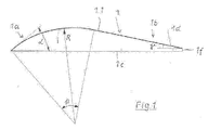
- FIG. 1 shows a guide body 1 according to the invention in cross section shown.
- the inlet area 1a - this is the area that is damp Fibrous web 2 runs -
- the guide body 1 has the shape of a Circular section with a radius R, an acute to obtuse angle ⁇ and a circular section angle ⁇ . This is followed by an elongated, tangent end portion 1b, which has an acute outlet angle ⁇ with respect to the has flat bottom 1c.
- the guide body 1 has an asymmetrical cross section Q, which means that aerodynamic phenomena of the aerofoil shape, such as a ram flow at the inlet area 1a, acceleration and formation of a negative pressure at the area 1b, are used in a special way by using the Coanda effect of the air flow ,
- the wing-shaped guide body 1 can be rotated about an axis A with respect to an angle of attack ⁇ and / or a distance a to the underside 1b of the fibrous web 2. This is shown with a curved double arrow.
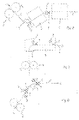
- the guide body 1 can also be tilted about its center line M (see FIG. 5 ) against the fibrous web 2.
- the guide body 1 tapers geometrically from its center line M towards its two outer sides 1d, and thus its asymmetrical cross-sectional profile Q 1-n is also continuously reduced.
- This embodiment is also shown in Figure 6 .
- a further design option can also consist in that the side parts 1 d of the guide body 1 are crossed against each other or only in each case with respect to the center line M, as shown in FIG. 7 .
- End plates 3 are also indicated in FIG . With these end disks 3 attached to the end faces 1f of the guide body 1, the flow behavior of the air boundary layer L G can be improved or maintained because it prevents the desired air boundary layer from flowing out to the outside. This ensures that the fibrous web 2 permanently passes the top 1.1 of the guide body 1 without contact.
- Metal or a fiber-reinforced material can be used as the material for the guide body 1 Plastic, preferably GRP (glass fiber plastic) can be selected.
- the guide body 1 is used in the selected example according to FIGS. 8, 9 and 10 within a coating machine following the drying section (not shown in the figures) of a machine for producing and finishing a paper or cardboard web, but could also be used in those areas where the fibrous web tends to wrinkle due to its moisture content.
- the guide body can act as an independent web guide element. In most cases, however, it is provided for arrangement in the immediate vicinity of a contactless deflecting element, for example an air turn 4 or floating dryer 5, as shown in FIGS. 8 and 10 .
- a contactless deflecting element for example an air turn 4 or floating dryer 5, as shown in FIGS. 8 and 10 .
- FIGS. 8 through 10 show that the installation of the guide body (s) 1 in the running direction L of the fibrous web 2 is arranged after a coating device 6 (so-called speedsizers or speed coaters for indirect application are shown here). Installation can only be carried out on one side of the track or on both sides of the track. The presentation and description of the special application units should be omitted here, since these are sufficiently known.
- the applied layer is a liquid up pasty application medium, such as coating color, glue or starch not damaged and the swelling of the web caused by the order with subsequent Wrinkling F can be ironed out.
- a guide body 1 alone or several Guide body can also be arranged one behind the other.
- a blowing device 7 is connected directly upstream of the guide body 1 in the running direction of the fibrous web 2. In particular, air is used for this.
- the stabilization of the web 2 and the air flow or the formation of the air boundary layer L G can be improved.
- the known Coanda effect can be used, which consists in the formation of a negative pressure pulling the web 2 in the direction of the guide body 1, without contacting the web.
- the blowing device 7 is also essentially adapted to the web width B and, as indicated in FIG. 2 , is designed as a slot nozzle 7a with a continuous slot.
- the slot nozzle is set at an angle with a profile angle ⁇ .
- FIG. 4 shows a rotating blowing roller 7b with individual blow-out openings indicated by arrows.
- FIG. 3 shows a blowing device 7 in the form of a web guiding element known per se, which can be an air turn 4, for example.
Landscapes
- Registering, Tensioning, Guiding Webs, And Rollers Therefor (AREA)
- Folding Of Thin Sheet-Like Materials, Special Discharging Devices, And Others (AREA)
- Advancing Webs (AREA)
Abstract
Description
Diese symmetrische Formgebung wird trotz vorgesehener Möglichkeit einer Wölbung in Richtung zur Bahn über die gesamte Länge der Gleitleiste beibehalten.
Infolge des erhöhten Bahnzuges entstehen Längsfalten. Diese treten vor allem an Luftumlenkeinheiten als sogenannte Omegafalten (das sind zur Umlenkseite hin gestülpte Längsschwielen) in Erscheinung.
Auch der Einsatz von sogenannten Airfoils am Auslauf von Airturns (kontaktlose Bahnumlenkeinrichtung) konnten in der Praxis nicht voll überzeugen.
die Querschnittsprofile beider von der Mittellinie ausgehender Seitenteile unterschiedlich dimensionierbar, also in Form und Größe gestaltbar sind. Dadurch kann man besonders auf jenen Bereich der Bahn Einfluss nehmen, wo das Entstehen der Faltenbildung oder eine besonders starke Faltenbildung erwartet wird.
Er ist dabei als selbständiges Bahnführungselement wirkend, kann aber auch in unmittelbarer Nähe eines kontaktlos arbeitenden Umlenkelementes, beispielsweise einem Airturn oder Schwebetrockner angeordnet sein. Im letzteren Fall wird dann die von den genannten Aggregaten gespeiste und mit der Bahn mitgeführte Schleppluft genutzt.
Er besteht darin, dass der von der Blaseinrichtung ausgehende Blasstrahl hoher Geschwindigkeit einen Unterdruck vor allem im Bereich der abfallenden Tangente des Führungskörpers erzeugt. Dadurch und im Zusammenhang mit der speziellen Tragflügel- Formgebung wird die feuchte Faserstoffbahn zum Führungskörper hin gesaugt und glättet sich dabei durch Aufschwimmen auf der Luftgrenzschicht in Querrichtung, so dass bestehende Bahn-Längsfalten ausgeglichen werden oder gar nicht erst entstehen können.
einen erfindungsgemäßen Führungskörper im Querschnitt
den Führungskörper gem. Fig. 1 in Zusammenwirkung mit jeweils einer Blaseinrichtung
die Draufsicht auf den Führungskörper gem. Fig.1
Einbaumöglichkeiten innerhalb einer Streichmaschine
Dadurch wird gewährleistet, dass die Faserstoffbahn 2 auf Dauer kontaktlos die Oberseite 1.1 des Führungskörpers 1 passiert.
Dabei kann der Einbau nur an einer Bahnseite oder aber auch an beiden Bahnseiten erfolgen.
Auf die Darstellung und Beschreibung der speziellen Auftragsaggregate soll hier verzichtet werden, da diese hinlänglich bekannt sind.
Claims (12)
- Vorrichtung zum Führen einer laufenden, feuchten Faserstoffbahn, insbesondere einer Papier- oder Kartonbahn
mit
einem Führungskörper (1), der der laufenden Faserstoffbahn (2) zugeordnet ist und der sich im wesentlichen über die gesamte Bahnbreite (B) erstreckt,
dadurch gekennzeichnet, dass
der Führungskörper (1) eine aerodynamisch geformte, tragflügelförmige Oberseite (1.1) aufweist und damit in der Lage ist, eine Breitstreckwirkung auf die dem Führungskörper (1) zugewandte Bahnseite derart zu erzielen, dass Längsfalten (F) in der Faserstoffbahn (2) beseitig- oder vermeidbar sind. - Vorrichtung nach Anspruch 1,
dadurch gekennzeichnet, dass
der tragflügelförmige Führungskörper (1) einen asymmetrischen Querschnitt (Q) aufweist und hinsichtlich eines Anstellwinkels (δ) und/oder eines Abstandes (a) zur Unterseite (1 b) der Faserstoffbahn (2) um eine Achse (A) und/oder um seine Mittellinie (M) drehbar und/oder horizontal und/oder vertikal verstellbar ist. - Vorrichtung nach Anspruch 1 und 2,
dadurch gekennzeichnet, dass
der Führungskörper (1) sich von seiner Mittellinie (M) aus nach seinen beiden Außenseiten (1 d) hin geometrisch verjüngt und sich damit auch sein asymmetrisches Querschnittsprofil (Q1-n) stetig verringert. - Vorrichtung nach Anspruch 1 bis 3,
dadurch gekennzeichnet, dass
die Querschnittsprofile (Q1-n) beider von der Mittellinie (M) ausgehenden Seiten in Größe und Form unterschiedlich gestaltbar sind. - Vorrichtung nach Anspruch 1 bis 4,
dadurch gekennzeichnet, dass
die Außenseiten (1 d) des Führungskörpers (1) gegenüber der Mittellinie (M) und/oder gegeneinander verschränkbar sind. - Vorrichtung nach Anspruch 1 bis 5,
dadurch gekennzeichnet, dass
die Außenseiten (1d) mit stirnseitigen Endscheiben (3) versehen sind. - Vorrichtung nach Anspruch 1 bis 6,
dadurch gekennzeichnet, dass
als Material für den Führungskörper (1) Metall oder ein faserverstärkter Kunststoff, vorzugsweise GFK gewählt ist. - Vorrichtung nach Anspruch 1 bis 7,
dadurch gekennzeichnet, dass
der Führungskörper (1) innerhalb einer Maschine zur Herstellung und/oder Veredelung einer Papier- oder Kartonbahn eingesetzt ist und dabei als selbständiges Bahnführungselement wirkt oder in unmittelbarer Nähe eines kontaktlos arbeitenden Umlenkelementes, beispielsweise einem Airturn (4) oder einem Schwebetrockner (5) angeordnet ist. - Vorrichtung nach Anspruch 8,
dadurch gekennzeichnet, dass
der Führungskörper (1) in Laufrichtung (L) der Faserstoffbahn (2) einer Auftragsvorrichtung (6) zum Auftragen eines flüssigen bis pastösen Mediums auf eine oder beider Seiten der Faserstoffbahn (2) nachgeordnet ist. - Vorrichtung nach Anspruch 8 und 9,
dadurch gekennzeichnet, dass
ein Führungskörper (1) allein oder mehrere Führungskörper (1) hintereinander auf einer oder beiden Bahnseiten angeordnet ist bzw. sind. - Vorrichtung nach einem oder mehreren der vorangehenden Ansprüche 1 bis 10,
dadurch gekennzeichnet, dass
in Laufrichtung (L) der Faserstoffbahn (2) dem Führungskörper (1) eine Blaseinrichtung (7), insbesondere Luftblaseinrichtung, zur Erzeugung des an sich bekannten Coanda-Effektes unmittelbar vorgeschaltet ist. - Vorrichtung nach Anspruch 11,
dadurch gekennzeichnet, dass
die Blaseinrichtung (7) im Wesentlichen bahnbreit ausgebildet und als eine Schlitzdüse (7a) oder eine Blaswalze (7b) oder einem sonstigen Bahnführungselement, wie einem Airturn (4) gestaltet ist.
Applications Claiming Priority (2)
| Application Number | Priority Date | Filing Date | Title |
|---|---|---|---|
| DE2002154777 DE10254777A1 (de) | 2002-11-22 | 2002-11-22 | Vorrichtung zum Führen einer laufenden, feuchten Faserstoffbahn |
| DE10254777 | 2002-11-22 |
Publications (2)
| Publication Number | Publication Date |
|---|---|
| EP1437442A2 true EP1437442A2 (de) | 2004-07-14 |
| EP1437442A3 EP1437442A3 (de) | 2006-08-02 |
Family
ID=32240345
Family Applications (1)
| Application Number | Title | Priority Date | Filing Date |
|---|---|---|---|
| EP03104268A Withdrawn EP1437442A3 (de) | 2002-11-22 | 2003-11-19 | Vorrichtung zum Führen einer laufenden, feuchten Faserstoffbahn |
Country Status (2)
| Country | Link |
|---|---|
| EP (1) | EP1437442A3 (de) |
| DE (1) | DE10254777A1 (de) |
Cited By (1)
| Publication number | Priority date | Publication date | Assignee | Title |
|---|---|---|---|---|
| DE202012012256U1 (de) | 2011-12-22 | 2013-02-27 | Pegas Nonwovens S.R.O. | Einrichtung zur Behandlung eines Vliesstoffs |
Families Citing this family (1)
| Publication number | Priority date | Publication date | Assignee | Title |
|---|---|---|---|---|
| FI128445B (fi) | 2017-03-31 | 2020-05-15 | Runtech Systems Oy | Menetelmä päänvientinauhan kuljettamiseksi kuiturainakoneessa rakenneryhmältä toiselle sekä laitteisto että sen käyttö |
Family Cites Families (9)
| Publication number | Priority date | Publication date | Assignee | Title |
|---|---|---|---|---|
| US3106365A (en) * | 1961-02-27 | 1963-10-08 | Beloit Eastern Corp | Compound bowed d bar spreader |
| US4186860A (en) * | 1978-10-16 | 1980-02-05 | Crown Zellerbach Corporation | Web threading system |
| US4697728A (en) * | 1986-01-16 | 1987-10-06 | Sawyer Sr William D | Paper web spreading shoe |
| DE4110875A1 (de) * | 1991-04-04 | 1992-10-08 | Voith Gmbh J M | Trockenpartie |
| DE9109313U1 (de) * | 1991-07-27 | 1991-09-26 | J.M. Voith Gmbh, 7920 Heidenheim | Vorrichtung zum Führen einer laufenden Bahn |
| DE4439639C1 (de) * | 1994-11-07 | 1996-05-02 | Altan Dr Ing Bassa | Vorrichtung zur berührungslosen Richtungsänderung einer laufenden Materialbahn |
| DE29508421U1 (de) * | 1995-05-20 | 1995-09-14 | Voith Sulzer Papiermaschinen GmbH, 89522 Heidenheim | Stationäre Gleitleiste |
| US5967457A (en) * | 1996-07-23 | 1999-10-19 | Thermo Wisconsin, Inc. | Airfoil web stabilization and turning apparatus and method |
| US6328852B1 (en) * | 1999-08-24 | 2001-12-11 | Kimberly-Clark Worldwide, Inc. | Method and apparatus for improving stability of moving webs |
-
2002
- 2002-11-22 DE DE2002154777 patent/DE10254777A1/de not_active Withdrawn
-
2003
- 2003-11-19 EP EP03104268A patent/EP1437442A3/de not_active Withdrawn
Cited By (1)
| Publication number | Priority date | Publication date | Assignee | Title |
|---|---|---|---|---|
| DE202012012256U1 (de) | 2011-12-22 | 2013-02-27 | Pegas Nonwovens S.R.O. | Einrichtung zur Behandlung eines Vliesstoffs |
Also Published As
| Publication number | Publication date |
|---|---|
| DE10254777A1 (de) | 2004-06-03 |
| EP1437442A3 (de) | 2006-08-02 |
Similar Documents
| Publication | Publication Date | Title |
|---|---|---|
| EP1208917B1 (de) | Vorhang-Auftragsvorrichtung | |
| DE3504820A1 (de) | Vorrichtung in der trockenpartie einer papiermaschine | |
| DE1474239C3 (de) | Verfahren und Einrichtung zur Stabilisierung der Lage unter Wirkung eines Blasmittels schwebend geführter Warenbahnen | |
| DE10012344A1 (de) | Vorhang-Auftragsverfahren | |
| DE3630570C2 (de) | Verfahren und Vorrichtung in einem Papiermaschinen-Zylindertrockner mit Zweisiebführung | |
| DE102022105518A1 (de) | Auftragsdüse, Auftragswerk und Verfahren | |
| DE69430837T2 (de) | Verfahren und Vorrichtung zur Beschichtung eines laufenden Bahnes | |
| EP2157240B1 (de) | Vorhang-Auftragsmaschine | |
| DE102022105510A1 (de) | Auftragsdüse, Auftragswerk und Verfahren | |
| WO2004074148A2 (de) | Vorrichtung zum führen einer laufenden faserstoffbahn | |
| EP0744366B1 (de) | Vorrichtung zum Führen einer Faserstoffbahn mit einer stationären Gleitleiste | |
| DE69400357T2 (de) | Leimpresse | |
| EP0643168B1 (de) | Vorrichtung zum Streichen einer Papierbahn | |
| WO2002004744A1 (de) | Auftragsvorrichtung | |
| DE10254777A1 (de) | Vorrichtung zum Führen einer laufenden, feuchten Faserstoffbahn | |
| DE102004003899A1 (de) | Vorrichtung zum Führen einer laufenden Faserstoffbahn | |
| DE102023106574A1 (de) | Auftragsdüse, Former und Verwendung | |
| DE3715554C2 (de) | ||
| EP1295973B1 (de) | Anlage und Verfahren zum Transportieren von textilen Flächengebilden | |
| EP1432525A2 (de) | Auftragsvorrichtung | |
| DE102005041649A1 (de) | Auftragsvorrichtung | |
| EP4328376B1 (de) | Schrägsiebformer | |
| AT526630B1 (de) | Behandlungssystem zur Behandlung einer Faserbahn | |
| DE4334468C2 (de) | Verfahren und Vorrichtung zur Stabilisierung einer laufenden Bahn | |
| AT12262U1 (de) | Verfahren bei der behandlung einer gestrichenen/oberflächengeleimten papier- und kartonbahn in einem nachbehandlungsteil für eine papier- oder kartonmaschine sowie ein nachbehandlungsteil für eine papier- oder kartonmaschine |
Legal Events
| Date | Code | Title | Description |
|---|---|---|---|
| PUAI | Public reference made under article 153(3) epc to a published international application that has entered the european phase |
Free format text: ORIGINAL CODE: 0009012 |
|
| AK | Designated contracting states |
Kind code of ref document: A2 Designated state(s): AT BE BG CH CY CZ DE DK EE ES FI FR GB GR HU IE IT LI LU MC NL PT RO SE SI SK TR |
|
| AX | Request for extension of the european patent |
Extension state: AL LT LV MK |
|
| PUAL | Search report despatched |
Free format text: ORIGINAL CODE: 0009013 |
|
| AK | Designated contracting states |
Kind code of ref document: A3 Designated state(s): AT BE BG CH CY CZ DE DK EE ES FI FR GB GR HU IE IT LI LU MC NL PT RO SE SI SK TR |
|
| AX | Request for extension of the european patent |
Extension state: AL LT LV MK |
|
| RAP1 | Party data changed (applicant data changed or rights of an application transferred) |
Owner name: VOITH PATENT GMBH |
|
| 17P | Request for examination filed |
Effective date: 20070202 |
|
| AKX | Designation fees paid |
Designated state(s): AT BE BG CH CY CZ DE DK EE ES FI FR GB GR HU IE IT LI LU MC NL PT RO SE SI SK TR |
|
| 17Q | First examination report despatched |
Effective date: 20090330 |
|
| STAA | Information on the status of an ep patent application or granted ep patent |
Free format text: STATUS: THE APPLICATION IS DEEMED TO BE WITHDRAWN |
|
| 18D | Application deemed to be withdrawn |
Effective date: 20090502 |