EP1437193A1 - Frictional agitating connection device and robot with the device - Google Patents
Frictional agitating connection device and robot with the device Download PDFInfo
- Publication number
- EP1437193A1 EP1437193A1 EP02801584A EP02801584A EP1437193A1 EP 1437193 A1 EP1437193 A1 EP 1437193A1 EP 02801584 A EP02801584 A EP 02801584A EP 02801584 A EP02801584 A EP 02801584A EP 1437193 A1 EP1437193 A1 EP 1437193A1
- Authority
- EP
- European Patent Office
- Prior art keywords
- rotating tool
- rotation
- axis
- shaft
- holding means
- Prior art date
- Legal status (The legal status is an assumption and is not a legal conclusion. Google has not performed a legal analysis and makes no representation as to the accuracy of the status listed.)
- Granted
Links
Images




Classifications
-
- B—PERFORMING OPERATIONS; TRANSPORTING
- B23—MACHINE TOOLS; METAL-WORKING NOT OTHERWISE PROVIDED FOR
- B23K—SOLDERING OR UNSOLDERING; WELDING; CLADDING OR PLATING BY SOLDERING OR WELDING; CUTTING BY APPLYING HEAT LOCALLY, e.g. FLAME CUTTING; WORKING BY LASER BEAM
- B23K20/00—Non-electric welding by applying impact or other pressure, with or without the application of heat, e.g. cladding or plating
- B23K20/12—Non-electric welding by applying impact or other pressure, with or without the application of heat, e.g. cladding or plating the heat being generated by friction; Friction welding
- B23K20/122—Non-electric welding by applying impact or other pressure, with or without the application of heat, e.g. cladding or plating the heat being generated by friction; Friction welding using a non-consumable tool, e.g. friction stir welding
- B23K20/1245—Non-electric welding by applying impact or other pressure, with or without the application of heat, e.g. cladding or plating the heat being generated by friction; Friction welding using a non-consumable tool, e.g. friction stir welding characterised by the apparatus
- B23K20/125—Rotary tool drive mechanism
-
- B—PERFORMING OPERATIONS; TRANSPORTING
- B23—MACHINE TOOLS; METAL-WORKING NOT OTHERWISE PROVIDED FOR
- B23K—SOLDERING OR UNSOLDERING; WELDING; CLADDING OR PLATING BY SOLDERING OR WELDING; CUTTING BY APPLYING HEAT LOCALLY, e.g. FLAME CUTTING; WORKING BY LASER BEAM
- B23K20/00—Non-electric welding by applying impact or other pressure, with or without the application of heat, e.g. cladding or plating
- B23K20/12—Non-electric welding by applying impact or other pressure, with or without the application of heat, e.g. cladding or plating the heat being generated by friction; Friction welding
- B23K20/122—Non-electric welding by applying impact or other pressure, with or without the application of heat, e.g. cladding or plating the heat being generated by friction; Friction welding using a non-consumable tool, e.g. friction stir welding
- B23K20/1245—Non-electric welding by applying impact or other pressure, with or without the application of heat, e.g. cladding or plating the heat being generated by friction; Friction welding using a non-consumable tool, e.g. friction stir welding characterised by the apparatus
-
- B—PERFORMING OPERATIONS; TRANSPORTING
- B23—MACHINE TOOLS; METAL-WORKING NOT OTHERWISE PROVIDED FOR
- B23K—SOLDERING OR UNSOLDERING; WELDING; CLADDING OR PLATING BY SOLDERING OR WELDING; CUTTING BY APPLYING HEAT LOCALLY, e.g. FLAME CUTTING; WORKING BY LASER BEAM
- B23K20/00—Non-electric welding by applying impact or other pressure, with or without the application of heat, e.g. cladding or plating
- B23K20/12—Non-electric welding by applying impact or other pressure, with or without the application of heat, e.g. cladding or plating the heat being generated by friction; Friction welding
- B23K20/122—Non-electric welding by applying impact or other pressure, with or without the application of heat, e.g. cladding or plating the heat being generated by friction; Friction welding using a non-consumable tool, e.g. friction stir welding
- B23K20/1265—Non-butt welded joints, e.g. overlap-joints, T-joints or spot welds
Definitions
- the present invention relates to a friction stir welding apparatus for welding two or more over-wrapped work pieces together by pressing a rotating tool against an outermost work piece to soften the work pieces by frictional heat and then to stir the molten material of the work pieces, and relates to a robot equipped with the apparatus.
- Fig. 7 is a view showing a configuration of a spot welding gun 1, which is a conventional friction stir welding apparatus, utilizing the technologies of the above disclosures.
- This spot welding gun 1 comprises a rotating tool 3 having a pin 2 at a tip end thereof, and presses the rotating tool 3 against one of work pieces (not shown) while rotating the rotating tool 3 at high speed, and then softens and stirs a joining part of the work pieces with the pin 2 with the frictional heat by rotation, and thus joins the work pieces together.
- the spot welding gun 1 also comprises a rotational movement drive source 4 for rotating the rotating tool 3 generally oriented downward about an axis-of-rotation L thereof at a high-speed, and a linear movement drive source 5 for linearly moving the rotating tool 3 along the axis-of-rotation L.
- the rotating tool 3 is fixed to the lower end of a rotational shaft 7 being rotated about the axis-of-rotation L by the rotational movement drive source 4.
- This rotating tool 3 is limited its linear movement along the axis-of-rotation L, and is held by a header 10 so as to be rotatable about the axis-of-rotation L.
- a pressurizing shaft 6 is provided so as to surround the rotational shaft 7 and the header 10 is fixed to the lower end of this pressurizing shaft 6.
- An outer peripheral of the pressurizing shaft 6 is formed to be an outer threaded portion onto which a nut member 11 is threadedly engaged. These are implemented by for example, a ball-screw mechanism. As the nut member 11 is rotated by the linear movement drive source 5, the pressurizing shaft 6 moves upward or downward along the axis-of-rotation L. Since the rotating tool 3 is rotatably supported through the header 10 at the lower end of the pressurizing shaft 6, the rotation of the rotational shaft 7 by the rotational movement drive source 4 causes a high-speed rotation of the rotating tool 3 as well as the linear movement.
- the above mechanism is attached to the main frame 14.
- a gun arm 12 is fixed extending downward from to the main frame 14.
- the lower portion of the gun arm 12 is bent and a receiving portion 13 which opposes the rotating tool 3 is provided at a tip end of the lower portion.
- the pressurizing shaft 6 which surrounds the rotational shaft 7 is supported by the main frame 14 through the nut member 11.
- the shaft is stably supported.
- the pressurizing shaft 6 is lowered, it will be difficult to stably support the rotating tool 3 with high-speed rotation since a distance between the supporting position of the pressurizing shaft 6 and the headers 10 becomes large. Meanwhile, at the time of welding, the work pieces will be pressurized while the distance of the supporting position and the rotating tool 3 becomes large.
- a pressure force is only transmitted through the hollow pressurizing shaft 6, it is difficult to stably transmit the pressure force with the thin pressurizing shaft.
- the purpose of the present invention is to provide a friction stir welding apparatus capable of stably applying a pressure force without enlarging the size of the whole apparatus, and to provide a robot equipped thereof.
- the friction stir welding apparatus in which a rotating tool with high-speed rotation is moved along the axis-of-rotation of the rotating tool, a tip portion of the rotating tool is pressed against two or more over-wrapped work pieces, a contact portion of the work pieces with the tip portion of the rotating tool is forced to be soften and stirred by frictional heat generated by the rotating tool, and thus the work pieces are welded together.
- the friction stir welding apparatus comprises a rotational shaft extending along the axis-of-rotation, a rotational movement drive source for rotating the rotational shaft, a hollow surrounding shaft surrounding the rotational shaft, rotating tool holding means for rotatably holding at least one of the rotating tool or the rotating shaft and being movably supported in the axis-of-rotation, and a linear movement drive source for linearly moving the rotating tool along the axis-of-rotation by linearly moving the rotating tool holding means along the axis-of-rotation.
- the rotating tool integrally includes a pin which forms said tip portion and a shoulder portion which has a larger diameter than the pin and which is connected with the pin at one end so that the pin protrudes therefrom.
- the rotational shaft is supported for example, telescopically by a hollow shaft ("a surrounding shaft" in the present invention) surrounding the rotational shaft which generally corresponds to the conventional pressurizing shaft.
- a surrounding shaft supports the rotational shaft so as to permit both a linear movement along the axis-of-rotation and a rotational movement about the axis-of-rotation.
- the rotational shaft having the rotating tool at a tip end thereof is held by the rotating tool holding means integrally rotatable with the rotating tool in the position of the rotating tool and/or the rotational shaft.
- the rotating tool holding means is linearly movable along the axis-of-rotation, and thus the holding position of for example the frame main to which the rotating tool holding means is linearly movable along the axis-of-rotation with the rotating tool (and the rotational shaft). Therefore, the relative position between the above-mentioned holding position and the rotating tool remains unchanged
- the present invention since it is not necessary to choose a surrounding shaft (i.e., corresponding to the conventional pressurizing shaft) with a larger diameter surrounding the rotational shaft, it is not necessary to enlarge the size of the whole apparatus. Moreover, according to the present invention, since it does not apply a pressure force only by the hollow surrounding shaft but also apply a pressure force with the whole rotating tool holding means to hold the rotating tool and its rotational shaft, it can increase the pressure force and further it can stably apply the pressure force.
- friction stir welding apparatus may be independently or integrally provided with the rotating tool.
- the above-mentioned rotating tool holding means may be constituted so that it may detachably hold the rotating tool, and this may be implemented by a header having for example a collet chuck.
- the rotating tool holding means applies a pressure force by the whole, it is preferably formed from a rigid material.
- one structure for supporting the above-mentioned rotating tool holding means linearly movable along the axis-of-rotation is a linear guide, for example.
- other structures may also be utilized as a matter of course.
- the rotating tool holding means may be constituted so that for example the linear movement drive source rotates the surrounding shaft, and the rotating tool holding means is provided with a hole into which the surrounding shaft is inserted. Threaded portions are formed in the inner peripheral surface of the hole and the outer peripheral surface of the surrounding shaft, respectively, which threadedly engage each other. According to this simple structure, a rotational movement of the surrounding shaft by the linear movement drive source is securely converted into a linear movement of the rotating tool holding means.
- the rotating tool holding means is made to be such a shape that its lateral cross section with respect to the axis surrounds the axis-of-rotation (for example, a C-shape or a channel-shape), It can cover movable parts of the above-mentioned apparatus, and then can attain high rigidity and provide a reliable pressure force.
- the rotating tool utilized in the friction stir welding apparatus is preferably formed such that a surface of the shoulder portion on the protruding side of the pin is more recessed as being closer to the base end portion of the pin.
- a surface of the shoulder portion on the protruding side of the pin is more recessed as being closer to the base end portion of the pin.
- Fig. 1 is a sectional side elevation view showing a configuration of a spot welding gun 20 which is one form of embodiments of a friction stir welding apparatus of the present invention.
- Fig. 2 is a front view of the spot welding gun 20 of Fig. 1.
- the spot welding gun 20 is mounted to for example a six-freedom-multiple-joint type robot's wrist part, and is utilized for carrying out a spot welding of the work pieces (such as aluminum bodies of an automobile, etc.) made of aluminum alloy by a friction stir welding.
- the spot welding gun 20 is attached to the wrist part of the robot 100 with a rotating tool 22.
- the spot welding gun 20 comprises a main frame 29 for supporting the rotating tool 22 so as to apply a pressure force to the rotating tool 22, a gun arm 21 attached to the main frame 29, a linear-movement motor (i.e., a linear movement drive source) 24 for linearly moving the rotating tool 22, and a rotational movement motor (i.e., a rotational movement drive source) 25 for rotating the rotating tool 22.
- a linear-movement motor i.e., a linear movement drive source
- a rotational movement motor i.e., a rotational movement drive source
- the rotating tool 22 has a truncated-cone shape and is supported by the main frame 29 rotatable about the axis-of-rotation L which is the center line of the truncated-cone shape, while which tip side is oriented downward.
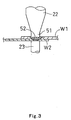
- a circular-pillar-shaped shoulder portion 51 is formed in the tip end portion of the rotating tool 22, and a circular-pillar-shaped pin 52 which has its axial center line coaxial with the axis-of-rotation L protrudes downwardly from the lower end surface of the shoulder portion 51.
- the rotating tool 22 is adapted to be movable upwardly and downwardly along the axis-of-rotation L.
- the linear movement motor 24 and the rotational movement motor 25 each of which is implemented by a servo motor are fixed to the upper part of the main frame 29.
- the gun arm 21 fixed to the main frame 29 is bent approximately in the shape of the letter "L", a receiving portion 23 is fixed to the tip end portion of the gun arm 21.
- the receiving portion 23 has generally a circular-pillar shape, and is arranged such that its upper end surface opposes to the tip end of the rotating tool 22 coaxial with the axis-of-rotation L.
- the spot welding gun 20 is aligned by the robot 100 so that the receiving portion 23 is positioned right under a welding point of the work pieces W1 and W2 being over-wrapped.
- the rotating tool 22 is rotated by the rotational movement motor 25 at a high speed (for example, 2500rpm-3000rpm) and is moved downwardly by the linear movement motor 24, the gun 20 is moved upwardly by the robot 100 and thus the pin 52 at the tip end of the rotating tool 22 and the receiving portion 23 simultaneously contact the work pieces W1 and W2.
- the tip end of the rotating tool 22 is provided with the shoulder portion 51 of which lower end surface is dented toward its center and the pin 52 protrudes from its center. That is, the lower end surface of the shoulder portion 51 has a shape such that its edge portion is extended downward. Therefore, the edge portion is mainly pressed against the work piece surface when applying a pressure, and it can stir effectively.
- the linear movement motor 24 is reversed to move the rotating tool 22 upwardly.
- a predetermined pressure force for example, several 100 kg/cm2
- a predetermined time for example, several seconds
- the rotational shaft 26 is coupled with the rotating tool 22.
- the rotational shaft 26 is a spline shaft extended upwardly from the rotating tool 22 along the axis-of-rotation L, and a pulley 48 is fitted on a lower position of the rotational shaft 26.
- the pulley 48 transmits a torque to the rotational shaft 26 while it permits a movement of the rotational shaft 26 along axis-of-rotation L but prevents a rotation of the rotational shaft 26 about the axis-of-rotation L, by the spline formed on the inside surface thereof.
- This pulley 48 is supported by the main frame 29 rotatably about the axis-of-rotation L through bearings 50.
- a pulley 46 is also fixed on the output shaft of the rotational movement motor 25 which is fixed downwardly to the main frame 29 and a belt 47 is wrapped around the pulleys 46 and 48. Thus, by rotating the rotational movement motor 25, the rotating tool 22 is rotated.
- a hollow surrounding shaft 27 is provided in the upper part of the rotational shaft 26 so as to surround the rotational shaft 26.
- the surrounding shaft 27 is supported by bearings 31 and 32 (only one bearing 32 is shown in Fig. 2) at both upper and lower ends, respectively, rotatably about the axis-of-rotation L.
- the rotational shaft 26 inserted in the surrounding shaft 27 is protruded from the lower end of the surrounding shaft 27 downwardly.
- a pulley 60 is fixed to the upper end part of the surrounding shaft 27.
- a pulley 61 is also fixed to the output shaft of the linear movement motor 24 fixed to the gun arm 21 upwardly on the rotational movement motor 25 and a belt 62 is wrapped around the pulley 61 and the pulley 60 which is fixed to the surrounding shaft 27.
- the surrounding shaft 27 can be rotated about the axis-of-rotation L.
- An outer threaded portion is formed around the outer periphery of the surrounding shaft 27 and a nut member 53 is threadedly engaged with the nut member 53.
- the nut member 53 is located between the bearings 31 and 32 which support the surrounding shaft 27 at both upper and lower ends.
- the surrounding shaft 27 and the nut member 53 is implemented by for example, a ball-screw mechanism.
- a linear guide 55 is fixed to the gun arm 21 so that it opposes the surrounding shaft 27 and is oriented in parallel with the axis-of-rotation L, and the nut member 53 is supported by the linear guide 55 so as to be linearly guided along the axis-of-rotation L.
- the rotating tool 22 is rotatably attached to a header 40.
- the header 40 holds the rotating tool 22 rotatably about the axis-of-rotation L through bearings 65 and 66.
- the header 40 and the nut member 53 are connected through a bracket 70
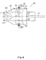
- Fig. 5 is a horizontal sectional view taken along the line A-A in Fig. 2.
- the bracket 70 is extended along the axis-of-rotation L, and is generally a C-shaped in cross-section such that it surrounds the axis-of-rotation L.
- the nut member 53, the surrounding shaft 27, and the header 40 are arranged in this order from top. Since the bracket 70 is made of high rigidity material, such as iron, carbon steel, or stainless steel and is generally a C-shaped in cross-section having the axis-of-rotation L as its center, the applied pressure force by the nut member 53 can be securely transmitted to the header 40.
- the pressure force of the linear movement motor 24 is directly transmitted to the header 40 which holds the rotating tool 22 through the bracket 70.
- the pressure force applied to the rotating tool was transmitted from the pressurizing shaft coupled with the header. That is, the pressure force is transmitted only from the hollow shaft, and the pressurizing shaft itself is supported only by the main frame through the bearings. Therefore, when the rotating tool is at the uppermost position and the distance between the bearings which support the pressurizing shaft and the rotating tool is small, the rotating tool can be stably supported. However, when the rotating tool is lowered and the distance between the rotating tool and the bearings which support the pressurizing shaft becomes large, it will be difficult to stably support the rotating tool. Furthermore, in order to apply a pressure force by the hollow pressurizing shaft in this state, the diameter of the pressurizing shaft have to be sufficiently enlarged and thus the whole apparatus needed to be enlarged.
- the surrounding shaft 27 itself does not move and does not have a structure of transmitting a pressure force by the surrounding shaft 27.
- the nut member 53 moves in accordance with the rotation of the surrounding shaft 27 and this movement of the nut member 53 is transmitted to the header 40 through the bracket 70. That is, since the pressure force is transmitted by the rigid and generally C-shaped bracket 70, it can transmit a larger pressure force, the diameter of the surrounding shaft 27 does not need to be enlarged, and the whole apparatus can be constituted compactly.
- the header 40 is provided with a holding portion 80 for detachably holding the rotating tool 22 and an outer frame 81 for rotatably supporting the holding portion 80.
- a collet chuck 71 is provided in the lower end portion of the holding portion 80 and the upper part of the rotating tool 22 is integrally formed with the circular-pillar-shaped coupling shaft 72.
- the collet chuck 71 into which the coupling shaft 72 is inserted includes a fastening member 73 which is branched in a plurality of parts and a nut attached over the fastening member 73.
- the coupling shaft 72 of the rotating tool 22 is inserted in the fastening member 73, and then the nut 74 is fastened.
- fastening member 73 fasten the coupling shaft 72 and the rotating tool 22 is fixed to the holding portion 80.
- the nut 74 is just loosened and removed.
- the rotating tool 22 can be easily maintained and replaced since the rotating tool 22 is constituted to be easily detachable as described above.
- the holding portion 80 is supported by an outer frame 81 through a pair of bearings 65 and 66 rotatably about the axis-of-rotation L.
- the outer frame 81 of the header 40 and the bracket 70 are fastened together by bolts 82.
- the work pieces were made from an aluminum alloy
- the present invention is not limited to the material and other metals or synthetic resins may be applied.
- the pressure force can be increased with more stability.
Landscapes
- Engineering & Computer Science (AREA)
- Mechanical Engineering (AREA)
- Pressure Welding/Diffusion-Bonding (AREA)
- Mixers Of The Rotary Stirring Type (AREA)
- Resistance Welding (AREA)
Abstract
Description
With this configuration, by moving the
Claims (10)
- A friction stir welding apparatus in which by moving a rotating tool rotating at a high-speed along an axis-of-rotation thereof and pressing the rotating tool against a plurality of over-wrapped work pieces, the rotating tool softens and stirs a contact portion of the work pieces with a tip portion by a frictional heat caused by rotation thereof, and thus welds the work pieces together, the apparatus comprising:a rotational shaft, to which the rotating tool is fixed at a tip end, and extended along the axis-of-rotation;a rotational movement drive source for rotating the rotational shaft;a hollow surrounding shaft surrounding the rotational shaft;a rotating tool holding means for rotatably holding at least one of the rotating tool or the rotational shaft and being supported movably along the axis-of-rotation; anda linear movement drive source for linearly moving the rotating tool holding means along the axis-of-rotation to cause the rotating tool linearly move along the axis-of-rotation, whereinthe rotating tool includes a pin which forms said tip portion thereof and a shoulder portion coupled with the pin so as to protrude the pin toward from one end surface thereof and having a larger diameter than the pin.
- The friction stir welding apparatus according to Claim 1, wherein the rotating tool holding means is provided with a header for detachably holding the rotating tool.
- The friction stir welding apparatus according to Claims 1 or 2, wherein the rotating tool holding means is made of a rigid material.
- The friction stir welding apparatus according to any one of Claims 1 to 3, wherein the rotating tool holding means is supported by a linear guide linearly movable along the axis-of-rotation.
- The friction stir welding apparatus according to any one of Claims 1 to 4, wherein the apparatus is so configured that the linear movement drive source rotates the surrounding shaft, the rotating tool holding means having a hole into which the surrounding shaft is inserted, and the hole is formed with a threaded portion which threadedly engages with a threaded portion similarly formed on the outer peripheral surface of the surrounding shaft, thereby transmitting a rotation of the surrounding shaft caused by the linear movement drive source into a linear movement of the rotating tool holding means along the axis-of-rotation.
- The friction stir welding apparatus according to any one of Claims 1 to 5, wherein the rotating tool holding means threadedly engages with the threaded portion of the surrounding shaft through a cylindrical nut member with a threaded portion formed in the inner peripheral surface thereof.
- The friction stir welding apparatus according to any one of Claims 1 to 6, wherein the rotating tool holding means has an shape so as to surround the axis-of-rotation in the lateral cross section with respect to the axis.
- The friction stir welding apparatus according to Claim 7, wherein the rotating tool holding means is generally a C-shape or a channel shape in the lateral cross section with respect to the axis.
- The friction stir welding apparatus according to any one of Claims 1 to 8, wherein a surface of the shoulder portion on the side where the pin of the rotating tool protrudes is formed more concaved as being closer to a proximal portion of the pin.
- A robot comprising friction stir welding apparatus according to any one of Claims 1 to 9.
Applications Claiming Priority (3)
| Application Number | Priority Date | Filing Date | Title |
|---|---|---|---|
| JP2001319479 | 2001-10-17 | ||
| JP2001319479A JP3538406B2 (en) | 2001-10-17 | 2001-10-17 | Friction stir welding equipment |
| PCT/JP2002/010770 WO2003033198A1 (en) | 2001-10-17 | 2002-10-17 | Frictional agitating connection device and robot with the device |
Publications (3)
| Publication Number | Publication Date |
|---|---|
| EP1437193A1 true EP1437193A1 (en) | 2004-07-14 |
| EP1437193A4 EP1437193A4 (en) | 2007-04-04 |
| EP1437193B1 EP1437193B1 (en) | 2009-09-23 |
Family
ID=19137027
Family Applications (1)
| Application Number | Title | Priority Date | Filing Date |
|---|---|---|---|
| EP02801584A Expired - Lifetime EP1437193B1 (en) | 2001-10-17 | 2002-10-17 | Frictional stir welding apparatus and robot with such an apparatus |
Country Status (6)
| Country | Link |
|---|---|
| US (2) | US7370784B2 (en) |
| EP (1) | EP1437193B1 (en) |
| JP (1) | JP3538406B2 (en) |
| AT (1) | ATE443592T1 (en) |
| DE (1) | DE60233813D1 (en) |
| WO (1) | WO2003033198A1 (en) |
Cited By (3)
| Publication number | Priority date | Publication date | Assignee | Title |
|---|---|---|---|---|
| EP1688208A1 (en) | 2005-02-02 | 2006-08-09 | Kawasaki Jukogyo Kabushiki Kaisha | Welding tool for friction stir welding apparatus comprising a tool holder and a welding unit removably mounted on the tool holder |
| EP2072174A1 (en) * | 2007-12-21 | 2009-06-24 | Kawasaki Jukogyo Kabushiki Kaisha | Friction stir spot joining device |
| AT14153U1 (en) * | 2013-04-10 | 2015-05-15 | Stirtec Gmbh | Spot welding gun |
Families Citing this family (16)
| Publication number | Priority date | Publication date | Assignee | Title |
|---|---|---|---|---|
| JP3538406B2 (en) * | 2001-10-17 | 2004-06-14 | 川崎重工業株式会社 | Friction stir welding equipment |
| JP3538419B2 (en) * | 2002-08-20 | 2004-06-14 | 川崎重工業株式会社 | Friction stir welding equipment |
| JP3956832B2 (en) * | 2002-10-28 | 2007-08-08 | マツダ株式会社 | Friction stir welding equipment |
| JP4542795B2 (en) * | 2004-02-05 | 2010-09-15 | 本田技研工業株式会社 | Friction stir welding method and its jig |
| US20050092809A1 (en) * | 2003-10-29 | 2005-05-05 | Mazda Motor Corporation | Friction agitation welding apparatus |
| JP4314985B2 (en) * | 2003-12-05 | 2009-08-19 | マツダ株式会社 | Spot welding method for metal parts |
| JP5039306B2 (en) * | 2006-02-15 | 2012-10-03 | 川崎重工業株式会社 | Friction stir spot welding equipment |
| US7624907B2 (en) * | 2007-06-15 | 2009-12-01 | Cyril Bath Company | Linear friction welding apparatus and method |
| WO2009098836A1 (en) * | 2008-02-08 | 2009-08-13 | Fuji Electric Fa Components & Systems Co., Ltd. | Manufacturing method of electric contact and manufacturing equipment of electric contact |
| DE102008063277A1 (en) * | 2008-12-29 | 2010-07-08 | Bwg Bergwerk- Und Walzwerk-Maschinenbau Gmbh | Method and device for joining metal strips |
| GB2472448A (en) * | 2009-08-07 | 2011-02-09 | Univ Sheffield | Compact Machine Tool with Secure Mount to Workpiece |
| JP2017170603A (en) * | 2016-03-18 | 2017-09-28 | 東芝機械株式会社 | Tool holder and machine tool |
| US11001008B2 (en) * | 2016-06-03 | 2021-05-11 | University Of South Carolina | Welding head and method for use with polymeric components |
| KR102477654B1 (en) | 2018-10-11 | 2022-12-14 | 카와사키 주코교 카부시키 카이샤 | Friction stir welding device, its operation method and joint structure |
| US11408455B2 (en) * | 2018-11-15 | 2022-08-09 | Lee Machine, Inc. | Systems and methods for friction bit joining |
| US12083618B2 (en) * | 2022-10-24 | 2024-09-10 | Mazak Corporation | Systems and methods for load control in friction stir processing |
Family Cites Families (24)
| Publication number | Priority date | Publication date | Assignee | Title |
|---|---|---|---|---|
| JPS5271359A (en) * | 1975-12-11 | 1977-06-14 | Kogyo Gijutsuin | Portable frctional welder |
| US4623277A (en) * | 1985-05-01 | 1986-11-18 | Delavan Inc. | Self-tightening shaft coupler |
| KR950007694B1 (en) * | 1988-03-28 | 1995-07-14 | 부라더 고교 가부시기가이샤 | Tool driving unit having arrangement for rotating and reciprocating the tool |
| NO942790D0 (en) | 1994-03-28 | 1994-07-27 | Norsk Hydro As | Method of friction welding and device for the same |
| DE19630271C2 (en) | 1996-07-26 | 2002-06-06 | Burkhardt Suthoff | Method for connecting a plasticizable workpiece to another workpiece |
| ES2177010T3 (en) * | 1997-05-16 | 2002-12-01 | Esab Ab | WELDING ASSEMBLY FOR AGITATION AND FRICTION WELDING. |
| DE19731638A1 (en) | 1997-07-23 | 1999-01-28 | Andreas Schaaf | Procedure for making frictional spot-welded joints using rubbing pin |
| US5893507A (en) * | 1997-08-07 | 1999-04-13 | The United States Of America As Represented By The Administrator Of The National Aeronautics And Space Administration | Auto-adjustable pin tool for friction stir welding |
| JP3314706B2 (en) * | 1998-02-20 | 2002-08-12 | 株式会社日立製作所 | Friction welding equipment, welded structures |
| JP2000219402A (en) | 1999-01-29 | 2000-08-08 | Canon Inc | Sheet loading device |
| US6421578B1 (en) * | 1999-02-12 | 2002-07-16 | Lockheed Martin Corporation | Stir-friction hot working control system |
| NO995093D0 (en) | 1999-10-19 | 1999-10-19 | Norsk Hydro As | Method and apparatus for spot welding |
| DE19957136C1 (en) * | 1999-11-18 | 2001-02-08 | Geesthacht Gkss Forschung | Friction welding appts has a projecting and rotating pin to act on the workpiece materials at the welding zone to follow the welding line and soften the materials to fuse together and bond sheet plates with complex shapes |
| DE19955737B4 (en) | 1999-11-18 | 2005-11-10 | Gkss-Forschungszentrum Geesthacht Gmbh | Method and device for connecting at least two adjoining workpieces by the method of friction stir welding |
| US6299050B1 (en) * | 2000-02-24 | 2001-10-09 | Hitachi, Ltd. | Friction stir welding apparatus and method |
| US6302315B1 (en) * | 2000-05-01 | 2001-10-16 | General Tool Company | Friction stir welding machine and method |
| JP3429475B2 (en) * | 2000-05-08 | 2003-07-22 | 川崎重工業株式会社 | Spot joining apparatus and spot joining method |
| JP3291491B2 (en) | 2000-07-19 | 2002-06-10 | 川崎重工業株式会社 | Friction stir welding equipment |
| JP2002066763A (en) * | 2000-09-01 | 2002-03-05 | Honda Motor Co Ltd | Friction stir welding equipment |
| JP3471308B2 (en) * | 2000-10-30 | 2003-12-02 | 川崎重工業株式会社 | Friction stir welding equipment |
| JP3471313B2 (en) | 2000-12-13 | 2003-12-02 | 川崎重工業株式会社 | Friction stir welding equipment |
| JP3471338B2 (en) | 2001-07-30 | 2003-12-02 | 川崎重工業株式会社 | Friction stir welding equipment |
| JP3538406B2 (en) * | 2001-10-17 | 2004-06-14 | 川崎重工業株式会社 | Friction stir welding equipment |
| JP4444546B2 (en) | 2002-02-12 | 2010-03-31 | 川崎重工業株式会社 | Friction stir welding equipment |
-
2001
- 2001-10-17 JP JP2001319479A patent/JP3538406B2/en not_active Expired - Lifetime
-
2002
- 2002-10-17 WO PCT/JP2002/010770 patent/WO2003033198A1/en not_active Ceased
- 2002-10-17 EP EP02801584A patent/EP1437193B1/en not_active Expired - Lifetime
- 2002-10-17 AT AT02801584T patent/ATE443592T1/en not_active IP Right Cessation
- 2002-10-17 DE DE60233813T patent/DE60233813D1/en not_active Expired - Lifetime
- 2002-10-17 US US10/250,637 patent/US7370784B2/en not_active Expired - Lifetime
-
2008
- 2008-03-19 US US12/051,702 patent/US7575145B2/en not_active Expired - Lifetime
Cited By (5)
| Publication number | Priority date | Publication date | Assignee | Title |
|---|---|---|---|---|
| EP1688208A1 (en) | 2005-02-02 | 2006-08-09 | Kawasaki Jukogyo Kabushiki Kaisha | Welding tool for friction stir welding apparatus comprising a tool holder and a welding unit removably mounted on the tool holder |
| US7677427B2 (en) | 2005-02-02 | 2010-03-16 | Kawasaki Jukogyo Kabushiki Kaisha | Welding tool for friction-stir welding apparatus |
| EP2072174A1 (en) * | 2007-12-21 | 2009-06-24 | Kawasaki Jukogyo Kabushiki Kaisha | Friction stir spot joining device |
| US7802713B2 (en) | 2007-12-21 | 2010-09-28 | Kawasaki Jukogyo Kabushiki Kaisha | Friction stir spot joining device |
| AT14153U1 (en) * | 2013-04-10 | 2015-05-15 | Stirtec Gmbh | Spot welding gun |
Also Published As
| Publication number | Publication date |
|---|---|
| DE60233813D1 (en) | 2009-11-05 |
| JP3538406B2 (en) | 2004-06-14 |
| US7575145B2 (en) | 2009-08-18 |
| ATE443592T1 (en) | 2009-10-15 |
| WO2003033198A1 (en) | 2003-04-24 |
| EP1437193A4 (en) | 2007-04-04 |
| EP1437193B1 (en) | 2009-09-23 |
| JP2003126969A (en) | 2003-05-08 |
| US20080173695A1 (en) | 2008-07-24 |
| US7370784B2 (en) | 2008-05-13 |
| US20040195290A1 (en) | 2004-10-07 |
Similar Documents
| Publication | Publication Date | Title |
|---|---|---|
| US7575145B2 (en) | Friction stir welding apparatus and robot employing the apparatus | |
| EP1153694B1 (en) | Spot joining method and spot joining device | |
| US20040216304A1 (en) | Self-piercing rivet setting apparatus and system | |
| JP3471308B2 (en) | Friction stir welding equipment | |
| JP2009148800A (en) | Friction stir spot welding equipment | |
| EP1647348B1 (en) | Friction stir spot joining device | |
| EP1415753A1 (en) | Friction agitation welding apparatus | |
| US20050092809A1 (en) | Friction agitation welding apparatus | |
| JPH06126347A (en) | Metal pipe drilling equipment | |
| CN212857441U (en) | Corrugated pipe riveting device | |
| JP4956029B2 (en) | Friction stir welding apparatus and friction stir welding method | |
| US8701968B2 (en) | Friction stir welder and method for friction stir welding | |
| CN112338429B (en) | Automatic welding rotary tool | |
| JP2007054837A (en) | Friction stir spot welding equipment | |
| CN218694792U (en) | Welding equipment of aluminum guide rod robot | |
| JP2007054851A (en) | Friction stir welding equipment | |
| CN223718544U (en) | A metal hose connector welding device | |
| JP4536992B2 (en) | Spot bonding method | |
| JP2009208117A (en) | Friction stir welding apparatus | |
| JP2020189321A (en) | Traveling trolley | |
| EP1467836A1 (en) | Self-piercing rivet setting apparatus and system | |
| KR200493608Y1 (en) | Guide device for welding carriage | |
| CN110842391A (en) | Automatic welding machine for cylindrical shell | |
| JP4313020B2 (en) | Friction stir welding apparatus and friction stir welding method | |
| JP2006026731A (en) | Friction stir spot welding method and apparatus |
Legal Events
| Date | Code | Title | Description |
|---|---|---|---|
| PUAI | Public reference made under article 153(3) epc to a published international application that has entered the european phase |
Free format text: ORIGINAL CODE: 0009012 |
|
| 17P | Request for examination filed |
Effective date: 20031004 |
|
| AK | Designated contracting states |
Kind code of ref document: A1 Designated state(s): AT BE BG CH CY CZ DE DK EE ES FI FR GB GR IE IT LI LU MC NL PT SE SK TR |
|
| AX | Request for extension of the european patent |
Extension state: AL LT LV MK RO SI |
|
| A4 | Supplementary search report drawn up and despatched |
Effective date: 20070302 |
|
| 17Q | First examination report despatched |
Effective date: 20070525 |
|
| GRAP | Despatch of communication of intention to grant a patent |
Free format text: ORIGINAL CODE: EPIDOSNIGR1 |
|
| RTI1 | Title (correction) |
Free format text: FRICTIONAL STIR WELDING APPARATUS AND ROBOT WITH SUCH AN APPARATUS |
|
| GRAS | Grant fee paid |
Free format text: ORIGINAL CODE: EPIDOSNIGR3 |
|
| GRAA | (expected) grant |
Free format text: ORIGINAL CODE: 0009210 |
|
| AK | Designated contracting states |
Kind code of ref document: B1 Designated state(s): AT BE BG CH CY CZ DE DK EE ES FI FR GB GR IE IT LI LU MC NL PT SE SK TR |
|
| REG | Reference to a national code |
Ref country code: GB Ref legal event code: FG4D |
|
| REG | Reference to a national code |
Ref country code: CH Ref legal event code: EP |
|
| REG | Reference to a national code |
Ref country code: IE Ref legal event code: FG4D |
|
| REF | Corresponds to: |
Ref document number: 60233813 Country of ref document: DE Date of ref document: 20091105 Kind code of ref document: P |
|
| PG25 | Lapsed in a contracting state [announced via postgrant information from national office to epo] |
Ref country code: FI Free format text: LAPSE BECAUSE OF FAILURE TO SUBMIT A TRANSLATION OF THE DESCRIPTION OR TO PAY THE FEE WITHIN THE PRESCRIBED TIME-LIMIT Effective date: 20090923 Ref country code: SE Free format text: LAPSE BECAUSE OF FAILURE TO SUBMIT A TRANSLATION OF THE DESCRIPTION OR TO PAY THE FEE WITHIN THE PRESCRIBED TIME-LIMIT Effective date: 20090923 |
|
| NLV1 | Nl: lapsed or annulled due to failure to fulfill the requirements of art. 29p and 29m of the patents act | ||
| PG25 | Lapsed in a contracting state [announced via postgrant information from national office to epo] |
Ref country code: CY Free format text: LAPSE BECAUSE OF FAILURE TO SUBMIT A TRANSLATION OF THE DESCRIPTION OR TO PAY THE FEE WITHIN THE PRESCRIBED TIME-LIMIT Effective date: 20090923 |
|
| PG25 | Lapsed in a contracting state [announced via postgrant information from national office to epo] |
Ref country code: ES Free format text: LAPSE BECAUSE OF FAILURE TO SUBMIT A TRANSLATION OF THE DESCRIPTION OR TO PAY THE FEE WITHIN THE PRESCRIBED TIME-LIMIT Effective date: 20100103 Ref country code: PT Free format text: LAPSE BECAUSE OF FAILURE TO SUBMIT A TRANSLATION OF THE DESCRIPTION OR TO PAY THE FEE WITHIN THE PRESCRIBED TIME-LIMIT Effective date: 20100125 Ref country code: EE Free format text: LAPSE BECAUSE OF FAILURE TO SUBMIT A TRANSLATION OF THE DESCRIPTION OR TO PAY THE FEE WITHIN THE PRESCRIBED TIME-LIMIT Effective date: 20090923 Ref country code: CZ Free format text: LAPSE BECAUSE OF FAILURE TO SUBMIT A TRANSLATION OF THE DESCRIPTION OR TO PAY THE FEE WITHIN THE PRESCRIBED TIME-LIMIT Effective date: 20090923 |
|
| PG25 | Lapsed in a contracting state [announced via postgrant information from national office to epo] |
Ref country code: SK Free format text: LAPSE BECAUSE OF FAILURE TO SUBMIT A TRANSLATION OF THE DESCRIPTION OR TO PAY THE FEE WITHIN THE PRESCRIBED TIME-LIMIT Effective date: 20090923 Ref country code: MC Free format text: LAPSE BECAUSE OF NON-PAYMENT OF DUE FEES Effective date: 20091031 |
|
| REG | Reference to a national code |
Ref country code: CH Ref legal event code: PL |
|
| PG25 | Lapsed in a contracting state [announced via postgrant information from national office to epo] |
Ref country code: AT Free format text: LAPSE BECAUSE OF FAILURE TO SUBMIT A TRANSLATION OF THE DESCRIPTION OR TO PAY THE FEE WITHIN THE PRESCRIBED TIME-LIMIT Effective date: 20090923 Ref country code: BE Free format text: LAPSE BECAUSE OF FAILURE TO SUBMIT A TRANSLATION OF THE DESCRIPTION OR TO PAY THE FEE WITHIN THE PRESCRIBED TIME-LIMIT Effective date: 20090923 |
|
| PG25 | Lapsed in a contracting state [announced via postgrant information from national office to epo] |
Ref country code: NL Free format text: LAPSE BECAUSE OF FAILURE TO SUBMIT A TRANSLATION OF THE DESCRIPTION OR TO PAY THE FEE WITHIN THE PRESCRIBED TIME-LIMIT Effective date: 20090923 Ref country code: DK Free format text: LAPSE BECAUSE OF FAILURE TO SUBMIT A TRANSLATION OF THE DESCRIPTION OR TO PAY THE FEE WITHIN THE PRESCRIBED TIME-LIMIT Effective date: 20090923 |
|
| PLBE | No opposition filed within time limit |
Free format text: ORIGINAL CODE: 0009261 |
|
| STAA | Information on the status of an ep patent application or granted ep patent |
Free format text: STATUS: NO OPPOSITION FILED WITHIN TIME LIMIT |
|
| 26N | No opposition filed |
Effective date: 20100624 |
|
| PG25 | Lapsed in a contracting state [announced via postgrant information from national office to epo] |
Ref country code: CH Free format text: LAPSE BECAUSE OF NON-PAYMENT OF DUE FEES Effective date: 20091031 Ref country code: GR Free format text: LAPSE BECAUSE OF FAILURE TO SUBMIT A TRANSLATION OF THE DESCRIPTION OR TO PAY THE FEE WITHIN THE PRESCRIBED TIME-LIMIT Effective date: 20091224 Ref country code: LI Free format text: LAPSE BECAUSE OF NON-PAYMENT OF DUE FEES Effective date: 20091031 Ref country code: IE Free format text: LAPSE BECAUSE OF NON-PAYMENT OF DUE FEES Effective date: 20091017 |
|
| PG25 | Lapsed in a contracting state [announced via postgrant information from national office to epo] |
Ref country code: BG Free format text: LAPSE BECAUSE OF FAILURE TO SUBMIT A TRANSLATION OF THE DESCRIPTION OR TO PAY THE FEE WITHIN THE PRESCRIBED TIME-LIMIT Effective date: 20091031 |
|
| PG25 | Lapsed in a contracting state [announced via postgrant information from national office to epo] |
Ref country code: LU Free format text: LAPSE BECAUSE OF NON-PAYMENT OF DUE FEES Effective date: 20091017 |
|
| PG25 | Lapsed in a contracting state [announced via postgrant information from national office to epo] |
Ref country code: TR Free format text: LAPSE BECAUSE OF FAILURE TO SUBMIT A TRANSLATION OF THE DESCRIPTION OR TO PAY THE FEE WITHIN THE PRESCRIBED TIME-LIMIT Effective date: 20090923 |
|
| REG | Reference to a national code |
Ref country code: FR Ref legal event code: PLFP Year of fee payment: 15 |
|
| REG | Reference to a national code |
Ref country code: FR Ref legal event code: PLFP Year of fee payment: 16 |
|
| REG | Reference to a national code |
Ref country code: FR Ref legal event code: PLFP Year of fee payment: 17 |
|
| PGFP | Annual fee paid to national office [announced via postgrant information from national office to epo] |
Ref country code: IT Payment date: 20210910 Year of fee payment: 20 Ref country code: FR Payment date: 20210913 Year of fee payment: 20 |
|
| PGFP | Annual fee paid to national office [announced via postgrant information from national office to epo] |
Ref country code: GB Payment date: 20210907 Year of fee payment: 20 |
|
| PGFP | Annual fee paid to national office [announced via postgrant information from national office to epo] |
Ref country code: DE Payment date: 20210908 Year of fee payment: 20 |
|
| REG | Reference to a national code |
Ref country code: DE Ref legal event code: R071 Ref document number: 60233813 Country of ref document: DE |
|
| REG | Reference to a national code |
Ref country code: GB Ref legal event code: PE20 Expiry date: 20221016 |
|
| PG25 | Lapsed in a contracting state [announced via postgrant information from national office to epo] |
Ref country code: GB Free format text: LAPSE BECAUSE OF EXPIRATION OF PROTECTION Effective date: 20221016 |