EP1437189A1 - Blade clamp mechanism - Google Patents
Blade clamp mechanism Download PDFInfo
- Publication number
- EP1437189A1 EP1437189A1 EP20040250021 EP04250021A EP1437189A1 EP 1437189 A1 EP1437189 A1 EP 1437189A1 EP 20040250021 EP20040250021 EP 20040250021 EP 04250021 A EP04250021 A EP 04250021A EP 1437189 A1 EP1437189 A1 EP 1437189A1
- Authority
- EP
- European Patent Office
- Prior art keywords
- plate
- blade
- pivot
- clamp mechanism
- base
- Prior art date
- Legal status (The legal status is an assumption and is not a legal conclusion. Google has not performed a legal analysis and makes no representation as to the accuracy of the status listed.)
- Granted
Links
- 230000001419 dependent effect Effects 0.000 claims description 8
- 230000006835 compression Effects 0.000 claims description 5
- 238000007906 compression Methods 0.000 claims description 5
- 230000000994 depressogenic effect Effects 0.000 description 2
- 238000004519 manufacturing process Methods 0.000 description 2
- 230000037431 insertion Effects 0.000 description 1
- 238000003780 insertion Methods 0.000 description 1
Images


Classifications
-
- B—PERFORMING OPERATIONS; TRANSPORTING
- B23—MACHINE TOOLS; METAL-WORKING NOT OTHERWISE PROVIDED FOR
- B23D—PLANING; SLOTTING; SHEARING; BROACHING; SAWING; FILING; SCRAPING; LIKE OPERATIONS FOR WORKING METAL BY REMOVING MATERIAL, NOT OTHERWISE PROVIDED FOR
- B23D51/00—Sawing machines or sawing devices working with straight blades, characterised only by constructional features of particular parts; Carrying or attaching means for tools, covered by this subclass, which are connected to a carrier at both ends
- B23D51/08—Sawing machines or sawing devices working with straight blades, characterised only by constructional features of particular parts; Carrying or attaching means for tools, covered by this subclass, which are connected to a carrier at both ends of devices for mounting straight saw blades or other tools
- B23D51/10—Sawing machines or sawing devices working with straight blades, characterised only by constructional features of particular parts; Carrying or attaching means for tools, covered by this subclass, which are connected to a carrier at both ends of devices for mounting straight saw blades or other tools for hand-held or hand-operated devices
-
- Y—GENERAL TAGGING OF NEW TECHNOLOGICAL DEVELOPMENTS; GENERAL TAGGING OF CROSS-SECTIONAL TECHNOLOGIES SPANNING OVER SEVERAL SECTIONS OF THE IPC; TECHNICAL SUBJECTS COVERED BY FORMER USPC CROSS-REFERENCE ART COLLECTIONS [XRACs] AND DIGESTS
- Y10—TECHNICAL SUBJECTS COVERED BY FORMER USPC
- Y10T—TECHNICAL SUBJECTS COVERED BY FORMER US CLASSIFICATION
- Y10T279/00—Chucks or sockets
- Y10T279/17—Socket type
- Y10T279/17761—Side detent
- Y10T279/17769—Pivoted or rotary
Definitions
- the present invention relates to a blade clamp mechanism (eg a keyless blade clamp mechanism) and to a cutting assembly (such as a saw) comprising the blade clamp mechanism.
- a blade clamp mechanism eg a keyless blade clamp mechanism
- a cutting assembly such as a saw
- US-A-6209208 discloses a clamping mechanism which comprises a driving subassembly with an outer cam surface and an inner cam surface and a locking subassembly.
- the locking subassembly includes an outer follower surface adapted to be driven by the outer cam surface and an inner follower surface adapted to be driven by the inner cam surface whereby the locking subassembly is moved in the radial direction and locks the blade when the driving subassembly rotates.
- the inner cam surface presses directly on the outer cam surface to actuate the movement in the radial direction therefore the clamping mechanism is laborious to operate.
- the components included in the clamping mechanism are subject to relatively large manufacturing errors and the integral cam is difficult to manufacture.
- the present invention seeks to provide a keyless blade clamp mechanism with a simple structure.
- the present invention provides a keyless blade clamp mechanism for clamping a blade comprising:
- the keyless blade clamp mechanism of the present invention includes a base, a sliding block slidably disposed on the base and a clamping lever pivotally connected to the base.
- On one pivot side of the clamping lever is a clamp plate and on the other pivot side of the clamping lever is a plate.
- the base has a supporting surface opposing the clamp plate.
- the sliding block slides to engage and press the plate causing the clamp plate to tilt and a gap to appear between the clamp plate and the supporting surface to permit a saw blade to be inserted into (or be pulled out of) the gap.
- the present invention has the advantage that few components are involved and it is easily manufactured at low cost.
- the keyless blade clamp mechanism further comprises:
- the end of the plate remote from the pivot is beveled and when the clamp plate clamps the saw blade, the locking bevel is engaged with the beveled end of the plate remote from the pivot.
- a spring is mounted between the sliding block and the base and pivotally biases the sliding block upwardly giving the clamp plate a tendency to clamp the blade.
- a spring is mounted between the sliding block and the base and biases the sliding block upwardly giving the plunger a tendency to disengage the plate.
- the sliding block extends through a through hole on the clamp plate.
- the plate is downwardly dependent at approximately 90° to the clamp plate.
- the keyless blade clamp mechanism further comprises:
- a blade clamp mechanism comprising:
- the blade clamp mechanism has a tendency towards the clamping position and is manually manipulable into the non-clamping position.
- the actuating member is compressively mounted by a compression spring between the actuating member and the hollow base to bias the blade clamp mechanism towards the clamping position.
- the actuating member is slidably mounted on the hollow base.
- the lower portion of the actuating member has a beveled face (eg a face of the rear wall).
- the lower portion of the plate has a beveled face ( eg a face of the front wall).
- the actuating member comprises:
- the plunger is linearly manipulable into engagement with the upper end of the plate to pivot the clamp plate from the clamping into the non-clamping position.
- the lower portion of the plate has a beveled face and the lower portion of the actuating member has a beveled face whereby the beveled face of the actuating member is urged into engagement with the beveled face of the plate to pivotally bias the clamp plate into the clamping position.
- the pivot may be mounted on prominences on the upper supporting edge of the opposing sides of the hollow base.
- the prominences may be substantially semi-circular prominences with coaxial apertures.
- the reminder of the upper supporting edge is largely flat.
- the clamp plate typically comprises a plate body with twin parallel arms pivotally mounted in spaced apart relationship on the pivot. The space between the arms is sufficient to permit the actuating member to pass through.
- the plate may be downwardly dependent into the hollow base from the twin arms.
- the present invention provides a keyless blade clamp mechanism characterized in comprising a base, a sliding block slidably disposed on said base, a clamping lever pivotally connected with said base, one pivot side of said clamping lever being a clamp plate, the other pivot side of said clamping lever being an oppressed plate, said base having a supporting surface opposite to said clamp plate.
- the present invention provides a cutting assembly comprising a blade clamp mechanism as defined hereinbefore and a blade.
- FIGS 1, 2 and 3 show a sectional view of an embodiment of the blade clamp mechanism of the present invention during and after insertion of a saw blade 9 in clamping and non-clamping positions.
- the blade clamp mechanism includes a hollow base 4 with an upper supporting surface (edge) 12 for supporting the underside of the saw blade 9.
- a clamping lever 11 is pivotally mounted on a horizontal pivot 5 of the base 4 and includes on a first side of the pivot 5 a clamp plate 7 capable of bearing against the upperside of the saw blade 9 and on a second side of the pivot 5 a plate 3 downwardly dependent into the hollow base 4 at approximately 90° to the clamp plate 7.
- An inward face of the free end of plate 3 ie the end remote from the pivot 5) is beveled.
- a sliding block 6 slidably mounted on the base 4 has (at its lower end) a locking bevel 2 and at its upper end an inverted U-shaped plunger 13 capable of engaging the upper end of plate 3.
- the sliding block 6 extends through a through hole 14 on the clamp plate 7.
- a spring 1 mounted inside a cavity in the sliding block 6 and on a protrusion (not shown) on the base 4, the sliding block 6 is biased upwardly (ie the blade clamp mechanism is biased towards the clamping position as described hereinafter).
- the sliding block 6 is manually depressed against the restoring force of the spring 1. This causes the locking bevel 2 to move downwardly to allow the plunger 13 to engage and press the upper end of plate 3 causing the plate 3 to rotate (in the anti-clockwise direction of Figures 1 and 2) on pivot 5. This increases the gap between the clamp plate 7 and the supporting surface 12 so that the saw blade 9 may be easily inserted.
- a positioning protrusion 10 on the supporting surface 12 protrudes towards the clamp plate 7. After the saw blade 9 is inserted between the supporting surface 12 and the clamp plate 7, the positioning protrusion 10 is seated in a positioning hole 8 in the saw blade 9 (see Figure 2).
Landscapes
- Engineering & Computer Science (AREA)
- Mechanical Engineering (AREA)
- Sawing (AREA)
- Clamps And Clips (AREA)
- Lock And Its Accessories (AREA)
Abstract
Description
- The present invention relates to a blade clamp mechanism (eg a keyless blade clamp mechanism) and to a cutting assembly (such as a saw) comprising the blade clamp mechanism.
- US-A-6209208 discloses a clamping mechanism which comprises a driving subassembly with an outer cam surface and an inner cam surface and a locking subassembly. The locking subassembly includes an outer follower surface adapted to be driven by the outer cam surface and an inner follower surface adapted to be driven by the inner cam surface whereby the locking subassembly is moved in the radial direction and locks the blade when the driving subassembly rotates. The inner cam surface presses directly on the outer cam surface to actuate the movement in the radial direction therefore the clamping mechanism is laborious to operate. Furthermore, the components included in the clamping mechanism are subject to relatively large manufacturing errors and the integral cam is difficult to manufacture.
- The present invention seeks to provide a keyless blade clamp mechanism with a simple structure.
- Thus viewed from one aspect the present invention provides a keyless blade clamp mechanism for clamping a blade comprising:
- a base with a supporting surface for supporting the blade;
- a sliding block slidably mounted on the base;
- an elastic member mounted between the sliding block and the base for giving the sliding block an upward tendency; and
- a clamping lever pivotally mounted on a horizontal pivot on the base which includes on a first side of the pivot and opposed to the supporting surface a clamp plate capable of bearing against the upperside of the blade and on a second side of the pivot a downwardly dependent plate.
-
- The keyless blade clamp mechanism of the present invention includes a base, a sliding block slidably disposed on the base and a clamping lever pivotally connected to the base. On one pivot side of the clamping lever is a clamp plate and on the other pivot side of the clamping lever is a plate. The base has a supporting surface opposing the clamp plate. In use, the sliding block slides to engage and press the plate causing the clamp plate to tilt and a gap to appear between the clamp plate and the supporting surface to permit a saw blade to be inserted into (or be pulled out of) the gap. The present invention has the advantage that few components are involved and it is easily manufactured at low cost.
- Preferably the keyless blade clamp mechanism further comprises:
- a locking bevel at a lower end of the sliding block and
- a plunger at an upper end of the sliding block wherein:
- when the clamp plate clamps the blade, the locking bevel is engaged with an end of the plate remote from the pivot and the plunger is disengaged from an end of the plate at or near to the pivot and when the clamp plate is unclamped, the plunger engages and presses the end of the plate at or near to the pivot.
-
- In a preferred embodiment, the end of the plate remote from the pivot is beveled and when the clamp plate clamps the saw blade, the locking bevel is engaged with the beveled end of the plate remote from the pivot.
- In a preferred embodiment, a spring is mounted between the sliding block and the base and pivotally biases the sliding block upwardly giving the clamp plate a tendency to clamp the blade.
- In a preferred embodiment, a spring is mounted between the sliding block and the base and biases the sliding block upwardly giving the plunger a tendency to disengage the plate.
- In a preferred embodiment, the sliding block extends through a through hole on the clamp plate.
- In a preferred embodiment, the plate is downwardly dependent at approximately 90° to the clamp plate.
- Preferably the keyless blade clamp mechanism further comprises:
- a positioning protrusion on the supporting surface or the clamp plate cooperable with a positioning hole in the blade.
-
- Viewed from a further aspect the present invention provides a blade clamp mechanism comprising:
- a hollow base with opposing sides defining an upper supporting edge for supporting the blade;
- a pivot mounted prominently on the supporting edge;
- a clamping lever pivotally mounted on the pivot which includes on a first side of the pivot a clamp plate capable of bearing against the upperside of the blade supported on the supporting edge and
- on a second side of the pivot a plate downwardly dependent into the hollow base; and
- an actuating member passing through the clamp plate for actuating the clamp plate between a clamping position in which the clamp plate is clamped against the blade supported on the supporting edge and a non-clamping position in which the clamp plate is not clamped against the blade supported on the supporting edge,
- an elastic member mounted between the actuating member and the base for giving the actuating member an upward tendency, wherein the actuating member is compressively mounted on the hollow base such that a lower portion of the actuating member is urged into engagement with a lower portion of the plate to pivotally bias the clamp plate into the clamping position.
-
- In accordance with the invention the blade clamp mechanism has a tendency towards the clamping position and is manually manipulable into the non-clamping position.
- Preferably the actuating member is compressively mounted by a compression spring between the actuating member and the hollow base to bias the blade clamp mechanism towards the clamping position.
- Preferably the actuating member is slidably mounted on the hollow base.
- Preferably the lower portion of the actuating member has a beveled face (eg a face of the rear wall).
- Preferably the lower portion of the plate has a beveled face (eg a face of the front wall).
- In a preferred embodiment, the actuating member comprises:
- an exteriorly manipulable plunger extending upwardly and rearwardly from a hollow lower body, wherein the hollow body is compressively mounted on the hollow base such that in the clamping position the plunger is linearly biased into disengagement from the upper end of the plate. The plunger typically comprises an inverted, substantially U-shaped body. A compression spring may be connected internally to the hollow lower body. A face of the rear wall of the hollow lower body may be beveled. The side walls of the hollow lower body may be adapted (eg raised) to cooperate slidably with adjacent interior walls of the hollow base.
-
- Preferably the plunger is linearly manipulable into engagement with the upper end of the plate to pivot the clamp plate from the clamping into the non-clamping position.
- Preferably the lower portion of the plate has a beveled face and the lower portion of the actuating member has a beveled face whereby the beveled face of the actuating member is urged into engagement with the beveled face of the plate to pivotally bias the clamp plate into the clamping position.
- The pivot may be mounted on prominences on the upper supporting edge of the opposing sides of the hollow base. The prominences may be substantially semi-circular prominences with coaxial apertures. The reminder of the upper supporting edge is largely flat.
- The clamp plate typically comprises a plate body with twin parallel arms pivotally mounted in spaced apart relationship on the pivot. The space between the arms is sufficient to permit the actuating member to pass through. The plate may be downwardly dependent into the hollow base from the twin arms.
- Viewed from a yet further aspect the present invention provides a keyless blade clamp mechanism characterized in comprising a base, a sliding block slidably disposed on said base, a clamping lever pivotally connected with said base, one pivot side of said clamping lever being a clamp plate, the other pivot side of said clamping lever being an oppressed plate, said base having a supporting surface opposite to said clamp plate.
- Viewed from a still yet further aspect the present invention provides a cutting assembly comprising a blade clamp mechanism as defined hereinbefore and a blade.
- The present invention will now be described in a non-limitative sense with reference to the accompanying Figures in which:
- Figure 1 shows a sectional view of an embodiment of the present invention (saw blade being inserted);
- Figure 2 shows a sectional view of the embodiment of the present invention (saw blade has been inserted);
- Figure 3 shows a sectional view of the embodiment of the present invention in the clamping position;
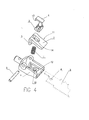
- Figure 4 shows an exploded perspective view of the embodiment of the present invention; and
- Figure 5 shows a perspective view of the assembled embodiment of the present invention.
-
- Figures 1, 2 and 3 show a sectional view of an embodiment of the blade clamp mechanism of the present invention during and after insertion of a
saw blade 9 in clamping and non-clamping positions. The blade clamp mechanism includes ahollow base 4 with an upper supporting surface (edge) 12 for supporting the underside of thesaw blade 9. Aclamping lever 11 is pivotally mounted on ahorizontal pivot 5 of thebase 4 and includes on a first side of the pivot 5 aclamp plate 7 capable of bearing against the upperside of thesaw blade 9 and on a second side of the pivot 5 aplate 3 downwardly dependent into thehollow base 4 at approximately 90° to theclamp plate 7. An inward face of the free end of plate 3 (ie the end remote from the pivot 5) is beveled. - A sliding
block 6 slidably mounted on thebase 4 has (at its lower end) alocking bevel 2 and at its upper end an invertedU-shaped plunger 13 capable of engaging the upper end ofplate 3. The slidingblock 6 extends through a throughhole 14 on theclamp plate 7. By means of aspring 1 mounted inside a cavity in the slidingblock 6 and on a protrusion (not shown) on thebase 4, the slidingblock 6 is biased upwardly (ie the blade clamp mechanism is biased towards the clamping position as described hereinafter). - In the clamping position (Figure 3) of the blade clamp mechanism, the
clamp plate 7 is clamped (see Figure 3) against thesaw blade 9 on the supportingsurface 12. In this position, the lockingbevel 2 engages the beveled face of the free end ofplate 3 and theplunger 13 is disengaged from the upper end ofplate 3. By virtue of the engagement of the lockingbevel 2 and the beveled face of the free end ofplate 3, thespring 1 gives the plate 3 a tendency to rotate (in the clockwise direction of Figure 3) and (by virtue of its linear restoring force) gives the plunger 13 a tendency to remain disengaged from the upper end ofplate 3. - To insert the
blade clamp 9, the slidingblock 6 is manually depressed against the restoring force of thespring 1. This causes the lockingbevel 2 to move downwardly to allow theplunger 13 to engage and press the upper end ofplate 3 causing theplate 3 to rotate (in the anti-clockwise direction of Figures 1 and 2) onpivot 5. This increases the gap between theclamp plate 7 and the supportingsurface 12 so that thesaw blade 9 may be easily inserted. Apositioning protrusion 10 on the supportingsurface 12 protrudes towards theclamp plate 7. After thesaw blade 9 is inserted between the supportingsurface 12 and theclamp plate 7, thepositioning protrusion 10 is seated in apositioning hole 8 in the saw blade 9 (see Figure 2). - To withdraw the
blade clamp 9, the slidingblock 6 is manually depressed against the restoring force of thespring 1. This causes the lockingbevel 2 to move downwardly to allow theplunger 13 to engage and press the upper end ofplate 3 causing theplate 3 to rotate (in the anti-clockwise direction of Figures 1 and 2) onpivot 5. This increases the gap between theclamp plate 7 and theblade clamp 9 so that thesaw blade 9 may be withdrawn.
Claims (18)
- A keyless blade clamp mechanism for clamping a blade [9] comprising:a base [4] with a supporting surface [12] for supporting the blade [9];a sliding block [6] slidably mounted on the base [4];an elastic member [1] mounted between the sliding block [6] and the base [4] for giving the sliding block [6] an upward tendency;a clamping lever [11] pivotally mounted on a horizontal pivot [5] on the base [4] which includes on a first side of the pivot [5] and opposed to the supporting surface [12] a clamp plate [7] capable of bearing against the upperside of the blade [9] and on a second side of the pivot [5] a downwardly dependent plate [3].
- A keyless blade clamp mechanism as claimed in claim 1 further comprising:wherein:a locking bevel [2] at a lower end of the sliding block [6] anda plunger [13] at an upper end of the sliding block [6]when the clamp plate [7] clamps the blade [9], the locking bevel [2] is engaged with an end of the plate [3] remote from the pivot [5] and the plunger [13] is disengaged from an end of the plate [3] at or near to the pivot [5] andwhen the clamp plate [7] is unclamped, the plunger [13] engages and presses the end of the plate [3] at or near to the pivot [5].
- A keyless blade clamp mechanism as claimed in claim 1 or 2, wherein the end of the plate [3] remote from the pivot [5] is beveled and when the clamp plate [7] clamps the saw blade [9], the locking bevel [2] is engaged with the beveled end of the plate [3] remote from the pivot [5].
- A keyless blade clamp mechanism as claimed in any preceding claim wherein said elastic member is a compressed spring [1].
- A keyless blade clamp mechanism as claimed in claim 1, wherein a compressed spring [1] is mounted between the sliding block [6] and the base [4] and biases the sliding block [6] upwardly giving the plunger [13] a tendency to disengage the plate [3].
- A keyless blade clamp mechanism as claimed in any preceding claim, wherein the sliding block [6] extends through a through hole [14] on the clamp plate [7].
- A keyless blade clamp mechanism as claimed in any preceding claim, wherein the plate [3] is downwardly dependent at approximately 90° to the clamp plate [7].
- A keyless blade clamp mechanism as claimed in any preceding claim further comprising:a positioning protrusion [10] on the supporting surface [12] or on the clamp plate [7] to cooperate with a positioning hole [8] provided in the blade [9].
- A blade clamp mechanism for clamping a blade [9] comprising:wherein the actuating member [6] is compressively mounted on the hollow base [4] such that a lower portion [2] of the actuating member [6] is urged into engagement with a lower portion of the plate [3] to pivotally bias the clamp plate [7] into the clamping position.a hollow base [4] with opposing sides defining an upper supporting edge [12] for supporting the blade [9];a pivot [5] mounted prominently on the supporting edge [12];a clamping lever [11] pivotally mounted on the pivot [5] which includes on a first side of the pivot [5] a clamp plate [7] capable of bearing against the upperside of the blade [9] supported on the supporting edge [12] and on a second side of the pivot [5] a plate [3] downwardly dependent into the hollow base [4]; andan actuating member [6] passing through the clamp plate [7] for actuating the clamp plate [7] between a clamping position in which the clamp plate [7] is clamped against the blade [9] supported on the supporting edge [12] and a non-clamping position in which the clamp plate [7] is not clamped against the blade [9] supported on the supporting edge [12],an elastic member [1] mounted between the actuating member [6] and the base [4] for giving the actuating member [6] an upward tendency,
- A blade clamp mechanism as claimed in claim 9 wherein the elastic member is a compression spring and the actuating member [6] is compressively mounted by the compression spring [1] between the actuating member [6] and the hollow base [4] to bias the blade clamp mechanism towards the clamping position.
- A blade clamp mechanism as claimed in claim 9 or 10 wherein the actuating member [6] is slidably mounted on the hollow base [4].
- A blade clamp mechanism as claimed in claim 9, 10 or 11 wherein the lower portion [2] of the actuating member [6] has a beveled face.
- A blade clamp mechanism as claimed in any of claims 9 to 12 wherein the lower portion of the plate [3] has a beveled face.
- A blade clamp mechanism as claimed in any of claims 9 to 13 wherein the actuating member [6] comprises:an exteriorly manipulable plunger [13] extending upwardly and rearwardly from a hollow lower body, wherein the hollow lower body is compressively mounted on the hollow base [4] such that in the clamping position the plunger [13] is linearly biased into disengagement from the upper end of the plate [3].
- A blade clamp mechanism as claimed in claim 14 wherein the exteriorly manipulable plunger [13] is linearly manipulable into engagement with the upper end of the plate [3] to pivot the clamp plate [7] into the non-clamping position.
- A blade clamp mechanism as claimed in claim 14 wherein a compression spring [1] is connected internally to the hollow lower body.
- A blade clamp mechanism as claimed in claim 9 wherein the lower portion of the plate [3] has a beveled face and the lower portion [2] of the actuating member [6] has a beveled face whereby the beveled face [2] of the actuating member [6] is urged into engagement with the beveled face of the plate [3] to pivotally bias clamp plate [7] into the clamping position.
- A cutting assembly comprising a keyless blade clamp mechanism as defined in any preceding claim and a blade.
Applications Claiming Priority (2)
| Application Number | Priority Date | Filing Date | Title |
|---|---|---|---|
| CN03112686.3A CN1278809C (en) | 2003-01-13 | 2003-01-13 | Quickly changeng and clamping mechanism of saw blade |
| CN03112686 | 2003-01-13 |
Publications (2)
| Publication Number | Publication Date |
|---|---|
| EP1437189A1 true EP1437189A1 (en) | 2004-07-14 |
| EP1437189B1 EP1437189B1 (en) | 2006-06-21 |
Family
ID=32477230
Family Applications (1)
| Application Number | Title | Priority Date | Filing Date |
|---|---|---|---|
| EP04250021A Expired - Lifetime EP1437189B1 (en) | 2003-01-13 | 2004-01-05 | Blade clamp mechanism |
Country Status (5)
| Country | Link |
|---|---|
| US (1) | US6854187B2 (en) |
| EP (1) | EP1437189B1 (en) |
| CN (1) | CN1278809C (en) |
| CA (1) | CA2455060C (en) |
| DE (1) | DE602004001233T2 (en) |
Cited By (5)
| Publication number | Priority date | Publication date | Assignee | Title |
|---|---|---|---|---|
| EP1527838A1 (en) * | 2003-10-28 | 2005-05-04 | BLACK & DECKER INC. | Blade clamp for reciprocating saw |
| GB2425984A (en) * | 2005-05-12 | 2006-11-15 | Mobiletron Electronics Co Ltd | A saw blade clamping mechanism |
| EP2524758A1 (en) * | 2011-05-18 | 2012-11-21 | Black & Decker Inc. | Power saw tool with blade clamp assembly |
| US9899899B2 (en) | 2013-10-25 | 2018-02-20 | Black & Decker Inc. | Handheld power tool with compact AC switch |
| GB2619364B (en) * | 2022-09-09 | 2024-05-29 | Apache Ltd | A handle for a saw and a saw comprising the same |
Families Citing this family (28)
| Publication number | Priority date | Publication date | Assignee | Title |
|---|---|---|---|---|
| US7022128B2 (en) | 2003-04-22 | 2006-04-04 | Becton, Dickinson And Company | Surgical knife safety handle |
| TW200509851A (en) * | 2003-04-22 | 2005-03-16 | Becton Dickinson Co | Surgical knife safety handle |
| US7055248B2 (en) * | 2004-04-30 | 2006-06-06 | Becton, Dickinson And Company | Surgical knife blade attachment and method for using same |
| TWM268151U (en) * | 2004-08-17 | 2005-06-21 | Guo-Rung Liu | Quick connecting and propping set for reciprocal type pneumatic tool |
| TWI369970B (en) | 2004-10-20 | 2012-08-11 | Beaver Visitec Int Us Inc | Surgical knife safety handle having user operable lock |
| US7325314B1 (en) * | 2005-03-15 | 2008-02-05 | King Jaws Metal Co., Ltd. | Handsaw having replaceable blade |
| DE102005049411B3 (en) * | 2005-10-13 | 2007-03-01 | Martor Kg | Knife, has operation lug, held outside of blade bolt at base plate, where inner surfaces hold bolt in its closed position close to plate and release bolt for opening bolt and taking out knife blade |
| CN1788900B (en) * | 2005-12-13 | 2010-04-28 | 苏州宝时得电动工具有限公司 | Saw bit clamping device |
| DE102006025768A1 (en) * | 2006-05-31 | 2007-12-13 | Robert Bosch Gmbh | Lifting saw with a fastening device for a saw blade |
| US7946041B2 (en) * | 2007-08-22 | 2011-05-24 | Joseph Frankl | T-back hand saw |
| US8813372B2 (en) | 2007-09-14 | 2014-08-26 | Milwaukee Electric Tool Corporation | Blade clamp mechanism |
| US8464430B2 (en) | 2008-02-07 | 2013-06-18 | Beaver-Visitec International (Us), Inc. | Retractable safety knife |
| US8230607B2 (en) | 2008-05-09 | 2012-07-31 | Milwaukee Electric Tool Corporation | Keyless blade clamp for a power tool |
| EP2123383B1 (en) * | 2008-05-20 | 2011-02-16 | Robert Bosch GmbH | Electrical device having a tool retention assembly |
| US8312632B2 (en) * | 2008-08-05 | 2012-11-20 | Stanley Black & Decker, Inc. | Saw blade handle with replaceable blades |
| US8356415B2 (en) * | 2009-12-18 | 2013-01-22 | Wen-Chen Lin | Scraping tool with blade lock assembly |
| US9642302B2 (en) * | 2010-06-01 | 2017-05-09 | Orlando Jerez | Rotary trimmer apparatus and related rotary head assembly |
| US8978257B2 (en) * | 2010-09-01 | 2015-03-17 | Elwood Dean Quimby | Utility knife with a blade having multiple cutting portions |
| US9156097B2 (en) * | 2012-03-20 | 2015-10-13 | Milwaukee Electric Tool Corporation | Reciprocating saw blade clamp |
| JP5921385B2 (en) * | 2012-08-22 | 2016-05-24 | 株式会社マキタ | Reciprocating saw |
| US9586329B2 (en) | 2013-06-13 | 2017-03-07 | Fiskars Brands, Inc. | Skinning knife with removable blade |
| CN103394755B (en) * | 2013-08-02 | 2015-10-14 | 铁鎯电动工具有限公司 | Saw blade clamping device and reciprocating saw thereof |
| WO2015195615A1 (en) * | 2014-06-16 | 2015-12-23 | Robert Bosch Gmbh | Blade and blade attachment system for an oscillating tool |
| US10350646B1 (en) | 2016-03-11 | 2019-07-16 | Kraig Darrell Nichols, Jr. | Automated surface scraping apparatus |
| CN108411551A (en) * | 2018-03-27 | 2018-08-17 | 苏州市远凌纺织有限公司 | A kind of non-woven fabrics flattening mechanism holding frame |
| CN108581073B (en) * | 2018-07-19 | 2024-03-08 | 珠海格力智能装备有限公司 | Clamping mechanism and pipe bending equipment with same |
| TW202243940A (en) * | 2021-05-14 | 2022-11-16 | 王坤旺 | Tool holder |
| CN116538414B (en) * | 2023-05-18 | 2026-02-10 | 深圳市纽尔科技有限公司 | A quick-release and easy-to-use fixing device |
Citations (5)
| Publication number | Priority date | Publication date | Assignee | Title |
|---|---|---|---|---|
| EP0582326A1 (en) * | 1992-07-29 | 1994-02-09 | Skil Europe B.V. | Saw-blade fixation device |
| DE4313718A1 (en) * | 1993-04-27 | 1994-11-03 | Bernd Hoeschele | Device for holding a saw blade |
| US6112420A (en) * | 1999-08-10 | 2000-09-05 | S-B Power Tool Company | Blade clamp for reciprocating saw |
| DE20013789U1 (en) * | 2000-08-10 | 2000-12-07 | Chen, Mei-Tung, Taipeh/T'ai-pei | Quick clamping device for the saw blade of an electric saber saw |
| JP2002011703A (en) * | 2000-06-28 | 2002-01-15 | Makita Corp | Apparatus for fitting blade of reciprocative cutting tool |
Family Cites Families (7)
| Publication number | Priority date | Publication date | Assignee | Title |
|---|---|---|---|---|
| US4106181A (en) * | 1976-08-09 | 1978-08-15 | American Safety Equipment Corporation | Quick release mechanism for oscillating saw blade |
| US6295736B1 (en) * | 1995-06-09 | 2001-10-02 | Black & Decker Inc. | Blade ejection mechanism for a saw blade clamping arrangement of a power tool |
| GB9604463D0 (en) * | 1996-03-01 | 1996-05-01 | Black & Decker Inc | A saw blade clamp |
| GB2322593B (en) * | 1997-02-28 | 1999-05-05 | Bosch Gmbh Robert | Clamping mechanism for a power tool |
| US5987758A (en) * | 1997-10-28 | 1999-11-23 | Ryobi North America, Inc. | Quick-change blade clamp |
| US6467177B2 (en) * | 1998-07-02 | 2002-10-22 | Black & Decker Inc. | Reciprocating saw blade clamp |
| US6209208B1 (en) | 1998-10-09 | 2001-04-03 | Milwaukee Electric Tool Corporarion | Keyless blade clamp mechanism |
-
2003
- 2003-01-13 CN CN03112686.3A patent/CN1278809C/en not_active Expired - Fee Related
-
2004
- 2004-01-05 EP EP04250021A patent/EP1437189B1/en not_active Expired - Lifetime
- 2004-01-05 DE DE602004001233T patent/DE602004001233T2/en not_active Expired - Fee Related
- 2004-01-12 CA CA002455060A patent/CA2455060C/en not_active Expired - Fee Related
- 2004-01-12 US US10/756,226 patent/US6854187B2/en not_active Expired - Fee Related
Patent Citations (5)
| Publication number | Priority date | Publication date | Assignee | Title |
|---|---|---|---|---|
| EP0582326A1 (en) * | 1992-07-29 | 1994-02-09 | Skil Europe B.V. | Saw-blade fixation device |
| DE4313718A1 (en) * | 1993-04-27 | 1994-11-03 | Bernd Hoeschele | Device for holding a saw blade |
| US6112420A (en) * | 1999-08-10 | 2000-09-05 | S-B Power Tool Company | Blade clamp for reciprocating saw |
| JP2002011703A (en) * | 2000-06-28 | 2002-01-15 | Makita Corp | Apparatus for fitting blade of reciprocative cutting tool |
| DE20013789U1 (en) * | 2000-08-10 | 2000-12-07 | Chen, Mei-Tung, Taipeh/T'ai-pei | Quick clamping device for the saw blade of an electric saber saw |
Non-Patent Citations (1)
| Title |
|---|
| PATENT ABSTRACTS OF JAPAN vol. 2002, no. 05 3 May 2002 (2002-05-03) * |
Cited By (8)
| Publication number | Priority date | Publication date | Assignee | Title |
|---|---|---|---|---|
| EP1527838A1 (en) * | 2003-10-28 | 2005-05-04 | BLACK & DECKER INC. | Blade clamp for reciprocating saw |
| GB2425984A (en) * | 2005-05-12 | 2006-11-15 | Mobiletron Electronics Co Ltd | A saw blade clamping mechanism |
| US7210232B2 (en) | 2005-05-12 | 2007-05-01 | Mobiletron Electronics Co., Ltd. | Saw blade clamping mechanism for a power tool |
| GB2425984B (en) * | 2005-05-12 | 2007-05-16 | Mobiletron Electronics Co Ltd | Saw blade clamping mechanism for a power sawing tool |
| EP2524758A1 (en) * | 2011-05-18 | 2012-11-21 | Black & Decker Inc. | Power saw tool with blade clamp assembly |
| US9321112B2 (en) | 2011-05-18 | 2016-04-26 | Black & Decker Inc. | Power saw tool |
| US9899899B2 (en) | 2013-10-25 | 2018-02-20 | Black & Decker Inc. | Handheld power tool with compact AC switch |
| GB2619364B (en) * | 2022-09-09 | 2024-05-29 | Apache Ltd | A handle for a saw and a saw comprising the same |
Also Published As
| Publication number | Publication date |
|---|---|
| DE602004001233T2 (en) | 2007-05-03 |
| CA2455060C (en) | 2006-09-12 |
| DE602004001233D1 (en) | 2006-08-03 |
| EP1437189B1 (en) | 2006-06-21 |
| CN1517166A (en) | 2004-08-04 |
| CA2455060A1 (en) | 2004-07-13 |
| CN1278809C (en) | 2006-10-11 |
| US20040226177A1 (en) | 2004-11-18 |
| US6854187B2 (en) | 2005-02-15 |
Similar Documents
| Publication | Publication Date | Title |
|---|---|---|
| EP1437189B1 (en) | Blade clamp mechanism | |
| US6283348B1 (en) | Cellular telephone clip | |
| CN101868376B (en) | Extendable roof rack | |
| US7222648B2 (en) | Bracket assembly for mobile stand | |
| US7052035B2 (en) | Assembly unit having an airbag module and a vehicle steering wheel | |
| JPH05335056A (en) | Connector for fixing body | |
| JP7386523B2 (en) | connector lock mechanism | |
| US7069765B2 (en) | Release mechanism for end forming machine | |
| EP3763480A1 (en) | Oscillating tool | |
| US20050039339A1 (en) | Saw blade camping device | |
| CN100531985C (en) | Reciprocating saw and slide stand locking mechanism | |
| US6938542B1 (en) | Embossing tool | |
| EP0944122A1 (en) | Removal/attachment device for use with compact electronic device | |
| US6312014B1 (en) | Shoulder anchor position adjusting device | |
| AU2006201868A1 (en) | Saw blade clamping mechanism for a power tool | |
| US20190105797A1 (en) | Distance adjustment mechanism for fence assembly of table saw | |
| US20070044323A1 (en) | Cutter having detachable cutter blade | |
| US20090007712A1 (en) | Shifter with one-touch locking knob | |
| EP2412578B1 (en) | Device for detachably attaching a holder for an electronic device | |
| WO2006133378B1 (en) | Quick change holder for cutting tool | |
| CN117212635B (en) | Connectors and disassembly/reassembly components | |
| CN110370367A (en) | A kind of dual-purpose cutting tool | |
| WO2005013423A3 (en) | Electrical plug-in connection part | |
| JPH05214869A (en) | Locking device for drawer | |
| JP4144031B2 (en) | Switching power supply |
Legal Events
| Date | Code | Title | Description |
|---|---|---|---|
| PUAI | Public reference made under article 153(3) epc to a published international application that has entered the european phase |
Free format text: ORIGINAL CODE: 0009012 |
|
| AK | Designated contracting states |
Kind code of ref document: A1 Designated state(s): AT BE BG CH CY CZ DE DK EE ES FI FR GB GR HU IE IT LI LU MC NL PT RO SE SI SK TR |
|
| AX | Request for extension of the european patent |
Extension state: AL LT LV MK |
|
| 17P | Request for examination filed |
Effective date: 20040920 |
|
| 17Q | First examination report despatched |
Effective date: 20050120 |
|
| AKX | Designation fees paid |
Designated state(s): DE FR GB |
|
| GRAP | Despatch of communication of intention to grant a patent |
Free format text: ORIGINAL CODE: EPIDOSNIGR1 |
|
| GRAS | Grant fee paid |
Free format text: ORIGINAL CODE: EPIDOSNIGR3 |
|
| GRAA | (expected) grant |
Free format text: ORIGINAL CODE: 0009210 |
|
| AK | Designated contracting states |
Kind code of ref document: B1 Designated state(s): DE FR GB |
|
| REG | Reference to a national code |
Ref country code: GB Ref legal event code: FG4D |
|
| REF | Corresponds to: |
Ref document number: 602004001233 Country of ref document: DE Date of ref document: 20060803 Kind code of ref document: P |
|
| PGFP | Annual fee paid to national office [announced via postgrant information from national office to epo] |
Ref country code: FR Payment date: 20061211 Year of fee payment: 4 |
|
| PGFP | Annual fee paid to national office [announced via postgrant information from national office to epo] |
Ref country code: DE Payment date: 20061214 Year of fee payment: 4 |
|
| ET | Fr: translation filed | ||
| PLBE | No opposition filed within time limit |
Free format text: ORIGINAL CODE: 0009261 |
|
| STAA | Information on the status of an ep patent application or granted ep patent |
Free format text: STATUS: NO OPPOSITION FILED WITHIN TIME LIMIT |
|
| 26N | No opposition filed |
Effective date: 20070322 |
|
| GBPC | Gb: european patent ceased through non-payment of renewal fee |
Effective date: 20080105 |
|
| PG25 | Lapsed in a contracting state [announced via postgrant information from national office to epo] |
Ref country code: DE Free format text: LAPSE BECAUSE OF NON-PAYMENT OF DUE FEES Effective date: 20080801 |
|
| REG | Reference to a national code |
Ref country code: FR Ref legal event code: ST Effective date: 20081029 |
|
| PG25 | Lapsed in a contracting state [announced via postgrant information from national office to epo] |
Ref country code: GB Free format text: LAPSE BECAUSE OF NON-PAYMENT OF DUE FEES Effective date: 20080105 |
|
| PG25 | Lapsed in a contracting state [announced via postgrant information from national office to epo] |
Ref country code: FR Free format text: LAPSE BECAUSE OF NON-PAYMENT OF DUE FEES Effective date: 20080131 |