EP1437163A1 - Verfahren und Vorrichtung zur Informationsübertragung zwischen Gleis und Fahrzeug einer Modelleisenbahn - Google Patents
Verfahren und Vorrichtung zur Informationsübertragung zwischen Gleis und Fahrzeug einer Modelleisenbahn Download PDFInfo
- Publication number
- EP1437163A1 EP1437163A1 EP03001856A EP03001856A EP1437163A1 EP 1437163 A1 EP1437163 A1 EP 1437163A1 EP 03001856 A EP03001856 A EP 03001856A EP 03001856 A EP03001856 A EP 03001856A EP 1437163 A1 EP1437163 A1 EP 1437163A1
- Authority
- EP
- European Patent Office
- Prior art keywords
- rail
- vehicle
- track
- voltage
- wheel
- Prior art date
- Legal status (The legal status is an assumption and is not a legal conclusion. Google has not performed a legal analysis and makes no representation as to the accuracy of the status listed.)
- Granted
Links
- 238000000034 method Methods 0.000 title claims description 10
- 230000005540 biological transmission Effects 0.000 claims abstract description 16
- 239000003990 capacitor Substances 0.000 claims description 41
- 230000008901 benefit Effects 0.000 claims description 4
- 238000012545 processing Methods 0.000 claims description 3
- 239000003989 dielectric material Substances 0.000 claims description 2
- 238000009434 installation Methods 0.000 claims 2
- 230000003137 locomotive effect Effects 0.000 abstract description 8
- 238000000926 separation method Methods 0.000 abstract description 2
- 238000005096 rolling process Methods 0.000 abstract 2
- 238000004146 energy storage Methods 0.000 description 11
- 230000008878 coupling Effects 0.000 description 6
- 238000010168 coupling process Methods 0.000 description 6
- 238000005859 coupling reaction Methods 0.000 description 6
- 238000001514 detection method Methods 0.000 description 4
- 238000010586 diagram Methods 0.000 description 4
- 238000012546 transfer Methods 0.000 description 4
- 230000008859 change Effects 0.000 description 2
- 230000001419 dependent effect Effects 0.000 description 2
- 238000013461 design Methods 0.000 description 2
- 238000011161 development Methods 0.000 description 2
- 230000018109 developmental process Effects 0.000 description 2
- 238000003079 width control Methods 0.000 description 2
- 238000007792 addition Methods 0.000 description 1
- 238000013459 approach Methods 0.000 description 1
- 230000003750 conditioning effect Effects 0.000 description 1
- 230000005611 electricity Effects 0.000 description 1
- 239000000446 fuel Substances 0.000 description 1
- 238000005259 measurement Methods 0.000 description 1
- 230000008569 process Effects 0.000 description 1
- 230000008929 regeneration Effects 0.000 description 1
- 238000011069 regeneration method Methods 0.000 description 1
- 230000002787 reinforcement Effects 0.000 description 1
- 230000035945 sensitivity Effects 0.000 description 1
- 230000002123 temporal effect Effects 0.000 description 1
Images


Classifications
-
- A—HUMAN NECESSITIES
- A63—SPORTS; GAMES; AMUSEMENTS
- A63H—TOYS, e.g. TOPS, DOLLS, HOOPS OR BUILDING BLOCKS
- A63H29/00—Drive mechanisms for toys in general
- A63H29/22—Electric drives
-
- A—HUMAN NECESSITIES
- A63—SPORTS; GAMES; AMUSEMENTS
- A63H—TOYS, e.g. TOPS, DOLLS, HOOPS OR BUILDING BLOCKS
- A63H18/00—Highways or trackways for toys; Propulsion by special interaction between vehicle and track
-
- A—HUMAN NECESSITIES
- A63—SPORTS; GAMES; AMUSEMENTS
- A63H—TOYS, e.g. TOPS, DOLLS, HOOPS OR BUILDING BLOCKS
- A63H18/00—Highways or trackways for toys; Propulsion by special interaction between vehicle and track
- A63H18/12—Electric current supply to toy vehicles through the track
-
- A—HUMAN NECESSITIES
- A63—SPORTS; GAMES; AMUSEMENTS
- A63H—TOYS, e.g. TOPS, DOLLS, HOOPS OR BUILDING BLOCKS
- A63H19/00—Model railways
- A63H19/24—Electric toy railways; Systems therefor
Definitions
- the invention is based on the object, a reliable control even at Contact disturbances between vehicle and rail of a model railway ready to provide, which is also still inexpensive. This task is done by the solved independent claims. Preferred developments are in the subclaims Are defined.
- the invention provides a contactless information transfer between track and Vehicle of a model railway plant safe to apply without radio such is explained below.
- capacitors can be known no DC voltage, but AC voltage transfer.
- the invention does this and the stated capacitive Use of coupling between wheel and rail or vehicle and rail.
- the existing between wheel and rail capacitor supplemented by further capacitors between vehicle and rail if necessary but also be replaced.
- the other capacitors can not only In addition, but also be used as an alternative to information transmission.
- To form the other capacitors can additional contact areas be provided or existing contact pads be used.
- any measure can be used in the event of loss of contact increases the capacity between vehicle and rail. You can do this also used by the rail spaced surfaces on the vehicle or be enlarged.
- the dielectric constant of the capacitor between vehicle and rail or between said surfaces and the Rail are enlarged. This can be done by attaching dielectrics Vehicle surfaces done. It was the above between wheel and Rail capacity significantly increased. The increase is from the Model railway size and the respective measures depending.
- control systems include the pulse width controls in analog mode and, in particular, the digital controllers in which, as a rule, a square-wave voltage and / or frequency-modulated square-wave voltage is applied to the track.
- This equation describes the frequency dependent resistor R c of a capacitor.
- a resistance R c of approximately 160 kOhm results for an alternating voltage with a frequency of 1 MHz to be transmitted.
- a resistance of this magnitude can be used for the invention with little technical effort. This is the case, for example, when the voltage on the track is a DC voltage or low-frequency AC voltage in the order of the mains frequency (50 to 60 Hz).
- Such a voltage can easily be superimposed on a high-frequency signal with the usual methods available to the person skilled in the art, with a frequency which is preferably in the MHz range.
- a Locomotive decoder or comparable decoder module or control module As is known, always has a small energy storage.
- the energy storage provides in case of a short power interruption the supply of the decoder circuit safe for about 20 to 30 ms, thus preventing unwanted Resetting the decoder when the contact is interrupted.
- This energy storage can also be advantageous for supplying the detection and treatment means for the said needle pulses or high-frequency superposition signals be used, so that this avoided a separate energy storage can be.
- contactless information or Data transmission is according to an advantageous embodiment of the invention
- a battery, a battery or a high-capacity capacitor as Energy storage connected to the engine control inside the vehicle, in addition to the continuous control also a continuous energy supply for the drive motor to ensure.
- the invention and its advantageous developments try to keep the cost of detecting the transmitted over the wheel-rail capacitor AC voltage low in the event of a loss of contact between the wheel and rail.
- the conventional digital controls with rectangular track signal in the kHz range this is readily possible according to the above statements.
- the superimposed alternating voltage for a cost-effective implementation of the invention should be rectangular at frequencies in the kHz range. In the MHz range, a sinusoidal voltage can be used with little technical effort.
- a superimposed square-wave voltage one can, for example, carry out a pulse width modulation to obtain different control signals.
- the high-frequency sinusoidal voltage is transmitted via the wheel-rail capacitor as such. It can thus be detected directly and need not be regenerated to ensure the control signal even at loss of contact. This is also the case in the case of frequencies which may even be below the audio frequency range in the case of the above capacity-increasing measures.
- the coupling of a superimposed AC voltage can be done behind the DC voltage transformer of the system, for example with the aid of a throttle and a capacitor. In the locomotive one can recover the alternating voltage by means of this circuit means.
- Figure 1 shows the structure in a locomotive, if according to the invention of a Digital control is assumed. Already present is the track 11,12 with the rectangular voltage 10 of a few kHz. About the wheels with pantographs 13,14 reaches the voltage to a decoder 20, where after appropriate Interpretation of the transmitted information a motor 21 in the direction and Speed can be controlled. New additions are coupling capacitors 15,16, whose task is only in a potential separation, and two Amplifier 17,18 whose outputs to the inputs of an RS flip-flop 19th are connected. The RS flip-flop 19 is connected to a data input of the decoder 20 connected. When there is a break in contact between the wheels and the track dashed line wheel-rail capacitors, as explained above.
- the coupling capacitors should 15, 16 be about ten times larger than the case of application and the type the interruption dependent wheel-rail capacitors. For the rest, can if necessary, when using amplifiers, the full track voltage cope with, waive the coupling capacitors.
- the power supply of the Amplifier 17,18 and the flip-flop 19 on the above-mentioned, not shown Energy source of the locomotive decoder 20 can also be another be provided additional small power supply or alternatively an additional Power source can be exploited for the traction motor.
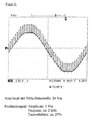
- FIG. 2 is an original recording of all relevant signals from FIG an oscilloscope.
- Channel R1 shows the track voltage as it appears at point 11, The amplitude is about 40 Vss.
- Channel R2 shows the voltage in case of a Interrupt at the input of the amplifier 17.
- the sensitivity of the oscilloscope here is only 100mV / cm.
- Channel R3 shows that amplified to 5 volts Signal now processed by the connected logic circuits can be.
- Channels 1,2,3 show the same situation only from the other Track side, so out of phase by 180 °. In this way arises on Output of the flip-flop 19 again identical in terms of timing Track signal (see channel (4)), which can be further processed by the decoder 20.
- capacitors or capacities between 11.12 and 13.14 allows the flanks of the Rectangular voltage in the form of needle pulses in the absence of electrical wheel-rail contact to detect and from the detected needle pulses the square wave voltage to regenerate and the information or data contained therein recycle.
- the circuit shown is simple, inexpensive and reliable and has the Advantage that they even with existing wheel-rail contact then properly can handle transmitted square wave voltage.
- the in in Figure 1 left links to the locomotive decoder 20 only to the power supply whereas all the data information is present and non-existent wheel-rail contact via the right connection to Locomotive decoder 20 takes place.
- the detection of the pulses and regeneration of the track voltage from this can done with a variety of logic circuits. In general, the Professional prefer the most cost-effective for him interpretation. The interpretation The regenerated track voltage is in a known manner in the locomotive decoder 20th
- FIG. 3 shows how an additional energy store 33 is connected can.
- a diode 32 decouples the power supply of the decoder 31 (usually a bridge rectifier) from the energy storage 33. Only when the out of the Track voltage 30 won internal supply voltage below the value of Energy storage 33 falls, the diode 32 is conductive and the decoder 31 is of outside, i. powered by the energy storage.
- energy storage can be used are: batteries, rechargeable batteries, high capacitive capacitors of example some farad capacity, fuel cells, etc. In the case of renewable energy sources like batteries or capacitors, these can be over appropriate known charging circuits are recharged as soon as the contact to Track is restored.
- Figure 4 shows an example of a detector for a DC or AC voltage superimposed high frequency.
- the track signal 41, 42 applied track signal 40 is again on additional capacitors 45,46 from the wheels 43,44 removed and placed on a high frequency amplifier 47 suitable.
- the Amplifier is selected to be in the case of a "normal" rail contact can be overridden and goes into the limit.
- two bandpasses 48,49 are provided, which are the respective frequency the superimposed high frequency in the case of a frequency modulation between two Frequency values, e.g. 1 MHz and 2 MHz, filter out. It is the rest in principle, only a single frequency value or more than two frequency values possible with a corresponding number of processing channels behind the Amplifier 47.
- the band passes are followed by two RF rectifiers 50, 51, whose output voltage is used to control a motor.
- the usual Power supply of the traction motor via the track voltage is in this figure not shown.
- Figure 5 shows an example of the track voltage 40 for processing in the Circuit of Figure 4.
- This is a DC voltage, the one higher-frequency sinusoidal AC voltage in the MHz range is superimposed.
- the DC voltage shown it may also be a low-frequency AC voltage of 50 Hz, 60 Hz or the like, whose Alternating voltage superposition of that shown in Figure 4 or else designed high-frequency detector is detected.
- FIG. 6 shows another form of possible superimposition in the form of a Pulse width modulated square wave in the kHz range on a Low-frequency 50 Hz sinewave signal as a track signal.
- the detector according to FIG. 1 or another needle pulse detector would come to Application, the pulse width modulated square wave voltage from the needle pulses regenerated.
- the pulse width modulation of the square-wave voltage can be dispensed with. Is a DC voltage provided as a track signal, so this can also be a square wave or pulse width modulated square wave voltage are superimposed.
- a Frequency modulation is also a Frequency modulation possible. This also applies to the square-wave voltage 10 of FIG. 1, which may be pulse width and / or frequency modulated.
- An energy storage device can be provided in all versions.
Landscapes
- Toys (AREA)
- Train Traffic Observation, Control, And Security (AREA)
- Electric Propulsion And Braking For Vehicles (AREA)
- Radar Systems Or Details Thereof (AREA)
Abstract
Description
Die Wechselspannungsübertragung mit einem Kondensator läßt sich durch zwei einfache Formeln beschreiben. Die erste lautet:
Die Erfindung und ihre vorteilhaften Weiterbildungen versuchen, im Falle eines Kontaktverlustes zwischen Rad und Schiene den Aufwand zur Detektion der über den Rad-Schiene-Kondensator übertragenen Wechselspannung gering zu halten. Bei den üblichen Digitalsteuerungen mit rechteckförmigem Gleissignal im kHz-Bereich ist dies gemäß den obigen Ausführungen ohne weiteres möglich. Wird bei einem konventionellen Analogbetrieb der Anlage eine Wechselspannung zur Übertragung eines Steuersignals überlagert, sollte die überlagerte Wechselspannung für eine kostengünstige Realisierung der Erfindung bei Frequenzen im kHz-Bereich rechteckförmig sein. Im MHz-Bereich kann mit geringem technischen Aufwand eine sinusförmige Spannung verwendet werden. Im Falle einer überlagerten Rechteckspannung kann man zur Gewinnung von unterschiedlichen Steuersignalen beispielsweise eine Pulsbreitenmodulation vornehmen. Im MHz-Bereich kann man bei sinusförmiger Wechselspannung z.B. durch Umschalten der Frequenzwerte von 1 MHz auf 2 MHz die Fahrtrichtung ändern. In diesem Fall wird die hochfrequente sinusförmige Spannung über den Rad-Schiene-Kondensator als solche übertragen. Sie kann somit direkt nachgewiesen werden und braucht nicht regeneriert zu werden, um das Steuersignal auch beim Kontaktverlust sicherzustellen. Dies ist auch bei Frequenzen, die sogar unter dem Tonfrequenzbereich liegen können, bei den obigen kapazitätssteigernden Maßnahmen der Fall. Die Einkopplung einer überlagerten Wechselspannung kann hinter dem Gleichspannungstransformator der Anlage beispielsweise mit Hilfe einer Drossel und eines Kondensators erfolgen. In der Lok kann man die Wechselspannung mittels dieser Schaltungsmittel wiedergewinnen.
Claims (11)
- Verfahren zur Übertragung von Information zwischen Gleis und einem auf dem Gleis befindlichen Fahrzeug einer Modelleisenbahnanlage,
dadurch gekennzeichnet, daß bei Verlust des elektrischen Kontaktes zwischen Fahrzeug und Schiene ein dann zwischen Fahrzeug und Schiene vorliegender Kondensator zur Informationsübertragung herangezogen wird, insbesondere ein dann zwischen Rad und Schiene vorliegender Kondensator. - Verfahren nach Anspruch 1,
dadurch gekennzeichnet, daß der zwischen Rad und Schiene vorliegende Kondensator durch zusätzliche Kondensatoren zwischen Fahrzeug und Schiene ergänzt wird, insbesondere durch Vorsehen zusätzlicher Kontaktabnahmeflächen oder unter Ausnutzung bereits vorhandener zusätzlicher Kontaktabnahmeflächen zwischen Fahrzeug und Schiene und/oder unter Ausnutzung von von der Schiene beabstandeten Flächen am Fahrzeug und/oder durch Vergrößern der Dielektrizitätskonstante des Kondensators zwischen Fahrzeug und Schiene. - Verfahren nach Anspruch 1 oder 2,
dadurch gekennzeichnet, daß bei einer Modelleisenbahnanlage mit einer Rechteckspannung als Informationsübertragungssignal an diesem Kondensator auftretende Nadelimpulse nachgewiesen und ausgewertet werden. - Verfahren nach Anspruch 3,
dadurch gekennzeichnet, daß die Rechteckspannung das Gleissignal einer digitalen Modelleisenbahnanlage ist, welches entsprechend einer Steuerinformation moduliert ist, wobei die Rechteckspannung aus den Nadelimpulsen regeneriert wird, oder eine Rechteckspannung ist, die einer am Gleis anliegenden Gleich- oder Wechselspannung überlagert ist, wobei aus den Nadelimpulsen eine zu übertragende Information regeneriert wird. - Verfahren nach Anspruch 1 oder 2,
dadurch gekennzeichnet, daß bei einer Modelleisenbahnanlage mit einer am Gleis anliegenden Gleichspannung oder niederfrequenten Wechselspannung der Gleisspannung ein höherfrequentes Informationsübertragungssignal überlagert wird, welches nach Übertragung über den Fahrzeug-Schiene bzw. Rad-Schiene-Kondensator erfaßt wird. - Vorrichtung zur Informationsübertragung zwischen Gleis und einem auf dem Gleis befindlichen Fahrzeug einer Modelleisenbahnanlage,
gekennzeichnet durch Mittel (15, 16, 17, 18, 19; 45, 46, 47, 48, 49, 50, 51 ) zum Nachweis und zum Aufbereiten von Signalen an einem zwischen Fahrzeug und und Schiene, insbesondere zwischen Rad und Schiene, vorliegenden Kondensator, der bei Verlust des elektrischen Kontaktes zwischen Fahrzeug und Schiene, insbesondere Rad und Schiene, auftritt und über den diese Signale in Folge des anliegenden Gleissignals übertragen werden. - Vorrichtung nach Anspruch 6,
dadurch gekennzeichnet, daß am Fahrzeug Mittel zur Schaffung zusätzlicher Kondensatoren zum Rad-Schiene-Kondensator zwischen Fahrzeug und Schiene vorgesehen sind, insbesondere zusätzliche Kontaktabnahmeflächen zwischen Fahrzeug und Schiene und/oder von der Schiene beabstandete Flächen am Fahrzeug und/oder am Fahrzeug angebrachte Dielektrika. - Vorrichtung nach Anspruch 6 oder 7,
dadurch gekennzeichnet, daß die übertragenen Signale Nadelimpulse sind, die aus einem rechteckförmigen Informationssignal herrühren, und die Mittel (15, 16, 17, 18, 19) eine Schaltung beinhalten, die die Nadelimpulse erfaßt und aus diesen eine zu übertragende Information regeneriert. - Vorrichtung nach Anspruch 6 oder 7,
dadurch gekennzeichnet, daß die Nadelimpulse aus einer am Gleis anliegenden Rechteckspannung herrühren, die entsprechend einer digitalen Steuerinformation moduliert ist, und die Mittel (15, 16, 17, 18, 19) eine Logikschaltung (19) aufweisen, die aus den verstärkten Nadelimpulsen die Steuerinformation regeneriert. - Vorrichtung nach Anspruch 6 oder 7,
dadurch gekennzeichnet, daß die von den Mitteln nachzuweisenden Signale als Wechselspannung vorliegen, die einer analogen Gleisspannung überlagert ist und über den zwischen Fahrzeug und Schiene vorliegenden Kondensator auch bei Verlust des elektrischen Kontaktes zwischen Fahrzeug und Schiene als solche übertragen wird. - Verfahren und/oder Vorrichtung nach einem der vorstehenden Ansprüche,
gekennzeichnet durch einen Energiespeicher (33) zur Bereitstellung einer Versorgungsspannung bei fehlendem Rad-Fahrzeug- bzw. Rad-Schiene-Kontakt.
Priority Applications (1)
| Application Number | Priority Date | Filing Date | Title |
|---|---|---|---|
| US10/749,445 US7198235B2 (en) | 2003-01-13 | 2003-12-31 | Method and apparatus for the transmission of information between track and vehicle of a model railroad |
Applications Claiming Priority (2)
| Application Number | Priority Date | Filing Date | Title |
|---|---|---|---|
| DE10301051 | 2003-01-13 | ||
| DE10301051A DE10301051A1 (de) | 2003-01-13 | 2003-01-13 | Verfahren und Vorrichtung zur Datenübertragung zwischen Gleis und Fahrzeug einer Modelleisenbahn |
Publications (3)
| Publication Number | Publication Date |
|---|---|
| EP1437163A1 true EP1437163A1 (de) | 2004-07-14 |
| EP1437163B1 EP1437163B1 (de) | 2006-05-24 |
| EP1437163B9 EP1437163B9 (de) | 2007-02-21 |
Family
ID=32478229
Family Applications (1)
| Application Number | Title | Priority Date | Filing Date |
|---|---|---|---|
| EP03001856A Expired - Lifetime EP1437163B9 (de) | 2003-01-13 | 2003-01-29 | Verfahren und Vorrichtung zur Informationsübertragung zwischen Gleis und Fahrzeug einer Modelleisenbahn |
Country Status (3)
| Country | Link |
|---|---|
| EP (1) | EP1437163B9 (de) |
| AT (1) | ATE327016T1 (de) |
| DE (2) | DE10301051A1 (de) |
Cited By (4)
| Publication number | Priority date | Publication date | Assignee | Title |
|---|---|---|---|---|
| AT516199A1 (de) * | 2014-09-10 | 2016-03-15 | Peter Dr Düll | Digital gesteuerte Modelleisenbahn |
| AT516655A1 (de) * | 2015-01-02 | 2016-07-15 | Peter Dr Düll | Digital gesteuerte Modelleisenbahn mit RailCom |
| AT517631A1 (de) * | 2015-08-31 | 2017-03-15 | Dr Düll Peter | Digital gesteuerte Modelleisenbahn mit TF-Übertragung des RailCom-Signales |
| CN116599600A (zh) * | 2023-04-26 | 2023-08-15 | 西安理工大学 | 钢轨中无信道衰落补偿的超声通信方法 |
Families Citing this family (1)
| Publication number | Priority date | Publication date | Assignee | Title |
|---|---|---|---|---|
| DE102016107970A1 (de) * | 2016-04-29 | 2017-11-02 | Endress + Hauser Gmbh + Co. Kg | Koppelelement für ein kapazitives Füllstandsmessgerät |
Citations (5)
| Publication number | Priority date | Publication date | Assignee | Title |
|---|---|---|---|---|
| US2990964A (en) * | 1957-11-04 | 1961-07-04 | Jan C Timmer | Toy electric train assembly |
| DE2261992A1 (de) * | 1972-12-19 | 1974-06-20 | Fleischmann Geb | Vorrichtung zur hochfrequenz-entstoerung gleitender oder rollender kontakte |
| DE2641841A1 (de) * | 1976-09-17 | 1978-07-20 | Jan Kralicek | Verfahren zur fernuebertragung mehrerer steuerfunktionen |
| DE2848354A1 (de) * | 1978-11-08 | 1980-05-22 | Helag Electronic Gmbh | Spannungsversorgung fuer eine modelleisenbahn o.dgl. |
| DE2931524A1 (de) * | 1979-08-03 | 1981-02-19 | Jens Freese | Einrichtung zur richtungs- und geschwindigkeitssteuerung einer dampfbetriebenen modell-lokomotive |
-
2003
- 2003-01-13 DE DE10301051A patent/DE10301051A1/de not_active Withdrawn
- 2003-01-29 EP EP03001856A patent/EP1437163B9/de not_active Expired - Lifetime
- 2003-01-29 DE DE50303460T patent/DE50303460D1/de not_active Expired - Lifetime
- 2003-01-29 AT AT03001856T patent/ATE327016T1/de active
Patent Citations (5)
| Publication number | Priority date | Publication date | Assignee | Title |
|---|---|---|---|---|
| US2990964A (en) * | 1957-11-04 | 1961-07-04 | Jan C Timmer | Toy electric train assembly |
| DE2261992A1 (de) * | 1972-12-19 | 1974-06-20 | Fleischmann Geb | Vorrichtung zur hochfrequenz-entstoerung gleitender oder rollender kontakte |
| DE2641841A1 (de) * | 1976-09-17 | 1978-07-20 | Jan Kralicek | Verfahren zur fernuebertragung mehrerer steuerfunktionen |
| DE2848354A1 (de) * | 1978-11-08 | 1980-05-22 | Helag Electronic Gmbh | Spannungsversorgung fuer eine modelleisenbahn o.dgl. |
| DE2931524A1 (de) * | 1979-08-03 | 1981-02-19 | Jens Freese | Einrichtung zur richtungs- und geschwindigkeitssteuerung einer dampfbetriebenen modell-lokomotive |
Cited By (6)
| Publication number | Priority date | Publication date | Assignee | Title |
|---|---|---|---|---|
| AT516199A1 (de) * | 2014-09-10 | 2016-03-15 | Peter Dr Düll | Digital gesteuerte Modelleisenbahn |
| AT516199B1 (de) * | 2014-09-10 | 2018-09-15 | Peter Dr Duell | Digital gesteuerte Modelleisenbahn |
| AT516655A1 (de) * | 2015-01-02 | 2016-07-15 | Peter Dr Düll | Digital gesteuerte Modelleisenbahn mit RailCom |
| AT517631A1 (de) * | 2015-08-31 | 2017-03-15 | Dr Düll Peter | Digital gesteuerte Modelleisenbahn mit TF-Übertragung des RailCom-Signales |
| AT517631B1 (de) * | 2015-08-31 | 2018-10-15 | Peter Dr Duell | Digital gesteuerte Modelleisenbahn mit TF-Übertragung des RailCom-Signales |
| CN116599600A (zh) * | 2023-04-26 | 2023-08-15 | 西安理工大学 | 钢轨中无信道衰落补偿的超声通信方法 |
Also Published As
| Publication number | Publication date |
|---|---|
| EP1437163B1 (de) | 2006-05-24 |
| EP1437163B9 (de) | 2007-02-21 |
| DE10301051A1 (de) | 2004-07-22 |
| DE50303460D1 (de) | 2006-06-29 |
| ATE327016T1 (de) | 2006-06-15 |
Similar Documents
| Publication | Publication Date | Title |
|---|---|---|
| DE19634714B4 (de) | Anordnung für ein Kraftfahrzeug-Regelungssystem | |
| DE102007040340B4 (de) | Verfahren zum Betreiben einer Radelektronik, Radelektronik und Reifenkontrollsystem | |
| DE102010045234A1 (de) | Energieversorgungs-Einrichtung, Vorrichtung und Anordnung mit einer solchen sowie Verfahren zur Energieversorgung zumindest eines Streckenelementes des spurgebundenen Verkehrs | |
| EP2868548B1 (de) | Verfahren zur Überwachung eines Schaltungszustandes eines Schalters eines Zugsicherungssystem, sowie Zugsicherungssystem | |
| DE69404218T2 (de) | Impedanzverbindung für Schienenwege | |
| EP2218624A2 (de) | Radsensor, Eisenbahnanlage mit zumindest einem Radsensor sowie Verfahren zum Betreiben einer Eisenbahnanlage | |
| WO2010102898A1 (de) | Verfahren zum betreiben einer zugbeeinflussungseinrichtung, streckenseitige elektronische einheit und balise für eine zugbeeinflussungseinrichtung sowie zugbeeinflussungseinrichtung | |
| EP2484019B1 (de) | Verfahren zur datenübertragung von einem sender zu einem empfänger in einem wechselspannungsnetz sowie vorrichtung zur datenübertragung für wechselspannungsnetze | |
| EP2000385A1 (de) | Vorrichtung zur Übertragung von Daten zwischen einer fest installierten Datenübertragungseinheit und einem beweglichen Objekt | |
| DE102020003222A1 (de) | Verfahren zur Überwachung einer Y-Kapazität eines elektrisch betriebenen Fahrzeugs, sowie elektronisches Überwachungssystem | |
| DE102016114322B4 (de) | Netzwerkvorrichtung sowie System mit einer Vielzahl von Netzwerkvorrichtungen | |
| EP1437163B1 (de) | Verfahren und Vorrichtung zur Informationsübertragung zwischen Gleis und Fahrzeug einer Modelleisenbahn | |
| DE19909244C2 (de) | Verfahren zum Übertragen von Daten über einen elektrischen Antriebsstrom für Fahrzeuge führenden Fahrstromleiter | |
| EP1240054B1 (de) | Schaltungsanordnung zur aktivierung eines can-bus-steuergerätes | |
| DE2903860C2 (de) | Einrichtung zur Gleichstromversorgung eines Verbrauchers und zur gleichzeitigen Informationsübertragung über ein Aderpaar | |
| DE2846801C2 (de) | Steuerungs-System für spurgeführte Modellfahrzeuge | |
| DE69816285T2 (de) | Polaritätsdetektor in einer durchgehenden leitung im zug und stromversorgung mit polaritätswechsel | |
| EP2380796B1 (de) | Gewährleistung einer niederohmigen elektrischen Verbindung zwischen Rädern eines Schienenfahrzeugs und Fahrschienen | |
| DE19631564B4 (de) | Verfahren zur Anbauüberwachung von Radsensoren für Bahnanlagen und Einrichtung zur Durchführung dieses Verfahrens | |
| DE3025035C2 (de) | Verfahren und Anordnung zum unabhängigen Betreiben mehrerer elektrischer Triebfahrzeuge einer Modell- und Spielzeugeisenbahnanlage | |
| EP4711186A1 (de) | Leistungsmodulationsbasiertes laden einer batterie eines schienenfahrzeugs | |
| DE19952980A1 (de) | Anordnung zur mehrkanaligen Signalübertragung zwischen bewegten Einheiten | |
| AT516199B1 (de) | Digital gesteuerte Modelleisenbahn | |
| DE3402349C2 (de) | ||
| DE102018210398B4 (de) | Empfangseinrichtung und Anordnung zur induktiven Energieübertragung sowie Verfahren zur Übertragung eines Fehlersignals |
Legal Events
| Date | Code | Title | Description |
|---|---|---|---|
| PUAI | Public reference made under article 153(3) epc to a published international application that has entered the european phase |
Free format text: ORIGINAL CODE: 0009012 |
|
| AK | Designated contracting states |
Kind code of ref document: A1 Designated state(s): AT BE BG CH CY CZ DE DK EE ES FI FR GB GR HU IE IT LI LU MC NL PT SE SI SK TR |
|
| AX | Request for extension of the european patent |
Extension state: AL LT LV MK RO |
|
| 17P | Request for examination filed |
Effective date: 20040811 |
|
| 17Q | First examination report despatched |
Effective date: 20040913 |
|
| AKX | Designation fees paid |
Designated state(s): AT BE BG CH CY CZ DE DK EE ES FI FR GB GR HU IE IT LI LU MC NL PT SE SI SK TR |
|
| GRAP | Despatch of communication of intention to grant a patent |
Free format text: ORIGINAL CODE: EPIDOSNIGR1 |
|
| GRAS | Grant fee paid |
Free format text: ORIGINAL CODE: EPIDOSNIGR3 |
|
| GRAA | (expected) grant |
Free format text: ORIGINAL CODE: 0009210 |
|
| AK | Designated contracting states |
Kind code of ref document: B1 Designated state(s): AT BE BG CH CY CZ DE DK EE ES FI FR GB GR HU IE IT LI LU MC NL PT SE SI SK TR |
|
| PG25 | Lapsed in a contracting state [announced via postgrant information from national office to epo] |
Ref country code: CZ Free format text: LAPSE BECAUSE OF FAILURE TO SUBMIT A TRANSLATION OF THE DESCRIPTION OR TO PAY THE FEE WITHIN THE PRESCRIBED TIME-LIMIT Effective date: 20060524 Ref country code: SI Free format text: LAPSE BECAUSE OF FAILURE TO SUBMIT A TRANSLATION OF THE DESCRIPTION OR TO PAY THE FEE WITHIN THE PRESCRIBED TIME-LIMIT Effective date: 20060524 Ref country code: IT Free format text: LAPSE BECAUSE OF FAILURE TO SUBMIT A TRANSLATION OF THE DESCRIPTION OR TO PAY THE FEE WITHIN THE PRESCRIBED TIME-LIMIT;WARNING: LAPSES OF ITALIAN PATENTS WITH EFFECTIVE DATE BEFORE 2007 MAY HAVE OCCURRED AT ANY TIME BEFORE 2007. THE CORRECT EFFECTIVE DATE MAY BE DIFFERENT FROM THE ONE RECORDED. Effective date: 20060524 Ref country code: NL Free format text: LAPSE BECAUSE OF FAILURE TO SUBMIT A TRANSLATION OF THE DESCRIPTION OR TO PAY THE FEE WITHIN THE PRESCRIBED TIME-LIMIT Effective date: 20060524 Ref country code: FI Free format text: LAPSE BECAUSE OF FAILURE TO SUBMIT A TRANSLATION OF THE DESCRIPTION OR TO PAY THE FEE WITHIN THE PRESCRIBED TIME-LIMIT Effective date: 20060524 Ref country code: IE Free format text: LAPSE BECAUSE OF FAILURE TO SUBMIT A TRANSLATION OF THE DESCRIPTION OR TO PAY THE FEE WITHIN THE PRESCRIBED TIME-LIMIT Effective date: 20060524 Ref country code: SK Free format text: LAPSE BECAUSE OF FAILURE TO SUBMIT A TRANSLATION OF THE DESCRIPTION OR TO PAY THE FEE WITHIN THE PRESCRIBED TIME-LIMIT Effective date: 20060524 |
|
| REG | Reference to a national code |
Ref country code: GB Ref legal event code: FG4D Free format text: NOT ENGLISH |
|
| REG | Reference to a national code |
Ref country code: CH Ref legal event code: EP |
|
| REG | Reference to a national code |
Ref country code: IE Ref legal event code: FG4D Free format text: LANGUAGE OF EP DOCUMENT: GERMAN |
|
| REF | Corresponds to: |
Ref document number: 50303460 Country of ref document: DE Date of ref document: 20060629 Kind code of ref document: P |
|
| PG25 | Lapsed in a contracting state [announced via postgrant information from national office to epo] |
Ref country code: SE Free format text: LAPSE BECAUSE OF FAILURE TO SUBMIT A TRANSLATION OF THE DESCRIPTION OR TO PAY THE FEE WITHIN THE PRESCRIBED TIME-LIMIT Effective date: 20060824 Ref country code: DK Free format text: LAPSE BECAUSE OF FAILURE TO SUBMIT A TRANSLATION OF THE DESCRIPTION OR TO PAY THE FEE WITHIN THE PRESCRIBED TIME-LIMIT Effective date: 20060824 |
|
| PG25 | Lapsed in a contracting state [announced via postgrant information from national office to epo] |
Ref country code: ES Free format text: LAPSE BECAUSE OF FAILURE TO SUBMIT A TRANSLATION OF THE DESCRIPTION OR TO PAY THE FEE WITHIN THE PRESCRIBED TIME-LIMIT Effective date: 20060904 |
|
| REG | Reference to a national code |
Ref country code: CH Ref legal event code: NV Representative=s name: E. BLUM & CO. PATENTANWAELTE |
|
| GBT | Gb: translation of ep patent filed (gb section 77(6)(a)/1977) |
Effective date: 20060911 |
|
| PG25 | Lapsed in a contracting state [announced via postgrant information from national office to epo] |
Ref country code: PT Free format text: LAPSE BECAUSE OF FAILURE TO SUBMIT A TRANSLATION OF THE DESCRIPTION OR TO PAY THE FEE WITHIN THE PRESCRIBED TIME-LIMIT Effective date: 20061024 |
|
| NLV1 | Nl: lapsed or annulled due to failure to fulfill the requirements of art. 29p and 29m of the patents act | ||
| ET | Fr: translation filed | ||
| REG | Reference to a national code |
Ref country code: IE Ref legal event code: FD4D |
|
| PG25 | Lapsed in a contracting state [announced via postgrant information from national office to epo] |
Ref country code: MC Free format text: LAPSE BECAUSE OF NON-PAYMENT OF DUE FEES Effective date: 20070131 |
|
| PLBE | No opposition filed within time limit |
Free format text: ORIGINAL CODE: 0009261 |
|
| STAA | Information on the status of an ep patent application or granted ep patent |
Free format text: STATUS: NO OPPOSITION FILED WITHIN TIME LIMIT |
|
| 26N | No opposition filed |
Effective date: 20070227 |
|
| REG | Reference to a national code |
Ref country code: CH Ref legal event code: PFA Owner name: LENZ ELEKTRONIK GMBH Free format text: LENZ ELEKTRONIK GMBH#HUETTENBERGSTRASSE 29#35398 GIESSEN (DE) -TRANSFER TO- LENZ ELEKTRONIK GMBH#HUETTENBERGSTRASSE 29#35398 GIESSEN (DE) |
|
| BERE | Be: lapsed |
Owner name: LENZ ELEKTRONIK G.M.B.H. Effective date: 20070131 |
|
| PG25 | Lapsed in a contracting state [announced via postgrant information from national office to epo] |
Ref country code: BE Free format text: LAPSE BECAUSE OF NON-PAYMENT OF DUE FEES Effective date: 20070131 |
|
| PG25 | Lapsed in a contracting state [announced via postgrant information from national office to epo] |
Ref country code: GR Free format text: LAPSE BECAUSE OF FAILURE TO SUBMIT A TRANSLATION OF THE DESCRIPTION OR TO PAY THE FEE WITHIN THE PRESCRIBED TIME-LIMIT Effective date: 20060825 |
|
| PGFP | Annual fee paid to national office [announced via postgrant information from national office to epo] |
Ref country code: FR Payment date: 20070118 Year of fee payment: 5 |
|
| PG25 | Lapsed in a contracting state [announced via postgrant information from national office to epo] |
Ref country code: BG Free format text: LAPSE BECAUSE OF FAILURE TO SUBMIT A TRANSLATION OF THE DESCRIPTION OR TO PAY THE FEE WITHIN THE PRESCRIBED TIME-LIMIT Effective date: 20060824 |
|
| PG25 | Lapsed in a contracting state [announced via postgrant information from national office to epo] |
Ref country code: EE Free format text: LAPSE BECAUSE OF FAILURE TO SUBMIT A TRANSLATION OF THE DESCRIPTION OR TO PAY THE FEE WITHIN THE PRESCRIBED TIME-LIMIT Effective date: 20060524 |
|
| REG | Reference to a national code |
Ref country code: FR Ref legal event code: ST Effective date: 20081029 |
|
| PG25 | Lapsed in a contracting state [announced via postgrant information from national office to epo] |
Ref country code: FR Free format text: LAPSE BECAUSE OF NON-PAYMENT OF DUE FEES Effective date: 20080131 |
|
| PG25 | Lapsed in a contracting state [announced via postgrant information from national office to epo] |
Ref country code: CY Free format text: LAPSE BECAUSE OF FAILURE TO SUBMIT A TRANSLATION OF THE DESCRIPTION OR TO PAY THE FEE WITHIN THE PRESCRIBED TIME-LIMIT Effective date: 20060524 Ref country code: LU Free format text: LAPSE BECAUSE OF NON-PAYMENT OF DUE FEES Effective date: 20070129 |
|
| PG25 | Lapsed in a contracting state [announced via postgrant information from national office to epo] |
Ref country code: TR Free format text: LAPSE BECAUSE OF FAILURE TO SUBMIT A TRANSLATION OF THE DESCRIPTION OR TO PAY THE FEE WITHIN THE PRESCRIBED TIME-LIMIT Effective date: 20060524 Ref country code: HU Free format text: LAPSE BECAUSE OF FAILURE TO SUBMIT A TRANSLATION OF THE DESCRIPTION OR TO PAY THE FEE WITHIN THE PRESCRIBED TIME-LIMIT Effective date: 20061125 |
|
| REG | Reference to a national code |
Ref country code: DE Ref legal event code: R082 Ref document number: 50303460 Country of ref document: DE Representative=s name: ADVOTEC. PATENT- UND RECHTSANWAELTE, DE |
|
| PGFP | Annual fee paid to national office [announced via postgrant information from national office to epo] |
Ref country code: CH Payment date: 20140124 Year of fee payment: 12 |
|
| REG | Reference to a national code |
Ref country code: CH Ref legal event code: PL |
|
| PG25 | Lapsed in a contracting state [announced via postgrant information from national office to epo] |
Ref country code: LI Free format text: LAPSE BECAUSE OF NON-PAYMENT OF DUE FEES Effective date: 20150131 Ref country code: CH Free format text: LAPSE BECAUSE OF NON-PAYMENT OF DUE FEES Effective date: 20150131 |
|
| PGFP | Annual fee paid to national office [announced via postgrant information from national office to epo] |
Ref country code: GB Payment date: 20170125 Year of fee payment: 15 Ref country code: AT Payment date: 20170120 Year of fee payment: 15 |
|
| PGFP | Annual fee paid to national office [announced via postgrant information from national office to epo] |
Ref country code: DE Payment date: 20180321 Year of fee payment: 16 |
|
| REG | Reference to a national code |
Ref country code: AT Ref legal event code: MM01 Ref document number: 327016 Country of ref document: AT Kind code of ref document: T Effective date: 20180129 |
|
| GBPC | Gb: european patent ceased through non-payment of renewal fee |
Effective date: 20180129 |
|
| PG25 | Lapsed in a contracting state [announced via postgrant information from national office to epo] |
Ref country code: GB Free format text: LAPSE BECAUSE OF NON-PAYMENT OF DUE FEES Effective date: 20180129 Ref country code: AT Free format text: LAPSE BECAUSE OF NON-PAYMENT OF DUE FEES Effective date: 20180129 |
|
| REG | Reference to a national code |
Ref country code: DE Ref legal event code: R119 Ref document number: 50303460 Country of ref document: DE |
|
| PG25 | Lapsed in a contracting state [announced via postgrant information from national office to epo] |
Ref country code: DE Free format text: LAPSE BECAUSE OF NON-PAYMENT OF DUE FEES Effective date: 20190801 |