EP1436136B1 - Method for extrusion coating multiple webs - Google Patents
Method for extrusion coating multiple webs Download PDFInfo
- Publication number
- EP1436136B1 EP1436136B1 EP02801725A EP02801725A EP1436136B1 EP 1436136 B1 EP1436136 B1 EP 1436136B1 EP 02801725 A EP02801725 A EP 02801725A EP 02801725 A EP02801725 A EP 02801725A EP 1436136 B1 EP1436136 B1 EP 1436136B1
- Authority
- EP
- European Patent Office
- Prior art keywords
- webs
- web
- coating
- polymer
- extrusion
- Prior art date
- Legal status (The legal status is an assumption and is not a legal conclusion. Google has not performed a legal analysis and makes no representation as to the accuracy of the status listed.)
- Expired - Lifetime
Links
Images



Classifications
-
- B—PERFORMING OPERATIONS; TRANSPORTING
- B32—LAYERED PRODUCTS
- B32B—LAYERED PRODUCTS, i.e. PRODUCTS BUILT-UP OF STRATA OF FLAT OR NON-FLAT, e.g. CELLULAR OR HONEYCOMB, FORM
- B32B37/00—Methods or apparatus for laminating, e.g. by curing or by ultrasonic bonding
- B32B37/14—Methods or apparatus for laminating, e.g. by curing or by ultrasonic bonding characterised by the properties of the layers
- B32B37/24—Methods or apparatus for laminating, e.g. by curing or by ultrasonic bonding characterised by the properties of the layers with at least one layer not being coherent before laminating, e.g. made up from granular material sprinkled onto a substrate
-
- B—PERFORMING OPERATIONS; TRANSPORTING
- B05—SPRAYING OR ATOMISING IN GENERAL; APPLYING FLUENT MATERIALS TO SURFACES, IN GENERAL
- B05D—PROCESSES FOR APPLYING FLUENT MATERIALS TO SURFACES, IN GENERAL
- B05D1/00—Processes for applying liquids or other fluent materials
- B05D1/26—Processes for applying liquids or other fluent materials performed by applying the liquid or other fluent material from an outlet device in contact with, or almost in contact with, the surface
- B05D1/265—Extrusion coatings
-
- B—PERFORMING OPERATIONS; TRANSPORTING
- B29—WORKING OF PLASTICS; WORKING OF SUBSTANCES IN A PLASTIC STATE IN GENERAL
- B29C—SHAPING OR JOINING OF PLASTICS; SHAPING OF MATERIAL IN A PLASTIC STATE, NOT OTHERWISE PROVIDED FOR; AFTER-TREATMENT OF THE SHAPED PRODUCTS, e.g. REPAIRING
- B29C48/00—Extrusion moulding, i.e. expressing the moulding material through a die or nozzle which imparts the desired form; Apparatus therefor
- B29C48/03—Extrusion moulding, i.e. expressing the moulding material through a die or nozzle which imparts the desired form; Apparatus therefor characterised by the shape of the extruded material at extrusion
- B29C48/07—Flat, e.g. panels
- B29C48/08—Flat, e.g. panels flexible, e.g. films
-
- B—PERFORMING OPERATIONS; TRANSPORTING
- B29—WORKING OF PLASTICS; WORKING OF SUBSTANCES IN A PLASTIC STATE IN GENERAL
- B29C—SHAPING OR JOINING OF PLASTICS; SHAPING OF MATERIAL IN A PLASTIC STATE, NOT OTHERWISE PROVIDED FOR; AFTER-TREATMENT OF THE SHAPED PRODUCTS, e.g. REPAIRING
- B29C48/00—Extrusion moulding, i.e. expressing the moulding material through a die or nozzle which imparts the desired form; Apparatus therefor
- B29C48/25—Component parts, details or accessories; Auxiliary operations
- B29C48/88—Thermal treatment of the stream of extruded material, e.g. cooling
- B29C48/911—Cooling
- B29C48/9135—Cooling of flat articles, e.g. using specially adapted supporting means
- B29C48/914—Cooling drums
-
- B—PERFORMING OPERATIONS; TRANSPORTING
- B32—LAYERED PRODUCTS
- B32B—LAYERED PRODUCTS, i.e. PRODUCTS BUILT-UP OF STRATA OF FLAT OR NON-FLAT, e.g. CELLULAR OR HONEYCOMB, FORM
- B32B27/00—Layered products comprising a layer of synthetic resin
- B32B27/06—Layered products comprising a layer of synthetic resin as the main or only constituent of a layer, which is next to another layer of the same or of a different material
- B32B27/10—Layered products comprising a layer of synthetic resin as the main or only constituent of a layer, which is next to another layer of the same or of a different material of paper or cardboard
-
- B—PERFORMING OPERATIONS; TRANSPORTING
- B05—SPRAYING OR ATOMISING IN GENERAL; APPLYING FLUENT MATERIALS TO SURFACES, IN GENERAL
- B05D—PROCESSES FOR APPLYING FLUENT MATERIALS TO SURFACES, IN GENERAL
- B05D2252/00—Sheets
- B05D2252/02—Sheets of indefinite length
-
- B—PERFORMING OPERATIONS; TRANSPORTING
- B29—WORKING OF PLASTICS; WORKING OF SUBSTANCES IN A PLASTIC STATE IN GENERAL
- B29C—SHAPING OR JOINING OF PLASTICS; SHAPING OF MATERIAL IN A PLASTIC STATE, NOT OTHERWISE PROVIDED FOR; AFTER-TREATMENT OF THE SHAPED PRODUCTS, e.g. REPAIRING
- B29C48/00—Extrusion moulding, i.e. expressing the moulding material through a die or nozzle which imparts the desired form; Apparatus therefor
- B29C48/25—Component parts, details or accessories; Auxiliary operations
- B29C48/30—Extrusion nozzles or dies
- B29C48/305—Extrusion nozzles or dies having a wide opening, e.g. for forming sheets
-
- B—PERFORMING OPERATIONS; TRANSPORTING
- B29—WORKING OF PLASTICS; WORKING OF SUBSTANCES IN A PLASTIC STATE IN GENERAL
- B29L—INDEXING SCHEME ASSOCIATED WITH SUBCLASS B29C, RELATING TO PARTICULAR ARTICLES
- B29L2009/00—Layered products
-
- B—PERFORMING OPERATIONS; TRANSPORTING
- B32—LAYERED PRODUCTS
- B32B—LAYERED PRODUCTS, i.e. PRODUCTS BUILT-UP OF STRATA OF FLAT OR NON-FLAT, e.g. CELLULAR OR HONEYCOMB, FORM
- B32B37/00—Methods or apparatus for laminating, e.g. by curing or by ultrasonic bonding
- B32B37/14—Methods or apparatus for laminating, e.g. by curing or by ultrasonic bonding characterised by the properties of the layers
- B32B37/24—Methods or apparatus for laminating, e.g. by curing or by ultrasonic bonding characterised by the properties of the layers with at least one layer not being coherent before laminating, e.g. made up from granular material sprinkled onto a substrate
- B32B2037/243—Coating
-
- B—PERFORMING OPERATIONS; TRANSPORTING
- B32—LAYERED PRODUCTS
- B32B—LAYERED PRODUCTS, i.e. PRODUCTS BUILT-UP OF STRATA OF FLAT OR NON-FLAT, e.g. CELLULAR OR HONEYCOMB, FORM
- B32B37/00—Methods or apparatus for laminating, e.g. by curing or by ultrasonic bonding
- B32B37/14—Methods or apparatus for laminating, e.g. by curing or by ultrasonic bonding characterised by the properties of the layers
- B32B37/16—Methods or apparatus for laminating, e.g. by curing or by ultrasonic bonding characterised by the properties of the layers with all layers existing as coherent layers before laminating
- B32B37/20—Methods or apparatus for laminating, e.g. by curing or by ultrasonic bonding characterised by the properties of the layers with all layers existing as coherent layers before laminating involving the assembly of continuous webs only
-
- B—PERFORMING OPERATIONS; TRANSPORTING
- B32—LAYERED PRODUCTS
- B32B—LAYERED PRODUCTS, i.e. PRODUCTS BUILT-UP OF STRATA OF FLAT OR NON-FLAT, e.g. CELLULAR OR HONEYCOMB, FORM
- B32B43/00—Operations specially adapted for layered products and not otherwise provided for, e.g. repairing; Apparatus therefor
- B32B43/006—Delaminating
-
- D—TEXTILES; PAPER
- D21—PAPER-MAKING; PRODUCTION OF CELLULOSE
- D21H—PULP COMPOSITIONS; PREPARATION THEREOF NOT COVERED BY SUBCLASSES D21C OR D21D; IMPREGNATING OR COATING OF PAPER; TREATMENT OF FINISHED PAPER NOT COVERED BY CLASS B31 OR SUBCLASS D21G; PAPER NOT OTHERWISE PROVIDED FOR
- D21H23/00—Processes or apparatus for adding material to the pulp or to the paper
- D21H23/02—Processes or apparatus for adding material to the pulp or to the paper characterised by the manner in which substances are added
- D21H23/22—Addition to the formed paper
- D21H23/46—Pouring or allowing the fluid to flow in a continuous stream on to the surface, the entire stream being carried away by the paper
Definitions
- the invention relates to a method for making webs and, in particular, to a new method for extrusion coating multiple webs simultaneously on a dual or tandem extruder system having multiple extruder stations.
- Webs such as paper and paperboard, polymer films, and metal foils which have been extrusion coated with a layer of polymer film are used in a myriad of applications such as packaging materials and so forth.
- so called “tandem" or dual extruders have been developed with multiple extrusion stations.
- Another object of the invention is to provide a method for producing extrusion-coated substrates at a higher production rate.
- the present invention provides a method for extrusion coating multiple webs in an extruder system containing multiple extrusion stations as defined in appended claim 1.
- the method includes feeding a first web and a second web into a first extrusion station in the extruder system, where each web has a coating side and an underside.
- the webs are arranged one with respect to the other to form a temporary composite wherein respective undersides ofthe webs face each other and their respective coating sides face outwardly, away from each other.
- a first polymer coating is extruded on the coating side of the first web at the first extrusion station.
- the composite is fed to a second extrusion station following extrusion of the first polymer coating thereon.
- a second polymer coating is extruded on the coating side of the second web of the composite.
- the extrusion coated first and second webs are then separated.
- first and second webs comprise the same or similar materials. However, in other embodiments it is preferred that the first and second webs comprise substantially different materials.
- Preferred materials for the first and second webs include paper webs, polymer films, nonwoven fabrics, metal foils, and two or more thereof as a multi-ply web.
- the first and second webs preferably each have a basis weight of from about 11.39 g/m 2 (7 lbs/3000 ft 2 ) to about 203.43 g/m 2 (125 lbs/3000 ft 2 ) and a caliper of from about 0.0127mm (0.5 mils) to about 0.254 mm (10 mils).
- the first and second webs be extrusion coated with the same type of polymer. However in certain other embodiments, it may be preferred that the first and second webs are extrusion coated with different types of polymers.
- the first and second polymer coatings comprise a polymer selected from the group consisting of low density polyethylene (LDPE), polyolefin plastomers (POP), polyolefin elastomers (POE), linear low density polyethylene (LLDPE), high density polyethylene (HDPE), polypropylene (PP), ethylene methyl acrylate copolymer (EMA), ethylene butyl acrylate copolymer (EnBA), ethylene vinyl acetate copolymer (EVA), ethylene acrylic acid copolymer (EAA), ethylene methyl acrylic acid copolymer (EMAA), ionomoers such as SURLYN, ethylene vinyl alcohol (EVOH), polyesters such as polyethylene terephthalate (PET), and polyamides (
- LDPE low density polyethylene
- the invention therefore enables use of a dual station extruder to provide webs which are extrusion coated only on one side.
- the method of the invention essentially increases the production rate for such single-side coated webs by a factor of two or more.
- the invention involves a method for extrusion coating multiple webs on dual tandem extruder systems having multiple extrusion stations.
- the method includes as an initial step providing a first web and a second web wherein each of the first and second webs have a coating side and an underside.
- the webs are superposed one with respect to the other to form a temporary composite wherein the respective coating sides face outward and the respective undersides face one another.
- a first polymer coating is extruded on the coating side of the first web at a first extrusion station.
- a second polymer coating is extruded on the coating side of the second web at a second extrusion station.
- the extrusion coated first and second webs are then separated.
- each extrusion station includes a hopper into which solid pellets of the polymeric coating material are feed, a heating zone wherein the polymer is melted prior to extrusion, and a slot or die through which the molten extrudate is feed and applied to the awaiting substrate web.
- One such dual extruder is available from Egan-Davis Standard of Somerville, New Jersey.
- a first web 10 and a second web 12 are supplied to a dual extruder, preferably from separate unwind stands 14, 16.
- first web merely refers to the web which is coated with the first coating at the first extrusion station.
- second web refers to the web which is coated with the second coating at the second extrusion station.
- first substrate or web and second substrate or web are sometimes used in the extrusion coating art to designate the web from the unwind stand nearest the ground (the first web) and the web from the unwind stand located above the first web (the second web). The nomenclature used herein may not necessarily correspond to this convention sometimes used in the art.
- both unwind stands 14, 16 may be considered “primary” unwind stands as opposed to “secondary” unwind stands.
- a heavier, so-called “substrate” web is ordinarily referred to as the "primary” web taken from the primary unwind
- a lighter web is ordinarily called the "secondary” web taken from a secondary unwind stand, at least in conjunction with operation ofthe dual or multiple station extruder system.
- the first and second webs are preferably not ultimately laminated together according to the invention, at least in conjunction with operation of the dual or multiple station extruder system.
- each web is, in essence, a primary web (according to trade nomenclature) and is taken from a primary unwind stand.
- the first web 10 is provided as a substantially continuous web having two elongate, substantially parallel surfaces 20, 22 and a thickness therebetween which is small in comparison to the length and width of the surfaces.
- One of the surfaces serves as a coating side 20 and the second as an underside 22.
- such webs 10 have a basis weight of from about 11.39 g/m 2 (7 lbs / 3000 ft 2 ) to about 203.43 g/m 2 (125 lbs / 3000 ft 2 ) and a thickness or caliper of from about 0.0127 mm (0.5 mil) to about 0.254 mm (10 mils).
- the basis weight is from about 24.42 g/m 2 (15 lbs / 3000) ft 2 to about 146.47 g/m 2 (90 lbs / 3000 ft 2 ) and the thickness ranges from about 0.0254 mm (1.0 mils) to about 0.2032 mm (8.0 mils).
- preferred materials for the first web 10 are paper webs (including paperboard webs), polymer films (including oriented polymer films), metal foils, nonwoven fabrics, and two or more thereof supplied as a multi-ply web.
- the second web 12 is provided as a substantially continuous web having two elongate, substantially parallel surfaces 24, 26 and a thickness therebetween which is small in comparison to the length and width of the surfaces, one of which serves as a coating side 24 and the second as an underside 26.
- Such webs 12 have a basis weight of from about 11.39 g/m 2 (7 lbs / 3000 ft 2 ) to about 203.43 g/m 2 (125 lbs / 3000 ft 2 ) and a thickness or caliper of from about 0.0127 mm (0.5 mil) to about 0.254 mm (10 mils).
- the basis weight is from about 24.42 g/m 2 (15 lbs / 3000 ft 2 ) to about 146.47 g/m 2 (90 lbs/3000 ft 2 ) and the thickness ranges from about 0.0254 mm (1.0 mil) to about 0.2032 mm (8.0 mils).
- Preferred materials for the first substrate web 12 are paper webs (including paperboard webs), polymer films (including oriented polymer films), metal foils, nonwoven fabrics, and two or more thereof supplied as a multi-ply web.
- the first and second webs 10, 12 may, if desired, be substantially identical, being formed from the same materials at substantially the same thicknesses and basis weights. However, the invention is not so limited and in certain preferred embodiments of the invention, the first and second substrates 10, 12 may differ substantially in material, weight, width, and / or thickness.
- the locations ofthe unwind stands 14, 16 relative to the extrusion stations may vary in the practice of the invention.
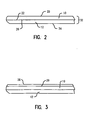
- the unwind stands 14, 16 are both situated adjacent from each other at the front of the extruder line and, as the first and second webs 10, 12 are unwound from their respective unwind stands 14, 16, the two webs are temporarily joined to one another along at least a portion of the length of the webs. This joining together is not permanent, however, in that the first web 10 is merely temporarily disposed on the second web 12 with the respective undersides 22, 26 of the webs contacting one another as seen in Fig. 2.
- the interfacial friction against any lateral sliding of the webs with respect to one another will be suffcient to keep them aligned.
- they may be temporarily adhered to one another by any of several methods. For instance, one or more edges of the two webs 10, 12 may be crimped together to hold the two webs 10, 12 together. The crimping may be accomplished at any point along the web path of wherein the webs 10, 12 are in contact with one another and prior to collection of the webs on a wind up stand using an edge crimping device 90.
- an adhesive may be applied to one or both of the web undersides 22, 26.
- the adhesive may be applied by a sprayer or other coating device 72.
- the coating or spray need only be applied just prior to making roll change on the windup stand.
- the webs 10,12 may also be joined by applying a static charge to one or both of the webs by a static charge device 30 prior to their contacting with each other.
- the static charges imparted to the webs 10,12 may then be used to temporarily join the first web to the second web.
- the static charge may preferably be applied across the entire width of the web or webs.
- the extrusion coating itself may be used to temporarily join the webs 10, 12 along one or more edges.
- the extrudate then tacks down the webs 10, 12 along the unaligned edge or edges.
- Any one or a combination ofthe above methods may be used to join the webs 10, 12 depending on the types of substrates employed.
- the temporarily joined webs are referred to collectively as the "composite web"32.
- the first web 10 be coated in the first extrusion station as a single web. Thereafter the second web 12 may be laid on to the first web 10 prior to entering the second extrusion station. In this manner, the second web 12 as well as the first web 10 may be unwound coating side up, thereby eliminating the need to invert the webs after the first extrusion station.
- first and second webs 10, 12 may be extrusion coated separately and thenjoined prior to being wound up together.
- the webs may be would up separately without ever being joined together using dual windup stands at the end of the multi-station extruder.
- first and second webs 10, 12 be temporarily joined as shown in Fig. 2 because this facilities collecting both finished webs on a single windup stand for later separation using a rewinder.
- the temporary joining also allows automatic roll changes to be made at the windup stand at or near full line speed.
- the webs 10, 12 need only be joined along a portion of the webs 10, 12.
- At least one layer of polymeric coating is disposed on the respective coating sides of the first and second webs 20, 24.
- the extruded coatings on the first and second webs 10,12 comprise a polymer selected from the group consisting of low density polyethylene (LDPE), polyolefin plastomers (POP), polyolefin elastomers (POE), linear low density polyethylene (LLDPE), high density polyethylene (HDPE), polypropylene (PP), ethylene methyl acrylate copolymer (EMA), ethylene butyl acrylate copolymer (EnBA), ethylene vinyl acetate copolymer (EVA), ethylene acrylic acid copolymer (EAA), ethylene methyl acrylic acid copolymer (EMAA), ionomoers such as SURLYN (which is understood to be a salt of poly (ethylene-co-methacrylic acid) available from Dupont), ethylene vinyl alcohol (EVOH), polyesters such as polyethylene terephthalate (PET), polyamides such as
- LDPE low density polyethylene
- POP polyolefin plastomers
- POE polyolefin elastomers
- LLDPE linear low density polyethylene
- HDPE high density polyethylene
- the thickness and coating weight of the polymer layer may also vary somewhat based on the particular application. However, the polymer coatings typically have a thickness of from about 5.334x10 -3 mm (0.21 mils) to about 0.0508 mm (2.0 mils) and a weight of from about 4.88 g/m 2 (3 lb/3000 ft 2 ) to about 47.20 g/m 2 (29 lb/3000 ft 2 ).
- first web 10 and / or the second web 12 may be surface treated, such as with a flame treatment or in an electrical corona discharge device 70, in order to oxidize the surface of the web and provide improved adhesion of the polymer coating to the web.
- the two webs 10, 12 are then conveyed to a first extrusion station 34 where the first polymer coating 36 is applied to the coating side of the first web 20 to provide a coated composite as illustrated in Fig. 3.
- polymer is supplied in the form of pellets of the polymer which are fed into a hopper and melted and mixed with any additives to provide a fluid, relatively uniform melt-extrudible mass.
- the molten material is then feed through an extrusion die 38 (seen in Fig. 6), and a resulting curtain of the extruded polymeric material 40 is extruded onto the composite web 32 as it passes through a nip in the extruder formed by a backup roll 42 and chill roll 44. Contacting with the chill roll 44 cools and solidifies the extrudate on the first coating side 20.
- the polymer melt is extruded at a feed rate of about 226.8 kg/h (500 lb/ h) to about 453.6 kg/h (1000 lb / h) while the composite web is conveyed at a speed of about 228.6 m/min (750 ft/min) to about 457.2 m/min (1500 feet/min).
- polymer feed rate, web width, and the web travel rate may be varied so as to provide thicker or thinner polymer coatings.
- the composite web 32 is conveyed onward to a second extrusion station 50.
- the first and second webs 10, 12 of the composite web 32 may be inverted or otherwise reoriented so that the second web 12 is properly aligned for coating at the second extrusion station 50. This may be accomplished using a set of turning bars 74.
- the second web coating side 24 is extrusion coated with a second polymer coating 52 as shown in Fig. 4.
- the molten polymer (along with any desired additives) is then feed through a second extrusion die and a curtain of the polymer is extruded onto the composite web as it passes through a nip in the extruder formed by a backup roll and a chill roll.
- Contacting with the chill roll cools and solidifies the second polymer coating extrudate 52 forming a layer of polymeric coating on the composite web 32.
- the second polymer melt is also extruded at a feed rate of about 226.8 kg/h (500 lb/ h) to about 453.6 kg/h (1000 lb/h) while the web is conveyed at a speed of about 228.6 m/min (750 ft/min) to about 457.2 m/min (1500 feet / min) to provide a polymer coating 52 having a thickness of about 0.0127 mm (0.5 mils).
- the two webs 10, 12, now each extrusion coated with a polymeric layer, may be collected.
- the webs 10, 12 may be separated from one another in line as seen in Fig. 5 and collected on separate wind up rolls directly after the second extrusion coating.
- the first and second webs 10, 12 be initially wound up together as a composite roll 54.
- the webs are preferably temporarily joined together, typically along the edges of the webs 10, 12.
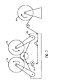
- the composite roll 54 may then be processed on a rewinder apparatus 80, shown in Fig. 7, which includes a trimmer 82 which cuts away the joined edges thereby separating the finished webs and allowing the webs 10,12 to be individually wound up on two separate windup rolls 84; 86.
- a dual or tandem station extruder may be used to approach or fulfill its rated capacity while applying one-side only coatings to substrate webs.
- the method allows the production speed of a dual extruder to be effectively doubled when used for one-side only coatings since two such products may now be extrusion-coated at once.
- the two substrates and their respective coatings may be the same.
- the invention may thus be used to dramatically increase the rate of production of a single type of extrusion coated substrate.
- the substrates and / or their polymer coating may also different.
- the invention provides a means to produce small batches of relatively low-volume coated substrate without halting production of much larger batches of a higher selling-volume product.
- Two webs of kraft paper each having a basis weight of about 51.27 g/m 2 (31.5 lbs / 3000 ft 2 ) and a caliper of about 0.0635 mm (2.5 mils) and having widths of about 80.645 cm (31.75 inches) (the first web) and 86.36 cm (34 inches) (the second web) respectively were unwound from separate rolls and conveyed to an extrusion coating system by a series of rollers and idlers. The two webs so combined were passed through a first extrusion station.
- a supply oflow density polyethylene EASTACOAT 6838-850P available from Eastman Chemical Co. of Longview, TX was heated to a temperature of about 321°C (610 °F) to provide a supply of molten extrudate.
- the molten extrudate was then feed through an extrusion die at a feed rate of about 113.4 kg/h (250 lb/h) to coat the exposed side of the first paperweb as it moved through the extrusion station.
- the extrudate was cooled by contacting with a chill roll forming a polymer coating over the kraft paper of the first web.
- the polymer coating weight was about 3.63 kg/riesmaschine (8 lbs /ream).
- a second extrusion coating was then applied to the second substrate web.
- a second supply of low density polyethylene was heated to a temperature of about 321°C (610 °F) to provide a supply of molten extrudate.
- the molten extrudate was then feed through an extrusion die at a feed rate of about 113.4 kg/h (250 lb/h) to coat the second paperweb side of the temporary composite as it moved through the second extrusion station.
- the extrudate was cooled by contacting with a chill roll to form a polymer coating over kraft paper of the second web.
- the polymer coating weight formed on the second web was also about 3.63 kg/riesmaschine (8 lbs/ream).
Landscapes
- Engineering & Computer Science (AREA)
- Mechanical Engineering (AREA)
- Physics & Mathematics (AREA)
- Thermal Sciences (AREA)
- Extrusion Moulding Of Plastics Or The Like (AREA)
- Application Of Or Painting With Fluid Materials (AREA)
- Coating Apparatus (AREA)
Abstract
Description
- The invention relates to a method for making webs and, in particular, to a new method for extrusion coating multiple webs simultaneously on a dual or tandem extruder system having multiple extruder stations.
- Webs such as paper and paperboard, polymer films, and metal foils which have been extrusion coated with a layer of polymer film are used in a myriad of applications such as packaging materials and so forth. In some instances, it is desireable to apply two extrusion coatings to a substrate web so that both sides of the substrate are coated with an extruded polymer layer. For these cases, so called "tandem" or dual extruders have been developed with multiple extrusion stations.
- However, cases requiring a coating on both sides of a web by means of a dual extruder may not be plentiful enough to maintain a tandem extruder at full capacity. In these instances, it has been common practice to simply shut down one of the extruder stations and operate the dual extruder in the same manner as a single station extruder. While this prevents the extruder from remaining completely idle, it still represents a significant waste of capital resources.
- It is therefore an object ofthe invention to provide a method for achieving more efficient and economical utilization of a dual or multiple station extruder.
- Another object of the invention is to provide a method for producing extrusion-coated substrates at a higher production rate.
- With regard to the foregoing and other objects and advantages, the present invention provides a method for extrusion coating multiple webs in an extruder system containing multiple extrusion stations as defined in appended claim 1. In a preferred embodiment, the method includes feeding a first web and a second web into a first extrusion station in the extruder system, where each web has a coating side and an underside. The webs are arranged one with respect to the other to form a temporary composite wherein respective undersides ofthe webs face each other and their respective coating sides face outwardly, away from each other. A first polymer coating is extruded on the coating side of the first web at the first extrusion station. The composite is fed to a second extrusion station following extrusion of the first polymer coating thereon. At the second extrusion station, a second polymer coating is extruded on the coating side of the second web of the composite. The extrusion coated first and second webs are then separated.
- It is also preferred in certain embodiments that the first and second webs comprise the same or similar materials. However, in other embodiments it is preferred that the first and second webs comprise substantially different materials. Preferred materials for the first and second webs include paper webs, polymer films, nonwoven fabrics, metal foils, and two or more thereof as a multi-ply web. The first and second webs preferably each have a basis weight of from about 11.39 g/m2 (7 lbs/3000 ft2) to about 203.43 g/m2 (125 lbs/3000 ft 2) and a caliper of from about 0.0127mm (0.5 mils) to about 0.254 mm (10 mils).
- Likewise, in certain embodiments it may be preferred that the first and second webs be extrusion coated with the same type of polymer. However in certain other embodiments, it may be preferred that the first and second webs are extrusion coated with different types of polymers. Preferably the first and second polymer coatings comprise a polymer selected from the group consisting of low density polyethylene (LDPE), polyolefin plastomers (POP), polyolefin elastomers (POE), linear low density polyethylene (LLDPE), high density polyethylene (HDPE), polypropylene (PP), ethylene methyl acrylate copolymer (EMA), ethylene butyl acrylate copolymer (EnBA), ethylene vinyl acetate copolymer (EVA), ethylene acrylic acid copolymer (EAA), ethylene methyl acrylic acid copolymer (EMAA), ionomoers such as SURLYN, ethylene vinyl alcohol (EVOH), polyesters such as polyethylene terephthalate (PET), and polyamides (PA) such as nylon-6 and nylon-6,6, and mixtures of two or more thereof.
- The invention therefore enables use of a dual station extruder to provide webs which are extrusion coated only on one side. In comparison to prior art, methods, the method of the invention essentially increases the production rate for such single-side coated webs by a factor of two or more.
- The above and other aspects and advantages of the invention will now be further described in conjunction with the accompanying drawings in which:
- Fig. 1 is an elevational view of a dual extruder system for use in practicing one embodiment of the present invention;
- Fig. 2 is an enlarged elevational view of two webs aligned on top of one another for processing in a dual extruder system according to one embodiment of the invention;
- Figs. 3 and 4 are elevational views of the webs of Fig. 2 illustrating the application of extrusion coatings to the webs according to the invention;
- Fig. 5 is an elevational view of the finished and separated webs according to one embodiment of the invention;
- Fig. 6 is an elevational view illustrating in greater detail a portion of an extruder system suitable for use in practicing one embodiment of the invention; and
- Fig. 7 is an elevational view of a web rewinder for separating two coated webs according to a preferred embodiment of the invention.
- The invention involves a method for extrusion coating multiple webs on dual tandem extruder systems having multiple extrusion stations. According to one embodiment, the method includes as an initial step providing a first web and a second web wherein each of the first and second webs have a coating side and an underside. The webs are superposed one with respect to the other to form a temporary composite wherein the respective coating sides face outward and the respective undersides face one another. A first polymer coating is extruded on the coating side of the first web at a first extrusion station. A second polymer coating is extruded on the coating side of the second web at a second extrusion station. The extrusion coated first and second webs are then separated.
- In the practice of the invention using, for example, a dual extruder two extrusion stations are typically arranged in series along the direction of travel of a substrate to be coated. Each extrusion station includes a hopper into which solid pellets of the polymeric coating material are feed, a heating zone wherein the polymer is melted prior to extrusion, and a slot or die through which the molten extrudate is feed and applied to the awaiting substrate web. One such dual extruder is available from Egan-Davis Standard of Somerville, New Jersey.
- Referring now to the drawings, various aspects of one embodiment a method according to the invention will now be described with reference to Fig. 1 wherein a
first web 10 and asecond web 12 are supplied to a dual extruder, preferably fromseparate unwind stands - As used herein, the term "first web" merely refers to the web which is coated with the first coating at the first extrusion station. Likewise, the term "second web" refers to the web which is coated with the second coating at the second extrusion station. The terms "first substrate or web" and "second substrate or web" are sometimes used in the extrusion coating art to designate the web from the unwind stand nearest the ground (the first web) and the web from the unwind stand located above the first web (the second web). The nomenclature used herein may not necessarily correspond to this convention sometimes used in the art.
- It is also to be noted that both unwind stands 14, 16 may be considered "primary" unwind stands as opposed to "secondary" unwind stands. Conventionally, when two webs are laminated together, a heavier, so-called "substrate" web is ordinarily referred to as the "primary" web taken from the primary unwind, and a lighter web is ordinarily called the "secondary" web taken from a secondary unwind stand, at least in conjunction with operation ofthe dual or multiple station extruder system. However, the first and second webs are preferably not ultimately laminated together according to the invention, at least in conjunction with operation of the dual or multiple station extruder system. Thus each web is, in essence, a primary web (according to trade nomenclature) and is taken from a primary unwind stand.
- The
first web 10 is provided as a substantially continuous web having two elongate, substantiallyparallel surfaces coating side 20 and the second as anunderside 22. Typically,such webs 10 have a basis weight of from about 11.39 g/m2 (7 lbs / 3000 ft2) to about 203.43 g/m2 (125 lbs / 3000 ft 2) and a thickness or caliper of from about 0.0127 mm (0.5 mil) to about 0.254 mm (10 mils). More preferably the basis weight is from about 24.42 g/m2 (15 lbs / 3000) ft 2 to about 146.47 g/m2 (90 lbs / 3000 ft 2) and the thickness ranges from about 0.0254 mm (1.0 mils) to about 0.2032 mm (8.0 mils). Among preferred materials for thefirst web 10 are paper webs (including paperboard webs), polymer films (including oriented polymer films), metal foils, nonwoven fabrics, and two or more thereof supplied as a multi-ply web. - Like the
first web 10, thesecond web 12 is provided as a substantially continuous web having two elongate, substantiallyparallel surfaces coating side 24 and the second as anunderside 26. Typicallysuch webs 12 have a basis weight of from about 11.39 g/m2 (7 lbs / 3000 ft 2) to about 203.43 g/m2 (125 lbs / 3000 ft 2) and a thickness or caliper of from about 0.0127 mm (0.5 mil) to about 0.254 mm (10 mils). More preferably the basis weight is from about 24.42 g/m2 (15 lbs / 3000 ft2) to about 146.47 g/m2 (90 lbs/3000 ft2) and the thickness ranges from about 0.0254 mm (1.0 mil) to about 0.2032 mm (8.0 mils). Preferred materials for thefirst substrate web 12 are paper webs (including paperboard webs), polymer films (including oriented polymer films), metal foils, nonwoven fabrics, and two or more thereof supplied as a multi-ply web. - The first and
second webs second substrates - The locations ofthe unwind stands 14, 16 relative to the extrusion stations may vary in the practice of the invention.
- In one preferred embodiment, the unwind stands 14, 16 are both situated adjacent from each other at the front of the extruder line and, as the first and
second webs first web 10 is merely temporarily disposed on thesecond web 12 with therespective undersides - Generally, the interfacial friction against any lateral sliding of the webs with respect to one another will be suffcient to keep them aligned. However, they may be temporarily adhered to one another by any of several methods. For instance, one or more edges of the two
webs webs webs edge crimping device 90. - Alternatively, an adhesive may be applied to one or both of the
web undersides other coating device 72. Advantageously the coating or spray need only be applied just prior to making roll change on the windup stand. - The
webs static charge device 30 prior to their contacting with each other. The static charges imparted to thewebs - In another preferred embodiment, the extrusion coating itself may be used to temporarily join the
webs webs webs webs webs - Any one or a combination ofthe above methods may be used to join the
webs - For convenience, the temporarily joined webs are referred to collectively as the "composite web"32.
- In certain other embodiments of the invention, it may be preferred that the
first web 10 be coated in the first extrusion station as a single web. Thereafter thesecond web 12 may be laid on to thefirst web 10 prior to entering the second extrusion station. In this manner, thesecond web 12 as well as thefirst web 10 may be unwound coating side up, thereby eliminating the need to invert the webs after the first extrusion station. - In another preferred embodiment, the first and
second webs - It is especially preferred, however, that the first and
second webs webs webs - At least one layer of polymeric coating is disposed on the respective coating sides of the first and
second webs second webs - Of the aforementioned polymers for the extrusion coating, particularly preferred are low density polyethylene (LDPE), polyolefin plastomers (POP), polyolefin elastomers (POE), linear low density polyethylene (LLDPE), high density polyethylene (HDPE), and mixtures thereof.
- The thickness and coating weight of the polymer layer may also vary somewhat based on the particular application. However, the polymer coatings typically have a thickness of from about 5.334x10⁻³ mm (0.21 mils) to about 0.0508 mm (2.0 mils) and a weight of from about 4.88 g/m2 (3 lb/3000 ft2) to about 47.20 g/m2 (29 lb/3000 ft2).
- Prior to the extrusion coating, either the
first web 10 and / or thesecond web 12 may be surface treated, such as with a flame treatment or in an electricalcorona discharge device 70, in order to oxidize the surface of the web and provide improved adhesion of the polymer coating to the web. The twowebs first extrusion station 34 where thefirst polymer coating 36 is applied to the coating side of thefirst web 20 to provide a coated composite as illustrated in Fig. 3. Preferably, polymer is supplied in the form of pellets of the polymer which are fed into a hopper and melted and mixed with any additives to provide a fluid, relatively uniform melt-extrudible mass. The molten material is then feed through an extrusion die 38 (seen in Fig. 6), and a resulting curtain of the extrudedpolymeric material 40 is extruded onto thecomposite web 32 as it passes through a nip in the extruder formed by abackup roll 42 and chillroll 44. Contacting with thechill roll 44 cools and solidifies the extrudate on thefirst coating side 20. - Typically the polymer melt is extruded at a feed rate of about 226.8 kg/h (500 lb/ h) to about 453.6 kg/h (1000 lb / h) while the composite web is conveyed at a speed of about 228.6 m/min (750 ft/min) to about 457.2 m/min (1500 feet/min). This results in a
polymeric coating 36 having a thickness of about 0.0127 mm (0.5 mils). However, it will appreciated that polymer feed rate, web width, and the web travel rate may be varied so as to provide thicker or thinner polymer coatings. - A suitable extrusion coating method, and materials for use therein, is described in commonly assigned Application Serial No. 09/978,524 entitled "Method for Extrusion Coating a Lightweight Web" filed October 16, 2001, having the same inventor as the present application and being filed on even date herewith, the disclosure of which is hereby incorporated by reference.
- After the molten extrudate cools on the
first web 10 to form afirst coating 36 thereon, thecomposite web 32 is conveyed onward to asecond extrusion station 50. During this movement, the first andsecond webs composite web 32 may be inverted or otherwise reoriented so that thesecond web 12 is properly aligned for coating at thesecond extrusion station 50. This may be accomplished using a set of turning bars 74. - At the
second extrusion station 50, the secondweb coating side 24 is extrusion coated with asecond polymer coating 52 as shown in Fig. 4. As with the first extrusion station, the molten polymer (along with any desired additives) is then feed through a second extrusion die and a curtain of the polymer is extruded onto the composite web as it passes through a nip in the extruder formed by a backup roll and a chill roll. Contacting with the chill roll cools and solidifies the secondpolymer coating extrudate 52 forming a layer of polymeric coating on thecomposite web 32. - Typically, the second polymer melt is also extruded at a feed rate of about 226.8 kg/h (500 lb/ h) to about 453.6 kg/h (1000 lb/h) while the web is conveyed at a speed of about 228.6 m/min (750 ft/min) to about 457.2 m/min (1500 feet / min) to provide a
polymer coating 52 having a thickness of about 0.0127 mm (0.5 mils). - Finally, the two
webs webs - However, most extrusion coatingmachines currently in operation only have one windup stand. Therefore, it is preferred that the first and
second webs composite roll 54. As noted above, when collected as a composite roll, the webs are preferably temporarily joined together, typically along the edges of thewebs composite roll 54 may then be processed on arewinder apparatus 80, shown in Fig. 7, which includes atrimmer 82 which cuts away the joined edges thereby separating the finished webs and allowing thewebs - By the use of the aforegoing method it will be appreciated that a dual or tandem station extruder may be used to approach or fulfill its rated capacity while applying one-side only coatings to substrate webs. Moreover, the method allows the production speed of a dual extruder to be effectively doubled when used for one-side only coatings since two such products may now be extrusion-coated at once.
- As noted, the two substrates and their respective coatings may be the same. The invention may thus be used to dramatically increase the rate of production of a single type of extrusion coated substrate. However, the substrates and / or their polymer coating may also different. Thus, the invention provides a means to produce small batches of relatively low-volume coated substrate without halting production of much larger batches of a higher selling-volume product.
- The following nonlimiting example illustrates various additional aspects of the invention.
- Two webs of kraft paper, each having a basis weight of about 51.27 g/m2 (31.5 lbs / 3000 ft2) and a caliper of about 0.0635 mm (2.5 mils) and having widths of about 80.645 cm (31.75 inches) (the first web) and 86.36 cm (34 inches) (the second web) respectively were unwound from separate rolls and conveyed to an extrusion coating system by a series of rollers and idlers. The two webs so combined were passed through a first extrusion station.
- In the first extrusion, a supply oflow density polyethylene, EASTACOAT 6838-850P available from Eastman Chemical Co. of Longview, TX was heated to a temperature of about 321°C (610 °F) to provide a supply of molten extrudate. The molten extrudate was then feed through an extrusion die at a feed rate of about 113.4 kg/h (250 lb/h) to coat the exposed side of the first paperweb as it moved through the extrusion station. The extrudate was cooled by contacting with a chill roll forming a polymer coating over the kraft paper of the first web. The polymer coating weight was about 3.63 kg/ries Papier (8 lbs /ream).
- Because of the slightly narrower width of the first web, the extrudate coating temporarily joined the two webs together.
- A second extrusion coating was then applied to the second substrate web. A second supply of low density polyethylene was heated to a temperature of about 321°C (610 °F) to provide a supply of molten extrudate. The molten extrudate was then feed through an extrusion die at a feed rate of about 113.4 kg/h (250 lb/h) to coat the second paperweb side of the temporary composite as it moved through the second extrusion station. The extrudate was cooled by contacting with a chill roll to form a polymer coating over kraft paper of the second web. The polymer coating weight formed on the second web was also about 3.63 kg/ries Papier (8 lbs/ream).
Claims (41)
- A method for extrusion coating multiple webs in an extruder system containing multiple extrusion stations comprising:feeding a first web and a second web into the extruder system, each web having a coating side;conveying the first web to a first extrusion station in the extruder system and extruding a first polymer coating on the coating side of the first web at the first extrusion station;laying the second web on to the first web to form a temporary composite;conveying the second web to a second extrusion station in the extruder system and extruding a second polymer coating on the coating side of the second web at the second extrusion station; andseparating the first and second webs of the temporary composite.
- The method of Claim 1 wherein the first and second web substrates comprise the same substrate material.
- The method of Claim 1 wherein the first and second web substrates comprise different substrate materials.
- The method of Claim 1 wherein the first and second webs are extrusion coated with the same type of polymer.
- The method of Claim 1 wherein the first and second webs are extrusion coated with different types of polymers.
- The method of Claim 1 wherein the first polymer coating comprises a polymer selected from the group consisting of selected from the group consisting of low density polyethylene (LDPE), polyolefin plastomer (POP), polyolefin elastomer (POE), linear low density polyethylene (LLDPE), high density polyethylene (HDPE), polypropylene (PP), ethylene methyl acrylate copolymer (EMA), ethylene butyl acrylate copolymer (EnBA), ethylene vinyl acetate copolymer (EVA), ethylene acrylic acid copolymer (EAA), ethylene methyl acrylic acid copolymer (EMAA), ionomoers, ethylene vinyl alcohol (EVOH), polyesters such as polyethylene terephthalate (PET), polyamides (PA), and mixtures of two or more thereof.
- The method of Claim 1 wherein the second polymer coating comprises a polymer selected from the group consisting of selected from the group consisting of low density polyethylene (LDPE), polyolefin plastomer (POP), polyolefin elastomer (POE), linear low density polyethylene (LLDPE), high density polyethylene (HDPE), polypropylene (PP), ethylene methyl acrylate copolymer (EMA), ethylene butyl acrylate copolymer (EnBA), ethylene vinyl acetate copolymer (EVA), ethylene acrylic acid copolymer (EAA), ethylene methyl acrylic acid copolymer (EMAA), ionomoers, ethylene vinyl alcohol (EVOH), polyesters such as polyethylene terephthalate (PET), polyamides (PA), and mixtures of two or more thereof.
- The method of Claim 1 wherein the first web is selected from the group consisting of paperwebs, polymer films, nonwoven fabrics, metal foils, and multi-ply webs comprising two or more thereof.
- The method of Claim 1 wherein the second web is selected from the group consisting of paperwebs, polymer films, nonwoven fabrics, metal foils and multi-ply webs comprising two or more thereof.
- The method of Claim 1 wherein the first web has a caliper of from about 0.0127 mm (0.5 mils) to about 0.254 mm (10 mils) and a basis weight of from about 11.39 g/m2 (7 lbs/3,000ft2) to about 203,43g/m2 (125 lbs/3,000ft2).
- The method of Claim 1 wherein the second web has a caliper of from about 0.0127 mm (0.5 mils) to about 0.254 mm (10 mils) and a basis weight of from about 11.39 g/m2 (7 lbs/3,000ft 2) to about 203.43 g/m2 (125 lbs/3,000 ft2).
- The method of Claim 1 further comprising the step of inverting the composite web prior to extruding the second polymer coating.
- (Amended) The method of Claim 1 wherein the coated first and second webs are initially wound up together on a single windup stand and thereafter separated.
- The method of Claim 13 wherein the coated first and second webs are temporarily joined together along at least one edge and are separated by trimming off the joined edge and winding the first and second webs onto separate windup rolls.
- The method of Claim 1 wherein the coated first and second webs are separated and collected on separate wind up rolls directly after the second polymer coating is extruded.
- The method of Claim 1 wherein the first polymer coating comprises a coextrusion of a plurality of polymer coatings.
- The method of Claim 1 wherein the second polymer coating comprises a coextrusion of a plurality of polymer coatings.
- The method of Claim 1 wherein the first and second webs are coated on their respective coating sides before they are separated.
- The method of Claim 1 wherein the first and second webs of the temporary composite are coated on their respective coating sides sequentially in the first and second coating stations.
- The method of Claim 1 wherein the first and second extruder stations comprise part of the same extruder and the respective coating sides of the first and second webs are coated substantially simultaneously in the same extruder.
- The method of Claim 1 wherein the first and second extruder stations comprise part of the same extruder and the respective coating sides of the first and second webs are coated in sequence in the same extruder.
- The method of Claim 1 wherein the first and second webs are in contact with each other in the temporary composite.
- The method of Claim 1 wherein one or both of the first and second webs is substantially uncoated on its coating side prior to having a polymer coating extruded thereon.
- The method of Claim 1 wherein one or both of the first and second webs contains on its coating side one or more layers of one or more materials coated thereon prior to having a polymer coating extruded thereon.
- The method for extrusion coating multiple webs in an extruder system containing multiple extrusion stations of claim 1 further comprising:feeding a first web and a second web into a first extrusion station in the extruder system, each web having a coating side and an underside, the webs being arranged one with respect to each other to form a temporary composite wherein the respective undersides of the webs face each other and their respective coating sides face outwardly, away from each other;extruding a first polymer coating on the coating side of the first web of the composite at the first extrusion station;feeding the composite to a second extrusion station following extrusion of the first polymer coating thereon;extruding a second polymer coating on the coating side of the second web of the composite at the second extrusion station; andseparating the extrusion coated first and second webs of the composite.
- The method of Claim 25 wherein the first and second webs comprise the same web material.
- The method of Claim 25 wherein the first and second webs comprise different web materials.
- The method of Claim 25 wherein the first and second webs are extrusion coated with the same type of polymer.
- The method of Claim 25 wherein the first and second webs are extrusion coated with different types of polymers.
- The method of Claim 25 wherein the first polymer is selected from the group consisting of selected from the group consisting of low density polyethylene (LDPE), polyolefin plastomer (POP), polyolefin elastomer (POE), linear low density polyethylene (LLDPE), high density polyethylene (HDPE), polypropylene (PP), ethylene methyl acrylate copolymer (EMA), ethylene butyl acrylate copolymer (EnBA), ethylene vinyl acetate copolymer (EVA), ethylene acrylic acid copolymer (EAA), ethylene methyl acrylic acid copolymer (EMAA), ionomoers, ethylene vinyl alcohol (EVOH), polyesters such as polyethylene terephthalate (PET), polyamides (PA), and mixtures of two or more thereof.
- The method of Claim 25 wherein the second polymer coating comprises a polymer selected from the group consisting of selected from the group consisting of low density polyethylene (LDPE), polyolefin plastomer (POP), polyolefin elastomer (POE), linear low density polyethylene (LLDPE), high density polyethylene (HDPE), polypropylene (PP), ethylene methyl acrylate copolymer (EMA), ethylene butyl acrylate copolymer (EnBA), ethylene vinyl acetate copolymer (EVA), ethylene acrylic acid copolymer (EAA), ethylene methyl acrylic acid copolymer (EMAA), ionomoers, ethylene vinyl alcohol (EVOH), polyesters such as polyethylene terephthalate (PET), polyamides (PA), and mixtures of two or more thereof.
- The method of Claim 25 wherein the first web is selected from the group consisting of paperwebs, polymer films, nonwoven fabrics, metal foils, and multi-ply webs comprising two or more thereof.
- The method of Claim 25 wherein the second web is selected from the group consisting of paperwebs, polymer films, nonwoven fabrics, metal foils, and multi-ply webs comprising two or more thereof.
- The method of Claim 25 wherein the first web has a caliper of from about 0.0127mm (0.5 mils) to about 0.254 mm (10 mils) and a basis weight of from about 11.39 g/m2 (7 lbs/3,000ft 2) to about 203.43 g/m2 (125 lbs/3,000 ft 2).
- The method of Claim 25 wherein the second web has a caliper of from about 0.0127 mm (0.5 mils) to about 0.254 mm (10 mils) and a basis weight of from about 11.39 g/m2 (7 lbs/3,000ft 2) to about 203.43 g/m2 (125 lbs/3,000 ft2).
- The method of Claim 25 further comprising the step of inverting the composite web prior to extruding the second polymer coating on the coating side of the second web of the composite.
- The method of Claim 25 wherein the coated first and second webs are wound up together on a single windup stand prior to being separated.
- The method of Claim 25 wherein the coated first and second webs are temporarily joined together along at least one edge and are separated by trimming off the joined edge and winding the first and second webs onto separate windup rolls.
- The method of Claim 25 wherein the coated first and second webs are separated and collected on separate wind up rolls after the second polymer coating is extruded.
- The method of Claim 25 wherein the first polymer coating comprises a coextrusion of a plurality of polymer coatings.
- The method of Claim 25 wherein the second polymer coating comprises a coextrusion of a plurality of polymer coatings.
Applications Claiming Priority (3)
| Application Number | Priority Date | Filing Date | Title |
|---|---|---|---|
| US978392 | 2001-10-16 | ||
| US09/978,392 US6656401B1 (en) | 2001-10-16 | 2001-10-16 | Method for extrusion coating multiple webs |
| PCT/US2002/032889 WO2003033237A1 (en) | 2001-10-16 | 2002-10-16 | Method for extrusion coating multiple webs |
Publications (3)
| Publication Number | Publication Date |
|---|---|
| EP1436136A1 EP1436136A1 (en) | 2004-07-14 |
| EP1436136A4 EP1436136A4 (en) | 2004-10-27 |
| EP1436136B1 true EP1436136B1 (en) | 2006-08-23 |
Family
ID=25526045
Family Applications (1)
| Application Number | Title | Priority Date | Filing Date |
|---|---|---|---|
| EP02801725A Expired - Lifetime EP1436136B1 (en) | 2001-10-16 | 2002-10-16 | Method for extrusion coating multiple webs |
Country Status (6)
| Country | Link |
|---|---|
| US (2) | US6656401B1 (en) |
| EP (1) | EP1436136B1 (en) |
| AT (1) | ATE337159T1 (en) |
| CA (1) | CA2463763C (en) |
| DE (1) | DE60214211D1 (en) |
| WO (1) | WO2003033237A1 (en) |
Families Citing this family (12)
| Publication number | Priority date | Publication date | Assignee | Title |
|---|---|---|---|---|
| GB9908602D0 (en) * | 1999-04-15 | 1999-06-09 | Northumbria Lyonnaise Technolo | Rehabilitation of water supply pipes |
| US7279198B1 (en) * | 2001-10-16 | 2007-10-09 | Thilmany Llc | Method for extrusion coating a lightweight web |
| US7735771B2 (en) * | 2004-06-30 | 2010-06-15 | The Procter & Gamble Company | Apparatus and method for the concurrent converting of multiple web materials |
| US8097109B2 (en) * | 2004-12-14 | 2012-01-17 | The Proctor & Gamble Company | Method for the concurrent converting of multiple web materials |
| CN106240991B (en) * | 2016-08-15 | 2019-08-23 | 广州松歌音响设备有限公司 | A kind of high intensity aviation case PE drawer preparation method and its product |
| ES2903371T3 (en) * | 2017-03-03 | 2022-04-01 | Csp Technologies Inc | Methods for dispensing and adhering to thermoplastic occluded polymeric substrates |
| CA3064832C (en) * | 2017-05-25 | 2024-04-09 | Magic Leap, Inc. | Double-sided imprinting |
| RU2745016C1 (en) * | 2017-06-23 | 2021-03-18 | Кимберли-Кларк Ворлдвайд, Инк. | System and method of applying glue to a moving belt |
| FR3071190B1 (en) | 2017-09-19 | 2021-02-19 | C E E Cie Europeenne Des Emballages Robert Schisler | PROCESS FOR MANUFACTURING CUPBOARDS COATED WITH BIODEGRADABLE VARNISH AND CUP MANUFACTURED ACCORDING TO THE PROCEDURE |
| SE542945C2 (en) * | 2018-10-03 | 2020-09-22 | Stora Enso Oyj | Polymer coated paper and paperboard |
| US11993092B2 (en) * | 2019-02-04 | 2024-05-28 | NFSC Holdings, LLC | UV/LED printing and finishing process |
| EP4188673B1 (en) | 2020-08-03 | 2024-12-04 | CSP Technologies, Inc. | Methods for dispensing and forming 3a molecular sieve hot melt entrained polymers onto substrates |
Family Cites Families (36)
| Publication number | Priority date | Publication date | Assignee | Title |
|---|---|---|---|---|
| US2686335A (en) | 1951-03-20 | 1954-08-17 | Frank R Gross | Plastic extrusion |
| US2690633A (en) | 1952-05-31 | 1954-10-05 | Harvey R Denton | Method of making packages |
| US2836851A (en) | 1955-09-09 | 1958-06-03 | Danielson Mfg Company | Apparatus for extrusion |
| GB1094351A (en) | 1964-06-04 | 1967-12-13 | Schmermund Alfred | Improvements in or relating to wrapping machines |
| US3505143A (en) * | 1966-03-10 | 1970-04-07 | American Can Co | Method of laminating sheet material by coating metal foil with a copolymer of ethylene and an ethylenically unsaturated carboxylic acid |
| US3650880A (en) * | 1968-11-20 | 1972-03-21 | Hooker Chemical Corp | Porous polyurethanes and method of manufacture |
| US3616020A (en) * | 1969-01-15 | 1971-10-26 | Standard Oil Co | Extrusion coating of a heat fusible foam sheet |
| US3632256A (en) | 1969-03-19 | 1972-01-04 | Union Carbide Corp | Extrusion-compounding apparatus |
| IT1023644B (en) | 1974-12-13 | 1978-05-30 | Wrapmatic Spa | EQUIPMENT FOR WRAPPING THE STACKS OF PAPER AND SIMILAR WITH SHEETS CUT FROM A PACKING TAPE AND TO ADJUST THE SIZE OF THE SHEETS TO THE SIZE OF THE REAMS |
| DE2639512C3 (en) * | 1976-09-02 | 1984-07-19 | Reifenhäuser KG, 5210 Troisdorf | Device for producing a thick sheet of thermoplastic material |
| US4207129A (en) * | 1977-11-21 | 1980-06-10 | Uop Inc. | Manufacture of conductive or semi-conductive elements by means of a continuous pultrusion process |
| US4233358A (en) | 1978-10-13 | 1980-11-11 | Clemead Limited | Method for the production of waterproof and like fabrics |
| US4302269A (en) * | 1979-10-10 | 1981-11-24 | Allied Corporation | Process of forming a fiber reinforced, stampable thermoplastic laminate |
| US4304522A (en) * | 1980-01-15 | 1981-12-08 | Pratt & Whitney Aircraft Of Canada Limited | Turbine bearing support |
| US4362585A (en) | 1981-08-31 | 1982-12-07 | Allied Corporation | Uniaxially oriented nylon film as carrier web for fiber reinforced plastics |
| DE3339924A1 (en) | 1983-11-04 | 1985-05-15 | Robert Bosch Gmbh, 7000 Stuttgart | PACKING MACHINE |
| US4837088A (en) * | 1985-02-05 | 1989-06-06 | Avery International Corporation | Coextruded core laminates |
| US4592938A (en) | 1985-03-25 | 1986-06-03 | Mobil Oil Corporation | Method of producing an internally reinforced thermoplastic film and film and articles produced therefrom |
| US4675016A (en) | 1985-10-22 | 1987-06-23 | Kimberly-Clark Corporation | Method for adhering curved tensioned elastic strips to a gatherable base material and the article produced |
| US4759816A (en) | 1986-07-07 | 1988-07-26 | Schoeller Technical Papers, Inc. | Strippable film for adhesive coating and laminating |
| US5028361A (en) * | 1987-11-09 | 1991-07-02 | Takeo Fujimoto | Method for molding a photosensitive composition |
| DE3907615A1 (en) | 1989-03-09 | 1990-09-13 | Focke & Co | DEVICE (PACKING MACHINE) FOR PACKING ITEMS OF DIFFERENT SIZES |
| US5005734A (en) | 1989-03-23 | 1991-04-09 | Colgate-Palmolive Company | Flexible pouch with reinforcement to facillitate pouring |
| DE4138138C2 (en) | 1991-10-19 | 2003-06-12 | Focke & Co | Device for producing large packs |
| CA2120330A1 (en) | 1991-11-01 | 1993-05-13 | Thomas M. Milbourn | Die coater for applying discrete coating patches |
| US5250348A (en) | 1991-12-09 | 1993-10-05 | International Paper Company | Improved wrapper paper for use in very low contact pressure applications |
| US5175978A (en) | 1991-12-09 | 1993-01-05 | International Paper Company | Method for wrapping products in very low contact pressure applications |
| FI920703A7 (en) | 1992-02-19 | 1993-08-20 | Borealis As | Method for making laminate |
| US5415910A (en) | 1992-10-19 | 1995-05-16 | International Paper Company | Container liner for dough products |
| US5691022A (en) | 1994-10-20 | 1997-11-25 | International Paper Company | Release liner base stock for printed films or labels |
| US6210767B1 (en) | 1994-10-20 | 2001-04-03 | International Paper Company | Release liner base stock for printed films or labels |
| FI100258B (en) | 1996-06-04 | 1997-10-31 | Fortum Heat And Gas Oy | Polylactide coated paper and method of making the same |
| US6150005A (en) | 1997-04-15 | 2000-11-21 | International Paper Company | Synthetic paper |
| US6080252A (en) | 1997-10-06 | 2000-06-27 | Illinois Tool Works Inc. | Zipper component and method for forming same |
| US6737113B2 (en) * | 2001-01-10 | 2004-05-18 | 3M Innovative Properties Company | Method for improving the uniformity of a wet coating on a substrate using pick-and-place devices |
| US6797319B2 (en) * | 2002-05-31 | 2004-09-28 | Kimberly-Clark Worldwide, Inc. | Application of foam to tissue products using a liquid permeable partition |
-
2001
- 2001-10-16 US US09/978,392 patent/US6656401B1/en not_active Expired - Lifetime
-
2002
- 2002-10-16 CA CA002463763A patent/CA2463763C/en not_active Expired - Fee Related
- 2002-10-16 DE DE60214211T patent/DE60214211D1/en not_active Expired - Lifetime
- 2002-10-16 EP EP02801725A patent/EP1436136B1/en not_active Expired - Lifetime
- 2002-10-16 AT AT02801725T patent/ATE337159T1/en not_active IP Right Cessation
- 2002-10-16 WO PCT/US2002/032889 patent/WO2003033237A1/en not_active Ceased
-
2003
- 2003-11-25 US US10/721,954 patent/US20040183223A1/en not_active Abandoned
Also Published As
| Publication number | Publication date |
|---|---|
| CA2463763A1 (en) | 2003-04-24 |
| WO2003033237A1 (en) | 2003-04-24 |
| CA2463763C (en) | 2007-10-02 |
| US6656401B1 (en) | 2003-12-02 |
| WO2003033237B1 (en) | 2004-05-21 |
| DE60214211D1 (en) | 2006-10-05 |
| US20040183223A1 (en) | 2004-09-23 |
| EP1436136A1 (en) | 2004-07-14 |
| EP1436136A4 (en) | 2004-10-27 |
| ATE337159T1 (en) | 2006-09-15 |
Similar Documents
| Publication | Publication Date | Title |
|---|---|---|
| CA2463766C (en) | Method for extrusion coating a lightweight web | |
| CA2463763C (en) | Method for extrusion coating multiple webs | |
| US5407702A (en) | Method for coating a metal strip | |
| CA2349246C (en) | Method for producing a multilayer coextrudate and a coextrudate produced according thereto | |
| EP0458484A2 (en) | Rubber-based adhesive tapes | |
| US20040154734A1 (en) | Apparatus and method for producing a thermoplastic resin continuous laminated sheet | |
| US7879420B2 (en) | Multi-layered liner, a multi-layered product which includes the release liner and a method for making the release liner | |
| MXPA00011916A (en) | Backing for duct tapes. | |
| US5747107A (en) | Method of applying a hot melt coating | |
| US20040013838A1 (en) | Method for producing a multilayer coextrudate and a film structure produced by this method | |
| AU2007262140B2 (en) | Production method and production device of organic resin coated metal plate | |
| US7833599B1 (en) | Method for producing a multilayer composite, and a composite produced in such a manner | |
| WO1998052737A1 (en) | Pvdc extrusion method and product | |
| FI88688C (en) | Foer farer Foer framstaellning av ytbehandlade thermoplastiska folier | |
| CA2181056A1 (en) | Pressure sensitive adhesive tape | |
| CN105792949A (en) | Polyvinylidene chloride coated substrates | |
| CA1216718A (en) | Method and apparatus for the production of a high- strength, tear-resistant polymer composite | |
| JPH01222920A (en) | Method for manufacturing co-extruded laminate article | |
| RU2632493C1 (en) | Production method of multilayer material by application of polymer coating by extrusion at calendering | |
| US20070122630A1 (en) | Co-extrusion or tandem extrusion of surface protection films | |
| JPH0811434B2 (en) | Manufacturing method of antibacterial film | |
| EP4214052A1 (en) | Knurled multilayer polyolefin films for use as antiadhesive interleaves, as well as process and technological line for manufacturing the same | |
| JPH04227781A (en) | New rubber-based self-adhesive tape | |
| CN121973538A (en) | Preparation equipment and method for dry intermittent coating type pole piece | |
| JPH04314542A (en) | Production of packaging material |
Legal Events
| Date | Code | Title | Description |
|---|---|---|---|
| PUAI | Public reference made under article 153(3) epc to a published international application that has entered the european phase |
Free format text: ORIGINAL CODE: 0009012 |
|
| 17P | Request for examination filed |
Effective date: 20040416 |
|
| AK | Designated contracting states |
Kind code of ref document: A1 Designated state(s): AT BE BG CH CY CZ DE DK EE ES FI FR GB GR IE IT LI LU MC NL PT SE SK TR |
|
| AX | Request for extension of the european patent |
Extension state: AL LT LV MK RO SI |
|
| A4 | Supplementary search report drawn up and despatched |
Effective date: 20040909 |
|
| RIC1 | Information provided on ipc code assigned before grant |
Ipc: 7B 32B 27/10 B Ipc: 7B 05D 1/26 B Ipc: 7B 29C 47/00 A Ipc: 7B 32B 31/00 B |
|
| 17Q | First examination report despatched |
Effective date: 20050214 |
|
| GRAP | Despatch of communication of intention to grant a patent |
Free format text: ORIGINAL CODE: EPIDOSNIGR1 |
|
| RAP1 | Party data changed (applicant data changed or rights of an application transferred) |
Owner name: THILMANY, LLC |
|
| GRAS | Grant fee paid |
Free format text: ORIGINAL CODE: EPIDOSNIGR3 |
|
| GRAA | (expected) grant |
Free format text: ORIGINAL CODE: 0009210 |
|
| AK | Designated contracting states |
Kind code of ref document: B1 Designated state(s): AT BE BG CH CY CZ DE DK EE ES FI FR GB GR IE IT LI LU MC NL PT SE SK TR |
|
| PG25 | Lapsed in a contracting state [announced via postgrant information from national office to epo] |
Ref country code: BE Free format text: LAPSE BECAUSE OF FAILURE TO SUBMIT A TRANSLATION OF THE DESCRIPTION OR TO PAY THE FEE WITHIN THE PRESCRIBED TIME-LIMIT Effective date: 20060823 Ref country code: SK Free format text: LAPSE BECAUSE OF FAILURE TO SUBMIT A TRANSLATION OF THE DESCRIPTION OR TO PAY THE FEE WITHIN THE PRESCRIBED TIME-LIMIT Effective date: 20060823 Ref country code: NL Free format text: LAPSE BECAUSE OF FAILURE TO SUBMIT A TRANSLATION OF THE DESCRIPTION OR TO PAY THE FEE WITHIN THE PRESCRIBED TIME-LIMIT Effective date: 20060823 Ref country code: CZ Free format text: LAPSE BECAUSE OF FAILURE TO SUBMIT A TRANSLATION OF THE DESCRIPTION OR TO PAY THE FEE WITHIN THE PRESCRIBED TIME-LIMIT Effective date: 20060823 Ref country code: CH Free format text: LAPSE BECAUSE OF FAILURE TO SUBMIT A TRANSLATION OF THE DESCRIPTION OR TO PAY THE FEE WITHIN THE PRESCRIBED TIME-LIMIT Effective date: 20060823 Ref country code: FI Free format text: LAPSE BECAUSE OF FAILURE TO SUBMIT A TRANSLATION OF THE DESCRIPTION OR TO PAY THE FEE WITHIN THE PRESCRIBED TIME-LIMIT Effective date: 20060823 Ref country code: AT Free format text: LAPSE BECAUSE OF FAILURE TO SUBMIT A TRANSLATION OF THE DESCRIPTION OR TO PAY THE FEE WITHIN THE PRESCRIBED TIME-LIMIT Effective date: 20060823 Ref country code: LI Free format text: LAPSE BECAUSE OF FAILURE TO SUBMIT A TRANSLATION OF THE DESCRIPTION OR TO PAY THE FEE WITHIN THE PRESCRIBED TIME-LIMIT Effective date: 20060823 Ref country code: IT Free format text: LAPSE BECAUSE OF FAILURE TO SUBMIT A TRANSLATION OF THE DESCRIPTION OR TO PAY THE FEE WITHIN THE PRESCRIBED TIME-LIMIT;WARNING: LAPSES OF ITALIAN PATENTS WITH EFFECTIVE DATE BEFORE 2007 MAY HAVE OCCURRED AT ANY TIME BEFORE 2007. THE CORRECT EFFECTIVE DATE MAY BE DIFFERENT FROM THE ONE RECORDED. Effective date: 20060823 |
|
| REG | Reference to a national code |
Ref country code: GB Ref legal event code: FG4D |
|
| RIC1 | Information provided on ipc code assigned before grant |
Ipc: B05D 1/26 20060101ALI20060718BHEP Ipc: B32B 27/10 20060101ALI20060718BHEP Ipc: B32B 27/00 20060101ALI20060718BHEP Ipc: B29C 47/00 20060101AFI20060718BHEP |
|
| REG | Reference to a national code |
Ref country code: CH Ref legal event code: EP |
|
| REG | Reference to a national code |
Ref country code: IE Ref legal event code: FG4D |
|
| REF | Corresponds to: |
Ref document number: 60214211 Country of ref document: DE Date of ref document: 20061005 Kind code of ref document: P |
|
| PG25 | Lapsed in a contracting state [announced via postgrant information from national office to epo] |
Ref country code: IE Free format text: LAPSE BECAUSE OF NON-PAYMENT OF DUE FEES Effective date: 20061016 |
|
| PG25 | Lapsed in a contracting state [announced via postgrant information from national office to epo] |
Ref country code: MC Free format text: LAPSE BECAUSE OF NON-PAYMENT OF DUE FEES Effective date: 20061031 |
|
| PG25 | Lapsed in a contracting state [announced via postgrant information from national office to epo] |
Ref country code: SE Free format text: LAPSE BECAUSE OF FAILURE TO SUBMIT A TRANSLATION OF THE DESCRIPTION OR TO PAY THE FEE WITHIN THE PRESCRIBED TIME-LIMIT Effective date: 20061123 Ref country code: DK Free format text: LAPSE BECAUSE OF FAILURE TO SUBMIT A TRANSLATION OF THE DESCRIPTION OR TO PAY THE FEE WITHIN THE PRESCRIBED TIME-LIMIT Effective date: 20061123 Ref country code: BG Free format text: LAPSE BECAUSE OF FAILURE TO SUBMIT A TRANSLATION OF THE DESCRIPTION OR TO PAY THE FEE WITHIN THE PRESCRIBED TIME-LIMIT Effective date: 20061123 |
|
| PG25 | Lapsed in a contracting state [announced via postgrant information from national office to epo] |
Ref country code: DE Free format text: LAPSE BECAUSE OF FAILURE TO SUBMIT A TRANSLATION OF THE DESCRIPTION OR TO PAY THE FEE WITHIN THE PRESCRIBED TIME-LIMIT Effective date: 20061124 |
|
| PG25 | Lapsed in a contracting state [announced via postgrant information from national office to epo] |
Ref country code: ES Free format text: LAPSE BECAUSE OF FAILURE TO SUBMIT A TRANSLATION OF THE DESCRIPTION OR TO PAY THE FEE WITHIN THE PRESCRIBED TIME-LIMIT Effective date: 20061204 |
|
| PG25 | Lapsed in a contracting state [announced via postgrant information from national office to epo] |
Ref country code: PT Free format text: LAPSE BECAUSE OF FAILURE TO SUBMIT A TRANSLATION OF THE DESCRIPTION OR TO PAY THE FEE WITHIN THE PRESCRIBED TIME-LIMIT Effective date: 20070125 |
|
| NLV1 | Nl: lapsed or annulled due to failure to fulfill the requirements of art. 29p and 29m of the patents act | ||
| REG | Reference to a national code |
Ref country code: CH Ref legal event code: PL |
|
| EN | Fr: translation not filed | ||
| PLBE | No opposition filed within time limit |
Free format text: ORIGINAL CODE: 0009261 |
|
| STAA | Information on the status of an ep patent application or granted ep patent |
Free format text: STATUS: NO OPPOSITION FILED WITHIN TIME LIMIT |
|
| GBPC | Gb: european patent ceased through non-payment of renewal fee |
Effective date: 20061123 |
|
| 26N | No opposition filed |
Effective date: 20070524 |
|
| PG25 | Lapsed in a contracting state [announced via postgrant information from national office to epo] |
Ref country code: GB Free format text: LAPSE BECAUSE OF NON-PAYMENT OF DUE FEES Effective date: 20061123 |
|
| PG25 | Lapsed in a contracting state [announced via postgrant information from national office to epo] |
Ref country code: GR Free format text: LAPSE BECAUSE OF FAILURE TO SUBMIT A TRANSLATION OF THE DESCRIPTION OR TO PAY THE FEE WITHIN THE PRESCRIBED TIME-LIMIT Effective date: 20061124 Ref country code: FR Free format text: LAPSE BECAUSE OF FAILURE TO SUBMIT A TRANSLATION OF THE DESCRIPTION OR TO PAY THE FEE WITHIN THE PRESCRIBED TIME-LIMIT Effective date: 20070511 |
|
| PG25 | Lapsed in a contracting state [announced via postgrant information from national office to epo] |
Ref country code: EE Free format text: LAPSE BECAUSE OF FAILURE TO SUBMIT A TRANSLATION OF THE DESCRIPTION OR TO PAY THE FEE WITHIN THE PRESCRIBED TIME-LIMIT Effective date: 20060823 |
|
| PG25 | Lapsed in a contracting state [announced via postgrant information from national office to epo] |
Ref country code: LU Free format text: LAPSE BECAUSE OF NON-PAYMENT OF DUE FEES Effective date: 20061016 Ref country code: TR Free format text: LAPSE BECAUSE OF FAILURE TO SUBMIT A TRANSLATION OF THE DESCRIPTION OR TO PAY THE FEE WITHIN THE PRESCRIBED TIME-LIMIT Effective date: 20060823 |
|
| PG25 | Lapsed in a contracting state [announced via postgrant information from national office to epo] |
Ref country code: FR Free format text: LAPSE BECAUSE OF FAILURE TO SUBMIT A TRANSLATION OF THE DESCRIPTION OR TO PAY THE FEE WITHIN THE PRESCRIBED TIME-LIMIT Effective date: 20060823 Ref country code: CY Free format text: LAPSE BECAUSE OF FAILURE TO SUBMIT A TRANSLATION OF THE DESCRIPTION OR TO PAY THE FEE WITHIN THE PRESCRIBED TIME-LIMIT Effective date: 20060823 |