EP1435555A2 - Robot localization system - Google Patents
Robot localization system Download PDFInfo
- Publication number
- EP1435555A2 EP1435555A2 EP03258247A EP03258247A EP1435555A2 EP 1435555 A2 EP1435555 A2 EP 1435555A2 EP 03258247 A EP03258247 A EP 03258247A EP 03258247 A EP03258247 A EP 03258247A EP 1435555 A2 EP1435555 A2 EP 1435555A2
- Authority
- EP
- European Patent Office
- Prior art keywords
- robot
- localization system
- radio wave
- docking station
- unit
- Prior art date
- Legal status (The legal status is an assumption and is not a legal conclusion. Google has not performed a legal analysis and makes no representation as to the accuracy of the status listed.)
- Granted
Links
Images


Classifications
-
- G—PHYSICS
- G05—CONTROLLING; REGULATING
- G05D—SYSTEMS FOR CONTROLLING OR REGULATING NON-ELECTRIC VARIABLES
- G05D1/00—Control of position, course or altitude of land, water, air, or space vehicles, e.g. automatic pilot
- G05D1/02—Control of position or course in two dimensions
-
- G—PHYSICS
- G05—CONTROLLING; REGULATING
- G05D—SYSTEMS FOR CONTROLLING OR REGULATING NON-ELECTRIC VARIABLES
- G05D1/00—Control of position, course or altitude of land, water, air, or space vehicles, e.g. automatic pilot
- G05D1/02—Control of position or course in two dimensions
- G05D1/021—Control of position or course in two dimensions specially adapted to land vehicles
- G05D1/0212—Control of position or course in two dimensions specially adapted to land vehicles with means for defining a desired trajectory
- G05D1/0225—Control of position or course in two dimensions specially adapted to land vehicles with means for defining a desired trajectory involving docking at a fixed facility, e.g. base station or loading bay
-
- G—PHYSICS
- G05—CONTROLLING; REGULATING
- G05D—SYSTEMS FOR CONTROLLING OR REGULATING NON-ELECTRIC VARIABLES
- G05D1/00—Control of position, course or altitude of land, water, air, or space vehicles, e.g. automatic pilot
- G05D1/02—Control of position or course in two dimensions
- G05D1/021—Control of position or course in two dimensions specially adapted to land vehicles
- G05D1/0255—Control of position or course in two dimensions specially adapted to land vehicles using acoustic signals, e.g. ultra-sonic singals
-
- G—PHYSICS
- G05—CONTROLLING; REGULATING
- G05D—SYSTEMS FOR CONTROLLING OR REGULATING NON-ELECTRIC VARIABLES
- G05D1/00—Control of position, course or altitude of land, water, air, or space vehicles, e.g. automatic pilot
- G05D1/02—Control of position or course in two dimensions
- G05D1/021—Control of position or course in two dimensions specially adapted to land vehicles
- G05D1/0268—Control of position or course in two dimensions specially adapted to land vehicles using internal positioning means
- G05D1/027—Control of position or course in two dimensions specially adapted to land vehicles using internal positioning means comprising intertial navigation means, e.g. azimuth detector
-
- G—PHYSICS
- G05—CONTROLLING; REGULATING
- G05D—SYSTEMS FOR CONTROLLING OR REGULATING NON-ELECTRIC VARIABLES
- G05D1/00—Control of position, course or altitude of land, water, air, or space vehicles, e.g. automatic pilot
- G05D1/02—Control of position or course in two dimensions
- G05D1/021—Control of position or course in two dimensions specially adapted to land vehicles
- G05D1/0268—Control of position or course in two dimensions specially adapted to land vehicles using internal positioning means
- G05D1/0272—Control of position or course in two dimensions specially adapted to land vehicles using internal positioning means comprising means for registering the travel distance, e.g. revolutions of wheels
-
- G—PHYSICS
- G05—CONTROLLING; REGULATING
- G05D—SYSTEMS FOR CONTROLLING OR REGULATING NON-ELECTRIC VARIABLES
- G05D1/00—Control of position, course or altitude of land, water, air, or space vehicles, e.g. automatic pilot
- G05D1/02—Control of position or course in two dimensions
- G05D1/021—Control of position or course in two dimensions specially adapted to land vehicles
- G05D1/0276—Control of position or course in two dimensions specially adapted to land vehicles using signals provided by a source external to the vehicle
- G05D1/028—Control of position or course in two dimensions specially adapted to land vehicles using signals provided by a source external to the vehicle using a RF signal
Definitions
- the present invention relates to a robot control, and more particularly, to a robot localization system for controlling a position and an orientation of a robot.
- Methods or apparatuses for localization of a robot uses dead-reckoning such as odometry and inertial navigation, for measuring a relative position of a robot; a global positioning system (GPS), active beacons, etc., for measuring an absolute position of a robot; and a magnetic compass for measuring an absolute orientation of a robot.
- dead-reckoning such as odometry and inertial navigation
- GPS global positioning system
- active beacons etc.
- a magnetic compass for measuring an absolute orientation of a robot.
- FIG. 1 is a diagram illustrating a conventional technique of detecting a position of a robot using three beacons. Positions A and B are detected using beacon 1 and beacon 2. Accordingly, beacon 3 is required to exactly detect the position A.
- the GPS is based on this principle. However, only positions without an orientation can be detected with this conventional technique.
- Korean Patent Publication No. 2000-66728 entitled “Robot Having Function of Detecting Sound Direction and Motion Direction and Function of Automatic Intelligent Charge and Method of Controlling the Same,” discloses an algorithm for measuring a sound direction and controlling the robot to move to an automatic charger.
- the charger When the charger generates a sound having a particular frequency, the robot detects a direction of the sound, locks on the detected direction, and docks to the charger. According to this technique, only a motion direction of a robot can be measured and controlled.
- Korean Patent Publication No. 2002-33303 entitled “Apparatus for Detecting Position of Robot in Robot Soccer Game,” discloses an apparatus for detecting a position of a robot using a plurality of beacons. Here, only positions without an orientation are detected.
- the present invention provides a method and apparatus for performing localization using a single beacon.
- the present invention also provides a robot localization system using a radio wave.
- a robot localization system including a robot, which moves within a predetermined space and performs predetermined tasks, and a docking station corresponding to a home position of the robot.
- the docking station includes a first transmitting unit, which transmits a sound wave to detect a position of the robot; and a second transmitting unit, which transmits a synchronizing signal right when the sound wave is transmitted.
- the robot includes a first receiving unit, which comprises at least two sound sensors receiving the sound wave incident onto the robot; a second receiving unit, which receives the synchronizing signal incident onto the robot; a distance calculation unit, which calculates a distance between the first transmitting unit and the first receiving unit using a difference between an instant of time when the synchronizing signal is received and an instant of time when the sound wave is received; and an incident angle calculation unit, which calculates an incident angle of the sound wave onto the robot using a difference between receiving times of the sound wave in the at least two sound sensors comprised in the first receiving unit.
- the sound wave is a supersonic wave.
- the robot localization system further includes an encoder, which measures a positional change between a previous position and a current position of the robot and a directional change between a previous orientation and a current orientation of the robot.
- the robot localization system further includes a state observer, which estimates a current position and a current orientation of the robot with respect to the docking station using the distance between the first transmitting unit and the first receiving unit, the incident angle of the sound wave, the positional change, and the directional change.
- the state observer includes a Kalman filter.
- the robot localization system further includes a unit for measuring an absolute azimuth of the robot.
- the robot localization system further includes a Kalman filter.
- a robot localization system including a robot and a docking station.
- the robot includes a first transmitter which transmits a first radio wave, a second receiver which receives a second radio wave, and a distance calculator which calculates a distance between the robot and the docking station.
- the docking station includes a first receiver which receives the first radio wave, and a second transmitter which transmits the second radio wave a predetermined period of time after the first radio wave is received.
- the distance calculator calculates the distance between the robot and the docking station using a difference between an instant of time when the first radio wave is transmitted and an instant of time when the second radio wave is received and a predetermined period of time from the reception of the first radio wave to the transmission of the second radio wave.
- the second receiver may include at least two sensors which receives the second radio wave, and the robot further includes an incident angle calculator which calculates an incident angle of the second radio wave onto the robot using a difference between receiving times of the second radio wave in the at least two sensors comprised in the second receiver.
- the robot localization system further includes an encoder, which measures a positional change between a previous position and a current position of the robot and a directional change between a previous orientation and a current orientation of the robot.
- the robot localization system further includes a state observer, which estimates a current position and a current orientation of the robot with respect to the docking station using the distance between the robot and the docking station, the incident angle of the second radio wave, the positional change, and the directional change.
- the state observer includes a Kalman filter.
- the robot localization system may further include a unit for measuring an absolute azimuth of the robot.
- the robot localization system further includes a Kalman filter.
- a robot localization system includes a robot, which moves within a predetermined space and performs predetermined tasks, and a docking station corresponding to a home position of the robot.
- FIG. 2 shows a coordinate system in which a positional relationship between the docking system and the robot is expressed as ( x , y , ⁇ ).
- coordinates ( x , y ) indicates a position of the robot (O') on a plane with the docking station (O) as the origin, and ⁇ indicates a direction toward which the robot is oriented in a current posture.
- the coordinates ( x , y ) can be replaced with coordinates ( L , ⁇ ) in a polar coordinate system.
- FIG. 3 is a block diagram of a robot localization system according to an embodiment of the present invention.
- the robot localization system includes a docking station 300 and a robot 310.
- the docking station 300 includes a first transmitting unit 301 and a second transmitting unit 302.
- the robot 310 includes a first receiving unit 311, a second receiving unit 312, an incident angle calculation unit 313, a distance calculation unit 314, an encoder 315, and a state observer 316.
- the first transmitting unit 301 transmits a signal, for example, a supersonic wave, in order to detect a position of the robot 310.
- the second transmitting unit 302 transmits a synchronizing signal right when the supersonic wave is transmitted in order to measure a distance between the docking station 300 and the robot 310 using a time difference between transmission and reception of the supersonic wave.
- the synchronizing signal is much faster than the supersonic wave and can be implemented by infrared (IR) or radio frequency (RF).
- the first receiving unit 311 includes two or more supersonic sensors which receive the supersonic wave which is transmitted from the docking station 300 and incident onto the robot 310.
- the second receiving unit 312 receives the synchronizing signal transmitted from the docking station 300 and incident onto the robot 310.
- the incident angle calculation unit 313 calculates an incident angle ⁇ of the supersonic wave onto the robot 310 using a difference between receiving times of the supersonic wave in the two or more supersonic sensors provided in the first receiving unit 311.
- the distance calculation unit 314 calculates a distance between the first transmitting unit 301 and the first receiving unit 311 using a difference between an instant of time when the synchronizing signal is received and an instant of time when the supersonic wave is received. In other words, a distance L between the docking station 300 and the robot 310 is calculated.
- a positional relationship between the docking station 300 and the robot 310 can be also expressed as ( L , ⁇ , ⁇ ).
- L indicates a distance between a reference position of the docking station 300 and the robot 310
- ⁇ indicates an incident angle of the supersonic wave with an x-axis of the robot 310, i.e., a reference axis of the robot 310
- ⁇ indicates a direction toward which the robot 310 is oriented.
- FIG. 5 illustrates a method of measuring a distance, which is performed by a robot localization system according to the present invention.
- the distance calculation unit 314 calculates a distance L according to Formula (1) using the supersonic wave and the synchronizing signal.
- L ⁇ t ⁇ c S
- c S indicates the speed of sound, i.e., 340 m/sec
- ⁇ t indicates a time difference between transmission of a supersonic wave from the docking station 300 and reception of the supersonic wave by the robot 310.
- the first transmitting unit 301 of the docking station 300 transmits a supersonic wave
- the second transmitting unit 302 transmits a synchronizing signal, for example, an RF or an IR signal.
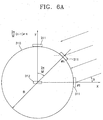
- FIGS. 6A and 6B illustrate a method by which the incident angle calculation unit 313 calculates an incident angle ⁇ using a supersonic wave received by the first receiving unit 311 of the robot 310.
- the incident angle calculation unit 313 calculates the incident angle ⁇ of a supersonic wave onto the robot 310 using a time difference between receiving times of the supersonic wave by the two or more supersonic sensors provided in the first receiving unit 311, for example, using Formula (2) or (3).
- FIG. 6A illustrates the use of Formula (2)
- FIG. 6B illustrates the use of Formula (3).
- t 1 indicates an instant of time when the supersonic wave is received by a first supersonic sensor
- t 2 indicates an instant of time when the supersonic wave is received by a second supersonic sensor
- R indicates a radius of a circle, which has the center (O' shown in FIG. 2) of the robot 310 as the origin and on the circumference of which the supersonic sensors are installed
- M indicates the number of supersonic sensors
- c indicates the speed of sound, i.e., 340 m/sec
- n indicates a sequence in which the supersonic wave is received by the supersonic sensors when the first supersonic sensor is fixed as a reference sensor for measurement of the incident angle ⁇ of the supersonic wave on the basis of the center O' of the robot 310.
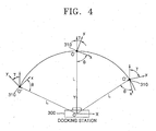
- the robot 310 can determine the position and the direction of the docking station 300 from ( L , ⁇ ) using Formulae (1) through (3). However, the docking station 300 cannot determine the current position of the robot 300 only from ( L , ⁇ ). Referring to FIG. 4, many positions can be defined by ( L , ⁇ ). Only when ⁇ is set, the current position of the robot 310 can be determined, and simultaneously, the direction toward the robot 310 is oriented can be also determined. Hereinafter, it will be explained how to estimate ⁇ with encoder signals using the Kalman filter.
- the encoder 315 measures a change between a previous position and a current position and a change between a previous orientation and a current orientation. Then, the encoder 315 informs the robot 310 of the measured changes, and based on this the robot 310 controls its position or orientation. It is possible to currently localize the robot 310 by integrating differences given by changes in a position and an orientation of the robot 310 using the encoder 315. If an integration error does not occur, localization of the robot 310 is possible only with the encoder 315. As in a case of using an odometer, such localization using the encoder 315 is roughly accurate during a short period of time, but integration errors accumulate quickly due to sampling errors.
- the state observer 316 estimates the current position and orientation of the robot 310 with respect to the docking station 300 using the distance L , incident angle ⁇ , and the positional change and the orientation change measured by the encoder 315.
- the state observer 316 may include a Kalman filter.
- FIG. 7 is a block diagram of an example of a Kalman filter.
- the Kalman filter calculates an optimized output and a state estimation vector using a known input value u and a measurement value y n containing a measurement noise n .
- a position and an orientation of the robot 310 can be determined using Formula (4), based on the coordinate system having the docking station 300 as the origin, as presented in FIGS. 2 and 4.
- v ( t ) indicates a linear velocity command
- ⁇ ( t ) indicates an angular velocity command
- ⁇ ( t ) indicates noise in the discrete system
- E(*) indicates an average of *
- Q ( t ) indicates a covariance matrix of noise
- Modeling for measurement of the robot localization system of the present invention is expressed using Formula (6).
- T indicates a sampling time.
- ⁇ ( kT ) indicates measurement noise of the encoder 315 or the first receiving unit 311.
- x ( kT ), y ( kT ), and ⁇ ( kT ) indicate position and orientation values of the robot 310 measured using the encoder 315.
- L ( kT ) and ⁇ ( kT ) indicate a distance between the robot 310 and the docking station 300 and direction of the docking station 300 measured using the first receiving unit 311.
- ⁇ ( kT ) can be replaced with a value measured by this absolute azimuth measurement unit.
- FIG. 8 is a block diagram of a robot localization system according to another embodiment of the present invention.
- the robot localization system includes a robot motion controller 800, a measurement unit 810, and a state observer 820.
- the state observer 820 includes a system estimator 821, an observation estimator 822, an adder 823, a Kalman filter 824, and a unit time delay section 825.
- the robot motion controller 800 outputs a linear velocity command ( ⁇ ( t )) and an angular velocity command ( ⁇ ( t )) in order to change a position and an orientation of the robot.
- the system estimator 821 outputs a system estimation vector X and ( k + 1, k ).
- the system estimation vector X and ( k + 1, k ) is expressed using Formula (7).
- L ( k ) indicates a transformation matrix which linearizes U ( k ).
- the observation estimator 822 converts the system estimation vector X and ( k + 1, k ) into an observation estimation vector Z and ( k + 1).
- the observation estimation vector Z and ( k + 1) is expressed as Formula (8) when the sampling time is 1.
- Z ( k +1) G ( X ( k +1, k )) + ⁇ ( k )
- the measurement unit 810 outputs a position measurement value Z ( k +1) of the robot using an encoder 811, a supersonic sensor 812, etc.
- the adder 823 adds the position measurement value Z ( k +1) and the observation estimation vector Z and ( k +1).
- the Kalman filter 824 calculates an optimal estimation vector X and ( k+ 1, k+ 1) using Formula (9).
- X ( k +1, k +1) X ( k +1, k ) + K ( k +1) ⁇ [ Z ( k +1) - Z ( k +1)]
- the Kalman filter 824 uses parameters shown in Formula (10).
- the unit time delay section 825 updates a time step in a discrete analysis based on time-marching. In other words, due to the operation of the unit time delay section 825, a current optimal estimation vector X and ( k + 1, k + 1) becomes a previous optimal estimation vector X and ( k , k ), which is used in a subsequent calculation.
- FIG. 9 is a block diagram of a robot localization system according to another embodiment of the present invention.
- the robot localization system includes a docking station 900 and a robot 910.
- the docking station 900 includes a first transmitting unit 901 and a second transmitting unit 902.
- the robot 910 includes a first receiving unit 911, a second receiving unit 912, an incident angle calculation unit 913, a distance calculation unit 914, an absolute azimuth measurement unit 915, and a state observer 916.
- the absolute azimuth measurement unit 915 is used.
- the encoder 917 measures a change between a previous position and a current position and a change between a previous orientation and a current orientation.
- the absolute azimuth measurement unit 915 measures an absolute azimuth ( ⁇ ) of the robot 910.
- the absolute azimuth measurement unit 915 may be implemented as a gyroscope or a magnetic compass. Since the absolute azimuth measured by, for example, a gyroscope contains measurement noise, the state observer 916 including a Kalman filter is used to obtain an optimal output.
- FIG. 10 is a diagram illustrating a method of measuring a distance between a robot and a docking station using a radio wave.
- L ⁇ t ⁇ c L
- c L indicates the speed of light
- ⁇ t indicates a time difference between an instant of time when the robot transmits a first radio wave and an instant of time when the docking station receives the first radio wave.
- the robot transmits a first radio wave S1, and then the docking station receives the first radio wave S1 after the time difference ⁇ t .
- a predetermined period of time T M after receiving the first radio wave S1 the docking station transmits a second radio wave S2.
- the robot receives the second radio wave S2 after the time difference ⁇ t .
- T round a time from the transmission of the first radio wave S1 to the reception of the second radio wave S2
- ⁇ t can be defined by Formula (12).
- T round is a measured value
- T M is a known value
- the robot includes a first transmitter, a second receiver, and a distance calculator
- the docking station includes a first receiver and a second transmitter.
- the first transmitter transmits a first radio wave.
- the first transmitter is disposed at an appropriate position, for example, the position denoted by the reference numeral 312 shown in FIG. 5, in the robot.
- the second receiver receives a second radio wave.
- the second receiver is disposed at an appropriate position, for example, the position denoted by the reference numeral 311 shown in FIG. 5, in the robot.
- the second receiver includes only a single radio wave sensor. Accordingly, the second receiver is disposed at only one appropriate position among the positions denoted by the reference numeral 311.
- the distance calculator calculates, for example, the distance L between the robot 310 and the docking station 300 shown in FIG. 5, using Formulae (11) and (12).
- the first receiver receives the first radio wave.
- the first receiver is disposed at an appropriate position, for example, the position denoted by the reference numeral 301 shown in FIG. 5, in the docking station.
- the second transmitter transmits the second radio wave.
- the second transmitter is disposed at an appropriate position, for example, the position denoted by the reference numeral 302 shown in FIG. 5, in the docking station.
- the robot may include at least two radio wave sensors in the second receiver in order to determine an orientation of the docking station.
- each radio wave sensor may be disposed at one of the positions denoted by the reference numeral 311 shown in FIG. 5.
- a method of calculating an incident angle of the second radio wave onto the robot using a radio wave is the same as the method of calculating an incident angle of a supersonic wave using Formulae (2) and (3), described with reference to FIGS. 6A and 6B.
- the structure and operations of the robot localization system using a radio wave are the same as those of the robot localization system using a supersonic wave, with the exception that a radio wave is used instead of a supersonic wave.
- a position and a direction toward a stationary docking station can be measured using a single beacon provided in the docking station and a supersonic sensor provided in a robot.
- robot localization using a radio wave is also possible.
Abstract
Description
- The present invention relates to a robot control, and more particularly, to a robot localization system for controlling a position and an orientation of a robot.
- Methods or apparatuses for localization of a robot uses dead-reckoning such as odometry and inertial navigation, for measuring a relative position of a robot; a global positioning system (GPS), active beacons, etc., for measuring an absolute position of a robot; and a magnetic compass for measuring an absolute orientation of a robot. Approaches for robot localization are described in detail in "Mobile Robot Positioning Sensors and Techniques" by J. Borenstein, H.R. Everett, L. Feng, and D. Wehe.
- FIG. 1 is a diagram illustrating a conventional technique of detecting a position of a robot using three beacons. Positions A and B are detected using beacon 1 and beacon 2. Accordingly, beacon 3 is required to exactly detect the position A. The GPS is based on this principle. However, only positions without an orientation can be detected with this conventional technique.
- Korean Patent Publication No. 2000-66728, entitled "Robot Having Function of Detecting Sound Direction and Motion Direction and Function of Automatic Intelligent Charge and Method of Controlling the Same," discloses an algorithm for measuring a sound direction and controlling the robot to move to an automatic charger. When the charger generates a sound having a particular frequency, the robot detects a direction of the sound, locks on the detected direction, and docks to the charger. According to this technique, only a motion direction of a robot can be measured and controlled.
- Korean Patent Publication No. 2002-33303, entitled "Apparatus for Detecting Position of Robot in Robot Soccer Game," discloses an apparatus for detecting a position of a robot using a plurality of beacons. Here, only positions without an orientation are detected.
- The present invention provides a method and apparatus for performing localization using a single beacon.
- The present invention also provides a robot localization system using a radio wave.
- According to an aspect of the present invention, there is provided a robot localization system including a robot, which moves within a predetermined space and performs predetermined tasks, and a docking station corresponding to a home position of the robot. The docking station includes a first transmitting unit, which transmits a sound wave to detect a position of the robot; and a second transmitting unit, which transmits a synchronizing signal right when the sound wave is transmitted. The robot includes a first receiving unit, which comprises at least two sound sensors receiving the sound wave incident onto the robot; a second receiving unit, which receives the synchronizing signal incident onto the robot; a distance calculation unit, which calculates a distance between the first transmitting unit and the first receiving unit using a difference between an instant of time when the synchronizing signal is received and an instant of time when the sound wave is received; and an incident angle calculation unit, which calculates an incident angle of the sound wave onto the robot using a difference between receiving times of the sound wave in the at least two sound sensors comprised in the first receiving unit. The sound wave is a supersonic wave.
- Preferably, the robot localization system further includes an encoder, which measures a positional change between a previous position and a current position of the robot and a directional change between a previous orientation and a current orientation of the robot.
- Preferably, the robot localization system further includes a state observer, which estimates a current position and a current orientation of the robot with respect to the docking station using the distance between the first transmitting unit and the first receiving unit, the incident angle of the sound wave, the positional change, and the directional change. The state observer includes a Kalman filter.
- Preferably, the robot localization system further includes a unit for measuring an absolute azimuth of the robot. Preferably, the robot localization system further includes a Kalman filter.
- According to another aspect of the present invention, there is provided a robot localization system including a robot and a docking station. The robot includes a first transmitter which transmits a first radio wave, a second receiver which receives a second radio wave, and a distance calculator which calculates a distance between the robot and the docking station. The docking station includes a first receiver which receives the first radio wave, and a second transmitter which transmits the second radio wave a predetermined period of time after the first radio wave is received. The distance calculator calculates the distance between the robot and the docking station using a difference between an instant of time when the first radio wave is transmitted and an instant of time when the second radio wave is received and a predetermined period of time from the reception of the first radio wave to the transmission of the second radio wave.
- The second receiver may include at least two sensors which receives the second radio wave, and the robot further includes an incident angle calculator which calculates an incident angle of the second radio wave onto the robot using a difference between receiving times of the second radio wave in the at least two sensors comprised in the second receiver.
- The robot localization system further includes an encoder, which measures a positional change between a previous position and a current position of the robot and a directional change between a previous orientation and a current orientation of the robot.
- The robot localization system further includes a state observer, which estimates a current position and a current orientation of the robot with respect to the docking station using the distance between the robot and the docking station, the incident angle of the second radio wave, the positional change, and the directional change. Here, the state observer includes a Kalman filter.
- The robot localization system may further include a unit for measuring an absolute azimuth of the robot. Here, the robot localization system further includes a Kalman filter.
- The above and other features and advantages of the present invention will become more apparent by describing in detail preferred embodiments thereof with reference to the attached drawings in which:
- FIG. 1 is a diagram illustrating a conventional technique of detecting a position of a robot using three beacons;
- FIG. 2 shows a coordinate system in which a positional relationship between a docking system and a robot is expressed as (x, y, γ);
- FIG. 3 is a block diagram of a robot localization system according to an embodiment of the present invention;
- FIG. 4 shows a coordinate system in which a positional relationship between a docking system and a robot is expressed as (L, , γ);
- FIG. 5 illustrates a method of measuring a distance, which is performed by a robot localization system according to an embodiment of the present invention;
- FIGS. 6A and 6B illustrate a method of calculating an incident angle using a supersonic wave received by a first receiving unit in a robot;
- FIG. 7 is a block diagram of an example of a Kalman filter;
- FIG. 8 is a block diagram of a robot localization system according to another embodiment of the present invention;
- FIG. 9 is a block diagram of a robot localization system according to still another embodiment of the present invention; and
- FIG. 10 is a diagram illustrating a method of measuring a distance between a robot and a docking station using a radio wave.
-
- Hereinafter, the structure and operation of a robot localization system according to the present invention will be described in detail with reference to the attached drawings.
- A robot localization system according to the present invention includes a robot, which moves within a predetermined space and performs predetermined tasks, and a docking station corresponding to a home position of the robot.
- FIG. 2 shows a coordinate system in which a positional relationship between the docking system and the robot is expressed as (x, y, γ). Here, coordinates (x, y) indicates a position of the robot (O') on a plane with the docking station (O) as the origin, and γ indicates a direction toward which the robot is oriented in a current posture. The coordinates (x, y) can be replaced with coordinates (L, ) in a polar coordinate system.
- FIG. 3 is a block diagram of a robot localization system according to an embodiment of the present invention. The robot localization system includes a docking station 300 and a robot 310. Preferably, the docking station 300 includes a first transmitting unit 301 and a second transmitting unit 302. Preferably, the robot 310 includes a first receiving unit 311, a second receiving unit 312, an incident angle calculation unit 313, a distance calculation unit 314, an encoder 315, and a state observer 316.
- The first transmitting unit 301 transmits a signal, for example, a supersonic wave, in order to detect a position of the robot 310. The second transmitting unit 302 transmits a synchronizing signal right when the supersonic wave is transmitted in order to measure a distance between the docking station 300 and the robot 310 using a time difference between transmission and reception of the supersonic wave. The synchronizing signal is much faster than the supersonic wave and can be implemented by infrared (IR) or radio frequency (RF).
- The first receiving unit 311 includes two or more supersonic sensors which receive the supersonic wave which is transmitted from the docking station 300 and incident onto the robot 310. The second receiving unit 312 receives the synchronizing signal transmitted from the docking station 300 and incident onto the robot 310. The incident angle calculation unit 313 calculates an incident angle of the supersonic wave onto the robot 310 using a difference between receiving times of the supersonic wave in the two or more supersonic sensors provided in the first receiving unit 311. The distance calculation unit 314 calculates a distance between the first transmitting unit 301 and the first receiving unit 311 using a difference between an instant of time when the synchronizing signal is received and an instant of time when the supersonic wave is received. In other words, a distance L between the docking station 300 and the robot 310 is calculated.
- As shown in FIG. 4, a positional relationship between the docking station 300 and the robot 310 can be also expressed as (L, , γ). Here, L indicates a distance between a reference position of the docking station 300 and the robot 310, indicates an incident angle of the supersonic wave with an x-axis of the robot 310, i.e., a reference axis of the robot 310, and γ indicates a direction toward which the robot 310 is oriented.
- FIG. 5 illustrates a method of measuring a distance, which is performed by a robot localization system according to the present invention. The distance calculation unit 314 calculates a distance L according to Formula (1) using the supersonic wave and the synchronizing signal.
- Here, cS indicates the speed of sound, i.e., 340 m/sec, and Δt indicates a time difference between transmission of a supersonic wave from the docking station 300 and reception of the supersonic wave by the robot 310.
- Referring to FIG. 5, the first transmitting unit 301 of the docking station 300 transmits a supersonic wave, and simultaneously, the second transmitting unit 302 transmits a synchronizing signal, for example, an RF or an IR signal. Then, the robot 310 can measure the time difference Δt between receiving time of the synchronizing signal by the second receiving unit 312 and receiving time of the supersonic wave by the first receiving unit 311. Accordingly, the distance L can be calculated by multiplying the time difference Δt by the speed of sound c (=340 m/sec).
- FIGS. 6A and 6B illustrate a method by which the incident angle calculation unit 313 calculates an incident angle using a supersonic wave received by the first receiving unit 311 of the robot 310. The incident angle calculation unit 313 calculates the incident angle of a supersonic wave onto the robot 310 using a time difference between receiving times of the supersonic wave by the two or more supersonic sensors provided in the first receiving unit 311, for example, using Formula (2) or (3). FIG. 6A illustrates the use of Formula (2), and FIG. 6B illustrates the use of Formula (3).

- Here, t 1 indicates an instant of time when the supersonic wave is received by a first supersonic sensor, t 2 indicates an instant of time when the supersonic wave is received by a second supersonic sensor, R indicates a radius of a circle, which has the center (O' shown in FIG. 2) of the robot 310 as the origin and on the circumference of which the supersonic sensors are installed, M indicates the number of supersonic sensors, and c indicates the speed of sound, i.e., 340 m/sec, n indicates a sequence in which the supersonic wave is received by the supersonic sensors when the first supersonic sensor is fixed as a reference sensor for measurement of the incident angle of the supersonic wave on the basis of the center O' of the robot 310.
- However, when 2π / M (n-1) = π, for example, when two supersonic sensors are provided in the first receiving unit 311, the incident angle is calculated according to Formula (3).

- The robot 310 can determine the position and the direction of the docking station 300 from (L, ) using Formulae (1) through (3). However, the docking station 300 cannot determine the current position of the robot 300 only from (L, ). Referring to FIG. 4, many positions can be defined by (L, ). Only when γ is set, the current position of the robot 310 can be determined, and simultaneously, the direction toward the robot 310 is oriented can be also determined. Hereinafter, it will be explained how to estimate γ with encoder signals using the Kalman filter.
- The encoder 315 measures a change between a previous position and a current position and a change between a previous orientation and a current orientation. Then, the encoder 315 informs the robot 310 of the measured changes, and based on this the robot 310 controls its position or orientation. It is possible to currently localize the robot 310 by integrating differences given by changes in a position and an orientation of the robot 310 using the encoder 315. If an integration error does not occur, localization of the robot 310 is possible only with the encoder 315. As in a case of using an odometer, such localization using the encoder 315 is roughly accurate during a short period of time, but integration errors accumulate quickly due to sampling errors.
- The state observer 316 estimates the current position and orientation of the robot 310 with respect to the docking station 300 using the distance L, incident angle , and the positional change and the orientation change measured by the encoder 315. The state observer 316 may include a Kalman filter.
- FIG. 7 is a block diagram of an example of a Kalman filter. When the dynamic equation of a system is given as y=Cx+Du+Hw, the Kalman filter calculates an optimized output and a state estimation vector using a known input value u and a measurement value yn containing a measurement noise n.
- In the robot localization system shown in FIG. 3, a position and an orientation of the robot 310 can be determined using Formula (4), based on the coordinate system having the docking station 300 as the origin, as presented in FIGS. 2 and 4.

- Here, v(t) indicates a linear velocity command, and ω(t) indicates an angular velocity command.
- Accordingly, a discrete system modeling of the robot localization system of the present invention is expressed using Formula (5).

- Here, η(t) indicates noise in the discrete system, E(*) indicates an average of *, and Q(t) indicates a covariance matrix of noise.
- Modeling for measurement of the robot localization system of the present invention is expressed using Formula (6).

- Here, T indicates a sampling time. µ(kT) indicates measurement noise of the encoder 315 or the first receiving unit 311. x(kT), y(kT), and γ(kT) indicate position and orientation values of the robot 310 measured using the encoder 315. L(kT) and (kT) indicate a distance between the robot 310 and the docking station 300 and direction of the docking station 300 measured using the first receiving unit 311.
- When a unit for measuring an absolute azimuth of the robot 310, for example, a gyroscope or a magnetic compass, is provided, γ(kT) can be replaced with a value measured by this absolute azimuth measurement unit.
- FIG. 8 is a block diagram of a robot localization system according to another embodiment of the present invention. The robot localization system includes a robot motion controller 800, a measurement unit 810, and a state observer 820. The state observer 820 includes a system estimator 821, an observation estimator 822, an adder 823, a Kalman filter 824, and a unit time delay section 825.
- The robot motion controller 800 outputs a linear velocity command (ν(t)) and an angular velocity command (ω(t)) in order to change a position and an orientation of the robot. In response to the linear velocity command and the angular velocity command, the system estimator 821 outputs a system estimation vector X and(k + 1, k). The system estimation vector X and(k + 1, k) is expressed using Formula (7).

- Here, L(k) indicates a transformation matrix which linearizes U(k).
- The observation estimator 822 converts the system estimation vector X and(k + 1, k) into an observation estimation vector Z and(k + 1). The observation estimation vector Z and(k + 1) is expressed as Formula (8) when the sampling time is 1.
- The measurement unit 810 outputs a position measurement value Z(k+1) of the robot using an encoder 811, a supersonic sensor 812, etc. The adder 823 adds the position measurement value Z(k+1) and the observation estimation vector Z and(k+1). The Kalman filter 824 calculates an optimal estimation vector X and(k+1,k+1) using Formula (9).
- To calculate the optimal estimation vector X and(k+1,k +1), the Kalman filter 824 uses parameters shown in Formula (10).

- The unit time delay section 825 updates a time step in a discrete analysis based on time-marching. In other words, due to the operation of the unit time delay section 825, a current optimal estimation vector X and(k + 1, k + 1) becomes a previous optimal estimation vector X and(k,k), which is used in a subsequent calculation.
- FIG. 9 is a block diagram of a robot localization system according to another embodiment of the present invention. The robot localization system includes a docking station 900 and a robot 910. Preferably, the docking station 900 includes a first transmitting unit 901 and a second transmitting unit 902. Preferably, the robot 910 includes a first receiving unit 911, a second receiving unit 912, an incident angle calculation unit 913, a distance calculation unit 914, an absolute azimuth measurement unit 915, and a state observer 916. Instead of the encoder 315 shown in FIG. 3, the absolute azimuth measurement unit 915 is used.
- The encoder 917 measures a change between a previous position and a current position and a change between a previous orientation and a current orientation.
- The absolute azimuth measurement unit 915 measures an absolute azimuth (γ) of the robot 910. The absolute azimuth measurement unit 915 may be implemented as a gyroscope or a magnetic compass. Since the absolute azimuth measured by, for example, a gyroscope contains measurement noise, the state observer 916 including a Kalman filter is used to obtain an optimal output.
- In the above embodiments, the structure and operations of a robot localization system using a sound wave, and particularly, a supersonic wave have been described.
- Hereinafter, an embodiment of a robot localization system using a radio wave will be described. FIG. 10 is a diagram illustrating a method of measuring a distance between a robot and a docking station using a radio wave.
- Here, cL indicates the speed of light, and Δt indicates a time difference between an instant of time when the robot transmits a first radio wave and an instant of time when the docking station receives the first radio wave.
- Referring to FIG. 10, the robot transmits a first radio wave S1, and then the docking station receives the first radio wave S1 after the time difference Δt. A predetermined period of time TM after receiving the first radio wave S1, the docking station transmits a second radio wave S2. Then, the robot receives the second radio wave S2 after the time difference Δt. Accordingly, when a time from the transmission of the first radio wave S1 to the reception of the second radio wave S2 is represented by Tround , Δt can be defined by Formula (12).
- Here, in view of the robot, Tround is a measured value, and TM is a known value.
- To measure a distance between the robot and the docking station using Formulae (11) and (12), the robot includes a first transmitter, a second receiver, and a distance calculator, and the docking station includes a first receiver and a second transmitter.
- The first transmitter transmits a first radio wave. The first transmitter is disposed at an appropriate position, for example, the position denoted by the reference numeral 312 shown in FIG. 5, in the robot.
- The second receiver receives a second radio wave. The second receiver is disposed at an appropriate position, for example, the position denoted by the reference numeral 311 shown in FIG. 5, in the robot. In order to measure only a distance, the second receiver includes only a single radio wave sensor. Accordingly, the second receiver is disposed at only one appropriate position among the positions denoted by the reference numeral 311.
- The distance calculator calculates, for example, the distance L between the robot 310 and the docking station 300 shown in FIG. 5, using Formulae (11) and (12).
- The first receiver receives the first radio wave. The first receiver is disposed at an appropriate position, for example, the position denoted by the reference numeral 301 shown in FIG. 5, in the docking station.
- The second transmitter transmits the second radio wave. The second transmitter is disposed at an appropriate position, for example, the position denoted by the reference numeral 302 shown in FIG. 5, in the docking station.
- In a robot localization system using a radio wave according to another embodiment of the present invention, the robot may include at least two radio wave sensors in the second receiver in order to determine an orientation of the docking station. For example, each radio wave sensor may be disposed at one of the positions denoted by the reference numeral 311 shown in FIG. 5. A method of calculating an incident angle of the second radio wave onto the robot using a radio wave is the same as the method of calculating an incident angle of a supersonic wave using Formulae (2) and (3), described with reference to FIGS. 6A and 6B.
- The structure and operations of the robot localization system using a radio wave are the same as those of the robot localization system using a supersonic wave, with the exception that a radio wave is used instead of a supersonic wave.
- As described above, according to a robot localization system of the present invention, a position and a direction toward a stationary docking station can be measured using a single beacon provided in the docking station and a supersonic sensor provided in a robot. In addition, it is possible to localize the robot with respect to the docking station using an additional Kalman filter. In addition, robot localization using a radio wave is also possible.
- Although a few embodiments of the present invention have been shown and described, it will be appreciated by those skilled in the art that changes may be made in these elements without departing from the principles of the invention, the scope of which is defined in the appended claims and their equivalents.
Claims (14)
- A robot localization system including a robot, which moves within a predetermined space and performs predetermined tasks, and a docking station corresponding to a home position of the robot,
the docking station comprising:the robot comprising:a first transmitting unit, which transmits a sound wave to detect a position of the robot; anda second transmitting unit, which transmits a synchronizing signal right when the sound wave is transmitted,a first receiving unit, which comprises at least two sound sensors receiving the sound wave incident onto the robot;a second receiving unit, which receives the synchronizing signal incident onto the robot;a distance calculation unit, which calculates a distance between the first transmitting unit and the first receiving unit using a difference between an instant of time when the synchronizing signal is received and an instant of time when the sound wave is received; andan incident angle calculation unit, which calculates an incident angle of the sound wave onto the robot using a difference between receiving times of the sound wave in the at least two sound sensors comprised in the first receiving unit. - The robot localization system of claim 1, wherein the sound wave is a supersonic wave.
- The robot localization system of claim 1, further comprising an encoder, which measures a positional change between a previous position and a current position of the robot and a directional change between a previous orientation and a current orientation of the robot.
- The robot localization system of claim 3, further comprising a state observer, which estimates a current position and a current orientation of the robot with respect to the docking station using the distance between the first transmitting unit and the first receiving unit, the incident angle of the sound wave, the positional change, and the directional change.
- The robot localization system of claim 4, wherein the state observer comprises a Kalman filter which estimates the orientation of the robot using the positional and directional changes measured by the encoder.
- The robot localization system of claim 1, further comprising a unit for measuring an absolute azimuth of the robot.
- The robot localization system of claim 6, further comprising a Kalman filter which filters measurement noise of the unit for measuring the absolute azimuth of the robot.
- A robot localization system including a robot and a docking station,
the robot comprising:the docking station comprising:a first transmitter which transmits a first radio wave;a second receiver which receives a second radio wave; anda distance calculator which calculates a distance between the robot and the docking station,wherein the distance calculator calculates the distance between the robot and the docking station using a difference between an instant of time when the first radio wave is transmitted and an instant of time when the second radio wave is received and a predetermined period of time from the reception of the first radio wave to the transmission of the second radio wave.a first receiver which receives the first radio wave; anda second transmitter which transmits the second radio wave a predetermined period of time after the first radio wave is received, - The robot localization system of claim 8, wherein the second receiver comprises at least two sensors which receives the second radio wave, and the robot further comprises an incident angle calculator which calculates an incident angle of the second radio wave onto the robot using a difference between receiving times of the second radio wave in the at least two sensors comprised in the second receiver.
- The robot localization system of claim 9, further comprising an encoder, which measures a positional change between a previous position and a current position of the robot and a directional change between a previous orientation and a current orientation of the robot.
- The robot localization system of claim 10, further comprising a state observer, which estimates a current position and a current orientation of the robot with respect to the docking station using the distance between the robot and the docking station, the incident angle of the second radio wave, the positional change, and the directional change.
- The robot localization system of claim 11, wherein the state observer comprises a Kalman filter which estimates the orientation of the robot using the positional and directional changes measured by the encoder.
- The robot localization system of claim 9, further comprising a unit for measuring an absolute azimuth of the robot.
- The robot localization system of claim 13, further comprising a Kalman filter which filters measurement noise of the unit for measuring the absolute azimuth of the robot.
Applications Claiming Priority (2)
| Application Number | Priority Date | Filing Date | Title |
|---|---|---|---|
| KR2002087154 | 2002-12-30 | ||
| KR20020087154 | 2002-12-30 |
Publications (3)
| Publication Number | Publication Date |
|---|---|
| EP1435555A2 true EP1435555A2 (en) | 2004-07-07 |
| EP1435555A3 EP1435555A3 (en) | 2004-10-27 |
| EP1435555B1 EP1435555B1 (en) | 2013-12-25 |
Family
ID=32501458
Family Applications (1)
| Application Number | Title | Priority Date | Filing Date |
|---|---|---|---|
| EP03258247.0A Expired - Fee Related EP1435555B1 (en) | 2002-12-30 | 2003-12-30 | Robot localization system |
Country Status (4)
| Country | Link |
|---|---|
| US (2) | US7970491B2 (en) |
| EP (1) | EP1435555B1 (en) |
| JP (1) | JP2004212400A (en) |
| KR (1) | KR100561855B1 (en) |
Cited By (9)
| Publication number | Priority date | Publication date | Assignee | Title |
|---|---|---|---|---|
| WO2005093536A1 (en) * | 2004-03-22 | 2005-10-06 | BSH Bosch und Siemens Hausgeräte GmbH | Surface treating system |
| DE102004014273A1 (en) * | 2004-03-22 | 2005-10-13 | BSH Bosch und Siemens Hausgeräte GmbH | Surface machining system |
| EP1621948A2 (en) * | 2004-07-30 | 2006-02-01 | Lg Electronics Inc. | Apparatus and method for calling mobile robot |
| GB2419686A (en) * | 2004-10-27 | 2006-05-03 | Samsung Kwangju Electronics Co | System for returning a robot cleaner to an external charging apparatus |
| DE102007036231A1 (en) | 2007-08-02 | 2009-02-05 | BSH Bosch und Siemens Hausgeräte GmbH | Method for controlling mobility of mobile device to stationary device, particularly for battery driven dust collecting robot to battery-charging station, involves emitting two guide signals with partially overlapping radiation lobes |
| DE102007036230A1 (en) | 2007-08-02 | 2009-02-12 | BSH Bosch und Siemens Hausgeräte GmbH | A method and system for determining the position of a mobile device with respect to a stationary device, in particular an accumulator-powered dust collection robot with respect to a rechargeable battery charger |
| DE102011011932A1 (en) | 2010-02-18 | 2012-03-15 | Alois Rüschen | Navigation system for e.g. position determination of security patrol robot, has ultrasound transmitting stations positioned in surface, where ultrasonic transmission range of station is partially overlapped with that of adjacent station |
| CN105511456A (en) * | 2014-09-23 | 2016-04-20 | 苏州宝时得电动工具有限公司 | Control method for automatic walking equipment, and automatic work system |
| CN113093092A (en) * | 2021-04-01 | 2021-07-09 | 哈尔滨工程大学 | Underwater robust self-adaptive single beacon positioning method |
Families Citing this family (56)
| Publication number | Priority date | Publication date | Assignee | Title |
|---|---|---|---|---|
| KR100561855B1 (en) | 2002-12-30 | 2006-03-16 | 삼성전자주식회사 | Robot localization system |
| KR100486737B1 (en) * | 2003-04-08 | 2005-05-03 | 삼성전자주식회사 | Method and apparatus for generating and tracing cleaning trajectory for home cleaning robot |
| KR100928964B1 (en) * | 2003-04-15 | 2009-11-26 | 삼성전자주식회사 | Mobile robot docking station return method and device |
| KR100565227B1 (en) * | 2003-12-22 | 2006-03-30 | 엘지전자 주식회사 | Position recognition apparatus and method for mobile robot |
| KR100600487B1 (en) * | 2004-10-12 | 2006-07-13 | 삼성광주전자 주식회사 | Robot cleaner cordinates compensating method and robot cleaner system using the same |
| KR100633160B1 (en) * | 2004-12-17 | 2006-10-11 | 삼성전자주식회사 | Robot system capable of recognizing position and direction using beacon |
| JP4569565B2 (en) * | 2005-01-12 | 2010-10-27 | パナソニック電工株式会社 | Flow line measurement system |
| KR100621096B1 (en) * | 2005-02-01 | 2006-09-13 | 삼성전자주식회사 | Method and apparatus for correcting systematic error using magnetic field |
| JP2007132938A (en) * | 2005-11-07 | 2007-05-31 | Samsung Electronics Co Ltd | Robot, and method of estimating position of robot |
| KR100834761B1 (en) * | 2005-11-23 | 2008-06-05 | 삼성전자주식회사 | Method and apparatus for reckoning position of moving robot |
| KR101234797B1 (en) * | 2006-04-04 | 2013-02-20 | 삼성전자주식회사 | Robot and method for localization of the robot using calculated covariance |
| KR100772912B1 (en) * | 2006-05-16 | 2007-11-05 | 삼성전자주식회사 | Robot using absolute azimuth and method for mapping by the robot |
| KR100860966B1 (en) * | 2006-06-05 | 2008-09-30 | 삼성전자주식회사 | Method for estimating position of moving robot and apparatus thereof |
| KR100791383B1 (en) * | 2006-07-07 | 2008-01-07 | 삼성전자주식회사 | Method for estimating relative position between moving robot and transmitter and apparatus thereof |
| WO2008010269A1 (en) * | 2006-07-19 | 2008-01-24 | Panasonic Electric Works Co., Ltd. | System for detecting position of mobile object |
| KR100794728B1 (en) * | 2006-08-11 | 2008-01-15 | 주식회사 나인티시스템 | System and method of measuring robot in localization |
| KR100815570B1 (en) * | 2006-12-06 | 2008-03-20 | 삼성광주전자 주식회사 | System for robot cleaner and control methord thereof |
| JP4569586B2 (en) * | 2007-03-09 | 2010-10-27 | パナソニック電工株式会社 | Flow line measurement system |
| JP4569585B2 (en) * | 2007-03-09 | 2010-10-27 | パナソニック電工株式会社 | Flow line measurement system |
| JP4569587B2 (en) * | 2007-03-09 | 2010-10-27 | パナソニック電工株式会社 | Flow line measurement system |
| JP4569588B2 (en) * | 2007-03-09 | 2010-10-27 | パナソニック電工株式会社 | Flow line measurement system |
| WO2009011542A1 (en) * | 2007-07-18 | 2009-01-22 | Lg Electronics Inc. | Mobile robot and controlling method thereof |
| US20090140926A1 (en) * | 2007-12-04 | 2009-06-04 | Elden Douglas Traster | System and method for localization utilizing dynamically deployable beacons |
| KR101415879B1 (en) * | 2008-01-04 | 2014-07-07 | 삼성전자 주식회사 | Method and apparatus for docking moving robot |
| KR101198773B1 (en) | 2008-01-23 | 2012-11-12 | 삼성전자주식회사 | Returning Method of Robot Cleaner System |
| CN102065738A (en) | 2008-06-02 | 2011-05-18 | 熊津豪威株式会社 | Robot cleaner system and method for controlling a robot cleaner |
| US8942862B2 (en) * | 2010-03-17 | 2015-01-27 | Husqvarna Ab | Method and system for guiding a robotic garden tool to a predetermined position |
| CN201840423U (en) * | 2010-10-11 | 2011-05-25 | 洋通工业股份有限公司 | Charging stand of self-walking dust collector |
| KR101263482B1 (en) * | 2010-11-02 | 2013-05-13 | 한국과학기술원 | Dynamic localization method and apparatus for mobile robots |
| US9069357B2 (en) * | 2012-06-15 | 2015-06-30 | Asustek Computer Inc. | Navigation device and method for auto-docking of a robot |
| JP6319736B2 (en) * | 2013-09-19 | 2018-05-09 | 株式会社Ihi | Sensor orientation control method and apparatus |
| DE102014212408A1 (en) * | 2014-06-27 | 2015-12-31 | Robert Bosch Gmbh | Autonomous working device |
| KR101697857B1 (en) * | 2015-04-08 | 2017-01-18 | 엘지전자 주식회사 | Moving robot and method for recognizing a location of the same |
| DE102015109775B3 (en) | 2015-06-18 | 2016-09-22 | RobArt GmbH | Optical triangulation sensor for distance measurement |
| DE102015114883A1 (en) | 2015-09-04 | 2017-03-09 | RobArt GmbH | Identification and localization of a base station of an autonomous mobile robot |
| DE102015119501A1 (en) | 2015-11-11 | 2017-05-11 | RobArt GmbH | Subdivision of maps for robot navigation |
| DE102015119865B4 (en) | 2015-11-17 | 2023-12-21 | RobArt GmbH | Robot-assisted processing of a surface using a robot |
| DE102015121666B3 (en) | 2015-12-11 | 2017-05-24 | RobArt GmbH | Remote control of a mobile, autonomous robot |
| DE102016102644A1 (en) | 2016-02-15 | 2017-08-17 | RobArt GmbH | Method for controlling an autonomous mobile robot |
| CN106444748A (en) * | 2016-09-08 | 2017-02-22 | 南京阿凡达机器人科技有限公司 | Method and system for automatic charging of robot |
| EP3590014B1 (en) | 2017-03-02 | 2021-11-17 | Robart GmbH | Method for controlling an autonomous, mobile robot |
| CN107685334B (en) * | 2017-09-27 | 2024-04-02 | 歌尔股份有限公司 | Service robot charging method and service robot |
| KR102051046B1 (en) * | 2017-11-21 | 2019-12-02 | 유진기술 주식회사 | Following system for solar panel cleaning robot of mobile robot and method thereof |
| US10382094B2 (en) * | 2017-11-28 | 2019-08-13 | International Business Machines Corporation | Cable tracking by electromagnetic emission |
| TWI665068B (en) * | 2018-02-06 | 2019-07-11 | 世擘股份有限公司 | Automatic cleaning device and automatic charging method |
| US11320828B1 (en) | 2018-03-08 | 2022-05-03 | AI Incorporated | Robotic cleaner |
| US11254002B1 (en) | 2018-03-19 | 2022-02-22 | AI Incorporated | Autonomous robotic device |
| US11454981B1 (en) | 2018-04-20 | 2022-09-27 | AI Incorporated | Versatile mobile robotic device |
| US11340079B1 (en) | 2018-05-21 | 2022-05-24 | AI Incorporated | Simultaneous collaboration, localization, and mapping |
| US11548159B1 (en) | 2018-05-31 | 2023-01-10 | AI Incorporated | Modular robot |
| US11199853B1 (en) | 2018-07-11 | 2021-12-14 | AI Incorporated | Versatile mobile platform |
| US11287824B2 (en) | 2018-11-19 | 2022-03-29 | Mobile Industrial Robots A/S | Detecting a location of an autonomous device |
| CN111413960A (en) * | 2018-12-19 | 2020-07-14 | 深圳市优必选科技有限公司 | Cruising method and device based on virtual track and terminal equipment |
| US10809734B2 (en) | 2019-03-13 | 2020-10-20 | Mobile Industrial Robots A/S | Route planning in an autonomous device |
| US11592299B2 (en) | 2020-03-19 | 2023-02-28 | Mobile Industrial Robots A/S | Using static scores to control vehicle operations |
| US11835949B2 (en) | 2020-11-24 | 2023-12-05 | Mobile Industrial Robots A/S | Autonomous device safety system |
Citations (4)
| Publication number | Priority date | Publication date | Assignee | Title |
|---|---|---|---|---|
| US4758691A (en) * | 1986-01-23 | 1988-07-19 | Zellweger Uster Ltd. | Apparatus for determining the position of a movable object |
| EP0502249A2 (en) * | 1991-03-04 | 1992-09-09 | TZN Forschungs- und Entwicklungszentrum Unterlüss GmbH | Method for detecting vehicle rotation rates and device for performing the method |
| EP0732641A2 (en) * | 1995-03-15 | 1996-09-18 | Technologietransfer-Anstalt, T e t r a | Tracking control for a driverless vehicle |
| US5652593A (en) * | 1994-09-29 | 1997-07-29 | Von Schrader Company | Method and apparatus for guiding a machine |
Family Cites Families (42)
| Publication number | Priority date | Publication date | Assignee | Title |
|---|---|---|---|---|
| EP0142594B1 (en) | 1983-10-26 | 1989-06-28 | Automax Kabushiki Kaisha | Control system for mobile robot |
| JPS61156413A (en) * | 1984-12-28 | 1986-07-16 | Yamatake Honeywell Co Ltd | Automatic follow-up device |
| US4679152A (en) | 1985-02-20 | 1987-07-07 | Heath Company | Navigation system and method for a mobile robot |
| FR2594586B1 (en) * | 1986-02-14 | 1988-04-29 | Bull Sa | METHOD FOR MOVING A MOBILE SYSTEM IN RELATION TO AN INFORMATION MEDIUM AND DEVICE FOR IMPLEMENTING IT |
| US4777416A (en) * | 1986-05-16 | 1988-10-11 | Denning Mobile Robotics, Inc. | Recharge docking system for mobile robot |
| US4809936A (en) | 1987-10-08 | 1989-03-07 | The United States Of America As Represented By The Administrator Of The National Aeronautics And Space Administration | Space module assembly apparatus with docking alignment flexibility and restraint |
| US5307271A (en) | 1990-09-28 | 1994-04-26 | The United States Of America As Represented By The Secretary Of The Navy | Reflexive teleoperated control system for a remotely controlled vehicle |
| US5491670A (en) * | 1993-01-21 | 1996-02-13 | Weber; T. Jerome | System and method for sonic positioning |
| JPH08129420A (en) * | 1994-11-02 | 1996-05-21 | Nippon Telegr & Teleph Corp <Ntt> | Direction and position controller for tunnel robot and constitution method for n-dimensional linear discrete time system probability model |
| DE19521358C1 (en) | 1995-06-12 | 1996-09-05 | Siemens Ag | Slip detection system for 3-wheeled autonomous mobile unit |
| US5948043A (en) * | 1996-11-08 | 1999-09-07 | Etak, Inc. | Navigation system using GPS data |
| JPH10240342A (en) | 1997-02-28 | 1998-09-11 | Minolta Co Ltd | Autonomous traveling vehicle |
| US5991525A (en) * | 1997-08-22 | 1999-11-23 | Voyan Technology | Method for real-time nonlinear system state estimation and control |
| DE19738163A1 (en) | 1997-09-01 | 1999-03-11 | Siemens Ag | Method for docking an autonomous mobile unit using a beacon |
| SE523080C2 (en) | 1998-01-08 | 2004-03-23 | Electrolux Ab | Docking system for self-propelled work tools |
| US6133876A (en) * | 1998-03-23 | 2000-10-17 | Time Domain Corporation | System and method for position determination by impulse radio |
| IL124413A (en) | 1998-05-11 | 2001-05-20 | Friendly Robotics Ltd | System and method for area coverage with an autonomous robot |
| EP1098587A1 (en) | 1998-07-31 | 2001-05-16 | Volker Sommer | Household robot for the automatic suction of dust from the floor surfaces |
| JP2000056006A (en) | 1998-08-14 | 2000-02-25 | Minolta Co Ltd | Position recognizing device for mobile |
| US6254035B1 (en) | 1998-12-10 | 2001-07-03 | The United States Of America As Represented By The Administrator Of The National Aeronautics And Space Administration | Synchronized docking system |
| US6338013B1 (en) | 1999-03-19 | 2002-01-08 | Bryan John Ruffner | Multifunctional mobile appliance |
| KR20000066728A (en) * | 1999-04-20 | 2000-11-15 | 김인광 | Robot and its action method having sound and motion direction detecting ability and intellectual auto charge ability |
| JP4207336B2 (en) * | 1999-10-29 | 2009-01-14 | ソニー株式会社 | Charging system for mobile robot, method for searching for charging station, mobile robot, connector, and electrical connection structure |
| CA2388870A1 (en) * | 1999-11-18 | 2001-05-25 | The Procter & Gamble Company | Home cleaning robot |
| US6415223B1 (en) * | 1999-11-29 | 2002-07-02 | American Gnc Corporation | Interruption-free hand-held positioning method and system thereof |
| US6567711B1 (en) * | 2000-08-28 | 2003-05-20 | Brooks Automation | Observer-corrector control system for systems with unmodeled dynamics |
| KR20020033303A (en) | 2000-10-30 | 2002-05-06 | 이정학 | robot location recognizing apparatus for robot soccer game machine |
| US6496754B2 (en) | 2000-11-17 | 2002-12-17 | Samsung Kwangju Electronics Co., Ltd. | Mobile robot and course adjusting method thereof |
| US6809490B2 (en) | 2001-06-12 | 2004-10-26 | Irobot Corporation | Method and system for multi-mode coverage for an autonomous robot |
| SE518683C2 (en) * | 2001-03-15 | 2002-11-05 | Electrolux Ab | Method and apparatus for determining the position of an autonomous apparatus |
| AU767561B2 (en) | 2001-04-18 | 2003-11-13 | Samsung Kwangju Electronics Co., Ltd. | Robot cleaner, system employing the same and method for reconnecting to external recharging device |
| RU2220643C2 (en) | 2001-04-18 | 2004-01-10 | Самсунг Гванджу Электроникс Ко., Лтд. | Automatic cleaning apparatus, automatic cleaning system and method for controlling of system (versions) |
| US6438456B1 (en) * | 2001-04-24 | 2002-08-20 | Sandia Corporation | Portable control device for networked mobile robots |
| US6515623B2 (en) * | 2001-06-29 | 2003-02-04 | Motorola, Inc. | Enhanced location methodology for a location system |
| US6580246B2 (en) * | 2001-08-13 | 2003-06-17 | Steven Jacobs | Robot touch shield |
| ES2674568T3 (en) | 2002-09-13 | 2018-07-02 | Irobot Corporation | Navigation control system for a robotic device |
| KR100468107B1 (en) | 2002-10-31 | 2005-01-26 | 삼성광주전자 주식회사 | Robot cleaner system having external charging apparatus and method for docking with the same apparatus |
| US7038589B2 (en) * | 2002-11-03 | 2006-05-02 | Schmidt Dominik J | Systems and methods for tracking an object |
| KR100561855B1 (en) | 2002-12-30 | 2006-03-16 | 삼성전자주식회사 | Robot localization system |
| JP2004237075A (en) | 2003-02-06 | 2004-08-26 | Samsung Kwangju Electronics Co Ltd | Robot cleaner system provided with external charger and connection method for robot cleaner to external charger |
| US20040244138A1 (en) | 2003-03-14 | 2004-12-09 | Taylor Charles E. | Robot vacuum |
| KR100486737B1 (en) | 2003-04-08 | 2005-05-03 | 삼성전자주식회사 | Method and apparatus for generating and tracing cleaning trajectory for home cleaning robot |
-
2003
- 2003-12-29 KR KR1020030099052A patent/KR100561855B1/en not_active IP Right Cessation
- 2003-12-30 US US10/747,228 patent/US7970491B2/en not_active Expired - Fee Related
- 2003-12-30 EP EP03258247.0A patent/EP1435555B1/en not_active Expired - Fee Related
-
2004
- 2004-01-05 JP JP2004000315A patent/JP2004212400A/en not_active Withdrawn
-
2011
- 2011-05-23 US US13/113,790 patent/US20110224824A1/en not_active Abandoned
Patent Citations (4)
| Publication number | Priority date | Publication date | Assignee | Title |
|---|---|---|---|---|
| US4758691A (en) * | 1986-01-23 | 1988-07-19 | Zellweger Uster Ltd. | Apparatus for determining the position of a movable object |
| EP0502249A2 (en) * | 1991-03-04 | 1992-09-09 | TZN Forschungs- und Entwicklungszentrum Unterlüss GmbH | Method for detecting vehicle rotation rates and device for performing the method |
| US5652593A (en) * | 1994-09-29 | 1997-07-29 | Von Schrader Company | Method and apparatus for guiding a machine |
| EP0732641A2 (en) * | 1995-03-15 | 1996-09-18 | Technologietransfer-Anstalt, T e t r a | Tracking control for a driverless vehicle |
Cited By (15)
| Publication number | Priority date | Publication date | Assignee | Title |
|---|---|---|---|---|
| WO2005093536A1 (en) * | 2004-03-22 | 2005-10-06 | BSH Bosch und Siemens Hausgeräte GmbH | Surface treating system |
| DE102004014273A1 (en) * | 2004-03-22 | 2005-10-13 | BSH Bosch und Siemens Hausgeräte GmbH | Surface machining system |
| EP1621948A2 (en) * | 2004-07-30 | 2006-02-01 | Lg Electronics Inc. | Apparatus and method for calling mobile robot |
| US7693605B2 (en) | 2004-07-30 | 2010-04-06 | Lg Electronics Inc. | Apparatus and method for calling mobile robot |
| EP1621948A3 (en) * | 2004-07-30 | 2007-07-11 | Lg Electronics Inc. | Apparatus and method for calling mobile robot |
| AU2005201674B2 (en) * | 2004-10-27 | 2007-10-11 | Samsung Gwangju Electronics Co., Ltd. | Robot cleaner system and a method for returning to external recharging apparatus |
| GB2419686B (en) * | 2004-10-27 | 2007-09-19 | Samsung Kwangju Electronics Co | Robot cleaner system and a method for returning to external recharging apparatus |
| US7489985B2 (en) | 2004-10-27 | 2009-02-10 | Samsung Gwangju Electronics Co., Ltd. | Robot cleaner system and a method for returning to external recharging apparatus |
| GB2419686A (en) * | 2004-10-27 | 2006-05-03 | Samsung Kwangju Electronics Co | System for returning a robot cleaner to an external charging apparatus |
| DE102007036231A1 (en) | 2007-08-02 | 2009-02-05 | BSH Bosch und Siemens Hausgeräte GmbH | Method for controlling mobility of mobile device to stationary device, particularly for battery driven dust collecting robot to battery-charging station, involves emitting two guide signals with partially overlapping radiation lobes |
| DE102007036230A1 (en) | 2007-08-02 | 2009-02-12 | BSH Bosch und Siemens Hausgeräte GmbH | A method and system for determining the position of a mobile device with respect to a stationary device, in particular an accumulator-powered dust collection robot with respect to a rechargeable battery charger |
| DE102007036230B4 (en) * | 2007-08-02 | 2011-03-17 | BSH Bosch und Siemens Hausgeräte GmbH | A method and system for determining the position of a mobile device with respect to a stationary device, in particular an accumulator-powered dust collection robot with respect to a rechargeable battery charger, stationary device and mobile device |
| DE102011011932A1 (en) | 2010-02-18 | 2012-03-15 | Alois Rüschen | Navigation system for e.g. position determination of security patrol robot, has ultrasound transmitting stations positioned in surface, where ultrasonic transmission range of station is partially overlapped with that of adjacent station |
| CN105511456A (en) * | 2014-09-23 | 2016-04-20 | 苏州宝时得电动工具有限公司 | Control method for automatic walking equipment, and automatic work system |
| CN113093092A (en) * | 2021-04-01 | 2021-07-09 | 哈尔滨工程大学 | Underwater robust self-adaptive single beacon positioning method |
Also Published As
| Publication number | Publication date |
|---|---|
| EP1435555A3 (en) | 2004-10-27 |
| US7970491B2 (en) | 2011-06-28 |
| US20110224824A1 (en) | 2011-09-15 |
| US20040158354A1 (en) | 2004-08-12 |
| EP1435555B1 (en) | 2013-12-25 |
| JP2004212400A (en) | 2004-07-29 |
| KR20040060829A (en) | 2004-07-06 |
| KR100561855B1 (en) | 2006-03-16 |
Similar Documents
| Publication | Publication Date | Title |
|---|---|---|
| EP1435555A2 (en) | Robot localization system | |
| US10082583B2 (en) | Method and apparatus for real-time positioning and navigation of a moving platform | |
| US20220043102A1 (en) | Position tracking system and method using radio signals and inertial sensing | |
| Maier et al. | Improved GPS sensor model for mobile robots in urban terrain | |
| EP1455198B1 (en) | Hybrid navigation system using neural network | |
| CN105652306A (en) | Dead reckoning-based low-cost Big Dipper and MEMS tight-coupling positioning system and method | |
| EP1497711B1 (en) | Method for improving accuracy of a velocity model | |
| KR101908534B1 (en) | Apparatus and method for determining position and attitude of a vehicle | |
| US20200159238A1 (en) | Detecting a location of an autonomous device | |
| CN111830547A (en) | Bridge unmanned aerial vehicle detection method and system based on multi-source sensor fusion | |
| JP5022747B2 (en) | Mobile body posture and orientation detection device | |
| WO2022094092A1 (en) | Method and system for magnetic-based collaborative positioning | |
| CN111708008B (en) | Underwater robot single-beacon navigation method based on IMU and TOF | |
| KR100962674B1 (en) | The method for estimating location of moble robot and mobile robot thereof | |
| Michalczyk et al. | Radar-inertial state-estimation for UAV motion in highly agile manoeuvres | |
| Li et al. | Position estimation and error correction of mobile robots based on UWB and multisensors | |
| JP3569015B2 (en) | GPS navigation device | |
| KR20140142610A (en) | Location measurement device and method | |
| JP3827598B2 (en) | Moving body position measurement system | |
| JP2618051B2 (en) | Navigation system for moving objects | |
| KR20160056083A (en) | System and method for positioning | |
| Černohorský et al. | Mobile robot indoor navigation | |
| RU2769440C1 (en) | Method for integrating heterogeneous navigation information for positioning a ground vehicle | |
| JPH11325951A (en) | Method and device for determining orbit with attitude sensor of space navigating object | |
| Kis et al. | High precision GPS positioning with multiple receivers using carrier phase technique and sensor fusion |
Legal Events
| Date | Code | Title | Description |
|---|---|---|---|
| PUAI | Public reference made under article 153(3) epc to a published international application that has entered the european phase |
Free format text: ORIGINAL CODE: 0009012 |
|
| AK | Designated contracting states |
Kind code of ref document: A2 Designated state(s): AT BE BG CH CY CZ DE DK EE ES FI FR GB GR HU IE IT LI LU MC NL PT RO SE SI SK TR |
|
| AX | Request for extension of the european patent |
Extension state: AL LT LV MK |
|
| PUAL | Search report despatched |
Free format text: ORIGINAL CODE: 0009013 |
|
| AK | Designated contracting states |
Kind code of ref document: A3 Designated state(s): AT BE BG CH CY CZ DE DK EE ES FI FR GB GR HU IE IT LI LU MC NL PT RO SE SI SK TR |
|
| AX | Request for extension of the european patent |
Extension state: AL LT LV MK |
|
| RIN1 | Information on inventor provided before grant (corrected) |
Inventor name: KIM, JAY-WOO Inventor name: BANG, SEOK-WON Inventor name: LEE, HYOUNG-KI,401-1902 CHEONGMYEONG MAEUL |
|
| 17P | Request for examination filed |
Effective date: 20050223 |
|
| AKX | Designation fees paid |
Designated state(s): DE FR GB |
|
| 17Q | First examination report despatched |
Effective date: 20071204 |
|
| R17C | First examination report despatched (corrected) |
Effective date: 20071217 |
|
| GRAP | Despatch of communication of intention to grant a patent |
Free format text: ORIGINAL CODE: EPIDOSNIGR1 |
|
| GRAS | Grant fee paid |
Free format text: ORIGINAL CODE: EPIDOSNIGR3 |
|
| RAP1 | Party data changed (applicant data changed or rights of an application transferred) |
Owner name: SAMSUNG ELECTRONICS CO., LTD. |
|
| GRAA | (expected) grant |
Free format text: ORIGINAL CODE: 0009210 |
|
| AK | Designated contracting states |
Kind code of ref document: B1 Designated state(s): DE FR GB |
|
| REG | Reference to a national code |
Ref country code: GB Ref legal event code: FG4D |
|
| REG | Reference to a national code |
Ref country code: DE Ref legal event code: R096 Ref document number: 60345498 Country of ref document: DE Effective date: 20140213 |
|
| REG | Reference to a national code |
Ref country code: DE Ref legal event code: R097 Ref document number: 60345498 Country of ref document: DE |
|
| PLBE | No opposition filed within time limit |
Free format text: ORIGINAL CODE: 0009261 |
|
| STAA | Information on the status of an ep patent application or granted ep patent |
Free format text: STATUS: NO OPPOSITION FILED WITHIN TIME LIMIT |
|
| 26N | No opposition filed |
Effective date: 20140926 |
|
| REG | Reference to a national code |
Ref country code: DE Ref legal event code: R097 Ref document number: 60345498 Country of ref document: DE Effective date: 20140926 |
|
| PGFP | Annual fee paid to national office [announced via postgrant information from national office to epo] |
Ref country code: GB Payment date: 20141118 Year of fee payment: 12 Ref country code: DE Payment date: 20141118 Year of fee payment: 12 Ref country code: FR Payment date: 20141118 Year of fee payment: 12 |
|
| REG | Reference to a national code |
Ref country code: DE Ref legal event code: R119 Ref document number: 60345498 Country of ref document: DE |
|
| GBPC | Gb: european patent ceased through non-payment of renewal fee |
Effective date: 20151230 |
|
| REG | Reference to a national code |
Ref country code: FR Ref legal event code: ST Effective date: 20160831 |
|
| PG25 | Lapsed in a contracting state [announced via postgrant information from national office to epo] |
Ref country code: GB Free format text: LAPSE BECAUSE OF NON-PAYMENT OF DUE FEES Effective date: 20151230 Ref country code: DE Free format text: LAPSE BECAUSE OF NON-PAYMENT OF DUE FEES Effective date: 20160701 |
|
| PG25 | Lapsed in a contracting state [announced via postgrant information from national office to epo] |
Ref country code: FR Free format text: LAPSE BECAUSE OF NON-PAYMENT OF DUE FEES Effective date: 20151231 |