EP1435531A1 - Optical filter module, and manufacturing method thereof - Google Patents
Optical filter module, and manufacturing method thereof Download PDFInfo
- Publication number
- EP1435531A1 EP1435531A1 EP02800732A EP02800732A EP1435531A1 EP 1435531 A1 EP1435531 A1 EP 1435531A1 EP 02800732 A EP02800732 A EP 02800732A EP 02800732 A EP02800732 A EP 02800732A EP 1435531 A1 EP1435531 A1 EP 1435531A1
- Authority
- EP
- European Patent Office
- Prior art keywords
- optical
- filter
- optical fiber
- flat substrate
- insertion groove
- Prior art date
- Legal status (The legal status is an assumption and is not a legal conclusion. Google has not performed a legal analysis and makes no representation as to the accuracy of the status listed.)
- Withdrawn
Links
Images





Classifications
-
- G—PHYSICS
- G02—OPTICS
- G02B—OPTICAL ELEMENTS, SYSTEMS OR APPARATUS
- G02B6/00—Light guides; Structural details of arrangements comprising light guides and other optical elements, e.g. couplings
- G02B6/24—Coupling light guides
- G02B6/26—Optical coupling means
- G02B6/28—Optical coupling means having data bus means, i.e. plural waveguides interconnected and providing an inherently bidirectional system by mixing and splitting signals
- G02B6/293—Optical coupling means having data bus means, i.e. plural waveguides interconnected and providing an inherently bidirectional system by mixing and splitting signals with wavelength selective means
- G02B6/29346—Optical coupling means having data bus means, i.e. plural waveguides interconnected and providing an inherently bidirectional system by mixing and splitting signals with wavelength selective means operating by wave or beam interference
- G02B6/29361—Interference filters, e.g. multilayer coatings, thin film filters, dichroic splitters or mirrors based on multilayers, WDM filters
- G02B6/29368—Light guide comprising the filter, e.g. filter deposited on a fibre end
-
- G—PHYSICS
- G02—OPTICS
- G02B—OPTICAL ELEMENTS, SYSTEMS OR APPARATUS
- G02B6/00—Light guides; Structural details of arrangements comprising light guides and other optical elements, e.g. couplings
- G02B6/24—Coupling light guides
- G02B6/26—Optical coupling means
- G02B6/264—Optical coupling means with optical elements between opposed fibre ends which perform a function other than beam splitting
- G02B6/266—Optical coupling means with optical elements between opposed fibre ends which perform a function other than beam splitting the optical element being an attenuator
-
- G—PHYSICS
- G02—OPTICS
- G02B—OPTICAL ELEMENTS, SYSTEMS OR APPARATUS
- G02B6/00—Light guides; Structural details of arrangements comprising light guides and other optical elements, e.g. couplings
- G02B6/24—Coupling light guides
- G02B6/26—Optical coupling means
- G02B6/28—Optical coupling means having data bus means, i.e. plural waveguides interconnected and providing an inherently bidirectional system by mixing and splitting signals
- G02B6/293—Optical coupling means having data bus means, i.e. plural waveguides interconnected and providing an inherently bidirectional system by mixing and splitting signals with wavelength selective means
- G02B6/29379—Optical coupling means having data bus means, i.e. plural waveguides interconnected and providing an inherently bidirectional system by mixing and splitting signals with wavelength selective means characterised by the function or use of the complete device
- G02B6/29389—Bandpass filtering, e.g. 1x1 device rejecting or passing certain wavelengths
-
- G—PHYSICS
- G02—OPTICS
- G02B—OPTICAL ELEMENTS, SYSTEMS OR APPARATUS
- G02B6/00—Light guides; Structural details of arrangements comprising light guides and other optical elements, e.g. couplings
- G02B6/24—Coupling light guides
- G02B6/36—Mechanical coupling means
- G02B6/3628—Mechanical coupling means for mounting fibres to supporting carriers
- G02B6/3632—Mechanical coupling means for mounting fibres to supporting carriers characterised by the cross-sectional shape of the mechanical coupling means
- G02B6/3636—Mechanical coupling means for mounting fibres to supporting carriers characterised by the cross-sectional shape of the mechanical coupling means the mechanical coupling means being grooves
-
- G—PHYSICS
- G02—OPTICS
- G02B—OPTICAL ELEMENTS, SYSTEMS OR APPARATUS
- G02B6/00—Light guides; Structural details of arrangements comprising light guides and other optical elements, e.g. couplings
- G02B6/24—Coupling light guides
- G02B6/36—Mechanical coupling means
- G02B6/3628—Mechanical coupling means for mounting fibres to supporting carriers
- G02B6/3684—Mechanical coupling means for mounting fibres to supporting carriers characterised by the manufacturing process of surface profiling of the supporting carrier
-
- Y—GENERAL TAGGING OF NEW TECHNOLOGICAL DEVELOPMENTS; GENERAL TAGGING OF CROSS-SECTIONAL TECHNOLOGIES SPANNING OVER SEVERAL SECTIONS OF THE IPC; TECHNICAL SUBJECTS COVERED BY FORMER USPC CROSS-REFERENCE ART COLLECTIONS [XRACs] AND DIGESTS
- Y10—TECHNICAL SUBJECTS COVERED BY FORMER USPC
- Y10T—TECHNICAL SUBJECTS COVERED BY FORMER US CLASSIFICATION
- Y10T156/00—Adhesive bonding and miscellaneous chemical manufacture
- Y10T156/10—Methods of surface bonding and/or assembly therefor
- Y10T156/1002—Methods of surface bonding and/or assembly therefor with permanent bending or reshaping or surface deformation of self sustaining lamina
Definitions
- the present invention relates to optical filter modules for optical communications in which multilayer filters are integrated with an optical fiber and an optical waveguide, and their manufacturing methods.
- optical fiber 20 is provisionally secured onto metal housing 23, and condenser lens 21 for focusing light diffused from optical fiber 20 and multilayer filter 22 are mounted. Then, an optical signal is fed from optical fiber 20a at the input side. The optical signal from optical fiber 20b at the output side is measured, such as by a power meter, to adjust the optical axis and achieve the maximum optical signal. After adjustment, condenser lens 21 and multilayer filter 22 are caulked and fixed onto metal housing 23.
- optical axis adjustment is required at 4 points when manufacturing the conventional module in which multilayer filter 22 is integrated with an optical path: (1) Optical axis adjustment between input optical fiber 20a and condenser lens 21, (2) Optical axis adjustment between condenser lens 21 and multilayer filter 22, (3) Optical axis adjustment between multilayer filter 22 and condenser lens 21, and (4) Optical axis adjustment between condenser lens and output optical fiber 20b. Operability is thus poor in the prior art.
- an optical filter module of the present invention has a flat substrate, an optical path formed on the flat substrate; a filter insertion groove provided, crossing the optical path, on the flat substrate; a multilayer filter inserted, dividing the optical path, into the filter insertion groove; and a pair of covers disposed on the flat substrate so as to sandwich the multilayer filter.
- the present invention enables the omission of the process of adjustment of the optical axis, thus achieving high operability.
- the present invention ensures fixing and mounting of the multilayer filter even if the multilayer filter is warped.
- optical filter module of the present invention is detailed below with reference to Figs. 1A to 1C and Figs. 2A to 2D.
- Fig. 1A is a top view of a two-core optical filter module
- Fig. 1B is its side view
- Fig. 1C is its sectional view.
- Filter insertion groove 1 for multilayer filter, multilayer filter 2, cover 3 bonded to a flat substrate, cover 4 for press-holding multilayer filter 2, optical path 5, optical adhesive 6, and flat substrate 7 are indicated in Figs. 1A to 1C.
- Multilayer filter 2 is made by laminating thin dielectric films, typically made of SiO 2 or Ta 2 O 5 , on a glass or resin substrate made typically of polyimide.
- Cover 3, cover 4, and flat substrate 7 are typically made of glass or silicone, preferably a material having a linear expansion coefficient close to that of optical path 5.
- resin adhesive is used for fixing these members, any stress due to the difference in linear expansion coefficient can be absorbed by the elasticity of the adhesive.
- a photocurable material is used as the adhesive, a material that has the property of transmitting light is preferably used.
- optical adhesive 6 a material which has a refractive index equivalent to that of the material used for optical path 5 is preferable to prevent dispersion of the light from the end face of the optical path.
- optical path 5 is made of silica glass
- an optical fiber is used for optical path 5.
- V-groove 10 is created on flat substrate 7 to mount and fix optical fiber 5.
- Optical fiber 5 is sandwiched by cover 3 and flat substrate 7, which are disposed on the top and bottom of optical fiber 5, by providing a predetermined depth and angle for V-groove 10. This enables the mounting of optical fiber 5 without any positional deviation.
- This V-groove 10 can also be formed on cover 3 and cover 4.
- the depth and angle of the V-groove created on covers 3 and 4 and those of V-groove 10 created on flat substrate 7 are not necessarily equal.
- the optical fiber can be securely mounted and fixed using covers 3 and 4 and flat substrate 7 by setting the angle and depth of the V-groove created on flat substrate 7, which sandwiches the optical fiber, to greater than the length of protrusion of the optical fiber from the surface of flat substrate 7 when the optical fiber is mounted in V-groove 10 of flat substrate 7. In other words, if the optical fiber protrudes from the surface of flat substrate 7, the optical fiber is sandwiched by V-groove created on flat substrate 7 and the groove created on the covers.
- Filter insertion groove 1 on flat substrate 7 is created such that it is tilted to a predetermined angle ⁇ with respect to optical path 5 configured with the optical fiber.
- This is formed when it is necessary to prevent reflection of the light entering from optical path 5 onto multilayer filter 2.
- multilayer filter 2 is a bandpass filter or gain-flattening filter used in optical amplifiers.
- tilting angle ⁇ is preferably 5 to 10° for guiding the light with wavelength of 1.48 ⁇ m through a single mode fiber (SMF); however, the angle depends on the wavelength of the light to be guided.
- SMF single mode fiber
- coupling loss between the optical fiber and multilayer filter 2 can be reduced by employing an expanded Core fiber having a partially enlarged core that confines and guides the light in the optical fiber.
- filter insertion groove 1 is created so as to cross optical path 5, and multilayer filter 2 is inserted in this filter insertion groove 1.
- Equation (1) shows that Tg is made smaller by increasing wavelength ⁇ or gap length G.
- Tg approaches 1 by increasing spot size w. Accordingly, the transmission coefficient becomes greater as spot size w on the end face of the optical fiber exposed on the wall surface of filter insertion groove 1 becomes larger, reducing transmission loss.
- a range of methods for the expanded Core fiber is proposed.
- One typical example is a TEC (Thermally Expanded Core) fiber.
- This is a special fiber in which the core diameter is practically expanded by diffusing a doping element which controls the refractive index of the Core, such as GeO 2 , some distance into the Clad by heating that part of the Clad. The use of this fiber enables the expansion of the spot size of the light from the fiber end face. If this expanded Core fiber is used for the optical filter module of the present invention, filter insertion groove 1 is processed and created so as to cross the maximum portion of the expanded Core in optical path 5.
- filter insertion groove 1 has a shape such that it is shallow at one groove wall and deep at the other groove wall at the bottom.
- Fig. 2B shows the case where the first groove wall of filter insertion groove 1 is tilted to angle ⁇ 1 while the second groove wall has a predetermined angle ⁇ 2 with respect to the first groove up to the surface of the flat substrate at the bottom.
- Fig. 2C shows the case where a flat portion is formed on a part of the bottom of filter insertion groove 1.
- Fig. 2D shows the case where a flat portion is formed on a part of the bottom of filter insertion groove 1, and a perpendicular portion on the top part and tapered portion (angle ⁇ 4) on the bottom part are formed at one groove wall.
- These filter insertion grooves 1 are, for example, formed by a diamond grinder whose tip is processed in advance to generate the groove shape.
- the tip shape of the diamond grinder is transferred to the groove shape. Accordingly, the groove shape after processing largely depends on the grinding accuracy of the diamond grinder. If the grinder width is 0.1 mm or less, processing is difficult due to the limitation of the diamond particle diameters. If the grinder width is 0.1 mm or above, processing is relatively easy.
- the reason for processing filter insertion groove 1 into an irregular shape with tilting angle on one side wall different from the tilting angle on the other side wall as shown in Figs. 2B to 2D is to prevent tilting of multilayer filter 2 after insertion.
- filter insertion groove 1 is created using one end face of cover 3 mounted in advance as the reference face during the manufacturing method described later, degradation of grinding accuracy of filter insertion groove 1 due to meandering of the diamond grinder is preventable because the force is applied in a way such as to press the diamond grinder for processing towards flat substrate 7 which works as the reference face.
- the above description refers to the case of two optical fibers. It is apparent that the same applies to three or more fibers or fiber arrays.
- the first exemplary embodiment refers to the case where optical path 5 is the optical fiber, but the same applies to other optical paths such as optical waveguides.
- the present invention also typically refers to a bandpass filter and gain-flattening filter used in optical amplifiers. It is apparent that the present invention is also applicable to other modules such as wavelength multiplexers and demultiplexers.
- the present invention refers to lamination of multiple layers of thin dielectric films such as SiO 2 or Ta 2 O 5 on a glass or resin substrate such as polyimide.
- a glass or resin substrate such as polyimide.
- the present invention is not limited to these materials.
- Filter insertion groove 1, multilayer filter 2, cover 3 bonded to flat substrate, cover 4 for press-holding multilayer filter 2, optical fiber 5 as an optical path, optical adhesive 6, flat substrate 7, and precise V-groove 10 created on the surface of flat surface 7, and UV ray 11 are indicated in Fig. 3.
- precise V-groove 10 is created on the surface of flat substrate 7 in a first step shown in Fig. 3A.
- optical fiber 5 is mounted and fixed on flat substrate 7 as shown in Fig. 3B.
- a mounted portion of optical fiber 5 is preferably the Clad portion where a covering over the Clad is removed in order to secure the mounting accuracy.
- the angle and depth of V-groove 10 are set in advance such that optical fiber 5 when mounted and fixed protrudes from the surface of flat substrate 7. This facilitates positioning of cover 3 by using protruding optical fiber 5 as a guide rail.
- optical fiber 5 enlarges the spot size on the end face of optical fiber 5, reducing transmission loss and coupling loss between optical fibers 5.
- film insertion groove 1 is created on the surface of flat substrate 7, on which optical fiber 5 is mounted and fixed, in a way such that filter insertion groove 1 crosses optical fiber 5.
- filter insertion groove 1 is created such that groove 1 crosses the maximum portion of the expanded Core.
- Filter insertion groove 1 is, for example, ground using a grinder which employs c-BN (cubic boron nitride) or diamond formed into a groove shape as abrasive grains. Alternatively, powder processing, such as using blast, is also applicable. If silicone is used as a material for the flat substrate, a groove can also be created by wet etching or dry etching.
- the use of a grinder is more advantageous since it offers more flexibility in shape for processing the section face of filter insertion groove 1 into an irregular shape.
- abrasive grain for machining should be preferably as small as possible for improving the surface roughness of the end face of cut and divided optical fiber 5.
- the present invention thus uses a diamond grinder for creating filter insertion groove 1.
- a mirror-like end face of optical fiber 5 is mostly achieved by selecting a diamond grinder of #3000 or finer abrasive grains.
- optical fiber 5 is cut and filter insertion groove 1 is created at the same time after mounting and fixing optical fiber 5 on flat substrate 7, eliminating the optical axis adjustment between the optical fiber for input light and optical fiber for output light. The manufacturing time can thus be reduced.
- optical fiber 5 and filter insertion groove 1 are formed so as to cross at a predetermined angle.
- the angle depends on the wavelength of the light used, the crossing angle is preferably from 5 to 10°.
- optical adhesive 6 is applied to the entire surface of flat substrate 7, and then cover 3 is attached, aligned with the end face of filter insertion groove 1.
- optical adhesive 6 is applied to fill the inside of filter insertion groove 1 formed in the previous step. Coupling loss between fibers can be reduced by using adhesive having refractive index equivalent to that of the Core material of optical fiber 5.
- multilayer filter 2 is inserted into filter insertion groove 1 containing optical adhesive 6.
- one end face of cover 3 is mounted aligned to a side face of filter insertion groove 1 so that multilayer filter 2 to be inserted can be mounted and fixed in alignment with one side face of filter insertion groove 1.
- the size of multilayer filter 2 is set such that the top part of inserted multilayer filter 2 always protrudes from the surface of flat substrate 7.
- the protruding length of multilayer filter 2 is preferably at least half or more of the thickness of cover 3. It is even more preferable that the protruding length is longer than the thickness of cover 3. In Fig. 3, the protruding length of multilayer filter 2 is more than the thickness of cover 3. The top part of multilayer filter 2 thus protrudes from the surface of cover 3.
- cover 4 is moved from the opposite side of cover 3 toward multilayer filter 2 to sandwich multilayer filter 2 inserted into filter insertion groove 1. If one face of multilayer filter 2 is aligned to the side face of cover 3 and filter insertion groove 1, cracking of multilayer filter 2 is preventable when multilayer filter 2 is sandwiched and fixed by the other cover 4. Since multilayer filter 2 is sandwiched by the protruding portion, warpage is correctable by making the protruding length longer and broadening the area to be sandwiched by covers 3 and 4, if multilayer filter 2 is warped. In addition, the use of glass as a substrate of multilayer filter 2 is effective in preventing cracking due to stress, since glass has a large elastic modulus.
- AV-groove can also be formed on the surfaces of covers 3 and 4.
- the angle and depth of these V-grooves are determined as required based on the protruding length of multilayer filter 2. If the V-groove is created on the surface of covers 3 and 4, attachment of covers 3 and 4 using optical fiber 5 as a guide rail is facilitated.
- UV ray 11 is irradiated from one or both sides of covers 3 and 4 and flat substrate 7 to cure optical adhesive 6, completing the optical filter module.
- optical adhesive acrylic resin or epoxy resin of UV-curing type is applicable.
- the present invention is not limited to photocurable adhesive. Thermosetting adhesive is also applicable.
- covers 3 and 4 and flat substrate 7 a material which has the same linear expansion coefficient as that of optical fiber 5, which is mounted and fixed in the later step, is preferable. It is also preferable to choose a material with optical transparency, taking into account the use of photocurable adhesive for fixing covers 3 and 4 and flat substrate 7.
- optical path 5 refers to an example of using optical fiber for optical path 5.
- optical path 5 is the optical waveguide.
- Fig. 4 A manufacturing method for the case when optical path 5 is the optical waveguide is shown in Fig. 4.
- Steps shown in Fig. 3 use an optical fiber for optical path 5
- steps shown in Figs. 4A to 4F use an optical waveguide directly created on flat substrate 7 for optical path 5.
- the optical waveguide is manufactured using conventional methods.
- filter insertion groove 1 is created at the same time as dividing optical waveguide 12, the need to adjust the optical axis of the optical waveguide for input light and the optical waveguide for output light can be eliminated. Moreover, the manufacturing time can be reduced, because the formation of filter insertion groove 1 and division of optical waveguide 12 are executed simultaneously.
- multilayer filter 2 refers to a bandpass filter or gain-flattening filter used in an optical amplifier.
- the present invention is also applicable to various optical filters.
- Multilayer filter 2 is, for example, made by laminating many layers of a thin dielectric film such as SiO 2 or Ta 2 O 3 on a glass or a resin substrate such as polyimide.
- a thin dielectric film such as SiO 2 or Ta 2 O 3
- a resin substrate such as polyimide
- multilayer filter 2 of the present invention is not limited to these materials.
- Filter insertion groove 1, multilayer filter 2, cover 3 bonded to a flat substrate, cover 4 for press-holding multilayer filter 2, optical fiber 5 as an optical path, optical adhesive 6, flat substrate 7, precise V-groove 10 created on the surface of flat substrate 7, and UV ray 11 are indicated in Figs. 5A to 5G.
- V-groove 10 is created on the surface of flat substrate 7 in a first step, as shown in Fig. 5A.
- Flat substrate 7 is preferably made of a material having a linear expansion coefficient equivalent to that of optical fiber 5 which is mounted and fixed in a later step.
- filter insertion groove 1 is created, and optical fiber 5 is mounted and secured onto precise V-groove 10 created on the surface of flat substrate 7.
- optical fiber 5 can be mounted first and then filter insertion groove 1 is formed.
- optical fiber 5 can be cut while forming filter insertion groove 1.
- Mirror processing of a cut section of optical fiber 5 is effective for reducing the coupling loss between optical fibers 5. If the cut section is left as it is for use, cutting conditions need to be carefully considered.
- optical fiber 5 is cut using a diamond grinder, it is necessary to select a grinder with small abrasive grain to make the cut end face of optical fiber 5 close to a mirror-like finish.
- the present invention uses a diamond grinder for creating filter insertion groove 1.
- a diamond grinder of #3000 or finer abrasive grains is chosen for achieving an approximately mirror-like end face of optical fiber 5.
- a mounted and fixed portion of optical fiber 5 is preferably the Clad portion where the covering, such as resin coating is removed in order to secure the mounting accuracy.
- optical fiber 5 The use of an expanded Core fiber as optical fiber 5 enlarges the spot size on the end face of optical fiber 5, reducing transmission loss and coupling loss between optical fibers 5.
- Filter insertion groove 1 is, for example, ground using a grinder which employs c-BN (cubic boron nitride) or diamond formed into a groove shape as abrasive grains. Alternatively, powder processing, such as using blast, is also applicable. If silicone is used as a material for the flat substrate, a groove can also be created by wet etching or dry etching. As described in the first exemplary embodiment, the use of a grinder is more advantageous since it offers more flexibility in shape for processing the section face of filter insertion groove 1 into an irregular shape.
- optical adhesive 6 is applied to the entire surface of flat substrate 7, and then cover 3 is attached, aligned with the end face of filter insertion groove 1.
- optical adhesive 6 is applied to fill the inside of filter insertion groove 1 formed in the previous step.
- Coupling loss between fibers can be reduced by using optical adhesive 6 having refractive index equivalent to that of the Core material of optical fiber 5 to be used.
- a V-groove can also be created on cover 3. The angle and depth of V-groove 10 are set such that optical fiber 5 when mounted and fixed protrudes from the surface of flat substrate 7. This facilitates positioning of cover 3 by using protruding optical fiber 5 as a guide rail.
- multilayer filter 2 inserted in a next step can be mounted and fixed by aligning multilayer filter 2 to one side face of filter insertion groove 1. It is advantageous for preventing cracking of multilayer filter 2 when multilayer filter 2 is fixed by the other cover 4.
- multilayer filter 2 is inserted into filter insertion groove 1 containing optical adhesive 6.
- the size of multilayer filter 2 is set such that the top part of inserted multilayer filter 2 always protrudes from the surface of flat substrate 7.
- the protruding length of multilayer filter 2 is preferably at least half or more of the thickness of cover 3. It is even more preferable that the protruding length is longer than the thickness of cover 3.
- the top part of multilayer filter 2 protrudes from the surface of flat substrate 7 by more than the thickness of cover 3. The top part of multilayer filter 2 thus protrudes from the surface of cover 3.
- optical fiber 5 is provided aligned to precise V-groove 10 created on the surface of flat substrate 7 as a guide rail. This enables the contact of the end face of optical fiber 5 to the surface of inserted multilayer filter 2, further reducing transmission loss and coupling loss between optical fibers 5.
- cover 4 is moved from the other side of cover 3, and fixed, being pressed against multilayer filter 2 inserted in filter insertion groove 1.
- Cover 4 is pressed and fixed at a protruding portion of multilayer filter 2. If multilayer filter 2 is warped, the warpage is correctable by increasing the protruding length so as to expand the area to sandwich with covers 3 and 4.
- the use of glass as the substrate of the multilayer filter 2 is effective for preventing cracking caused by stress since glass has a large elastic modulus.
- a V-groove can also be formed on covers 3 and 4. In this case, the angle and depth of the V-groove are set as required based on the protruding length of optical fiber 5.
- a seventh step as shown in Fig. 5G, light such as UV ray is irradiated or heat is applied from one or both sides of covers 3 and 4 and flat substrate 7 for curing the adhesive to complete the multilayer filter module. It is preferable to choose a material with optical transparency for flat substrate 7 and covers 3 and 4, taking into account the use of photocurable adhesive for fixing covers 3 and 4 and flat substrate 7.
- cover 3 in which optical fiber 5 is mounted is prepared in advance. This eliminates the need for providing separate steps of applying optical adhesive 6, inserting multilayer filter 2, and fixing multilayer filter 2 by cover 3. Manufacturing control is thus facilitated.
- Flat substrate 7 is preferably made of a material that has a linear expansion coefficient equivalent to that of optical fiber 5 mounted and fixed in a later step.
- optical fiber 5 is mounted and fixed on flat substrate 7, and cover 3 is attached, as shown in Fig. 6B.
- a mounted portion of optical fiber 5 is preferably the Clad portion where the covering is removed in order to secure the mounting accuracy.
- the angle and depth of V-groove 10 are set such that optical fiber 5 when mounted and fixed protrudes from the surface of flat substrate 7. This facilitates positioning of cover 3 by using protruding optical fiber 5 as a guide rail.
- the use of an expanded Core fiber as optical fiber 5 enlarges the spot size on the end face of optical fiber 5, reducing transmission loss and coupling loss between optical fibers 5.
- cover 3 can also be fixed by irradiating typically UV ray or applying heat from one or both sides of cover 3 and flat substrate 7 so as to cure the adhesive.
- photocurable optical adhesive is used, and the light is irradiated so as to cure the adhesive. It is preferable to choose a material with optical transparency for flat substrate 7 and cover 3, taking into account the use of photocurable adhesive for fixing.
- filter insertion groove 1 is created on the surface of flat substrate 7, where optical fiber 5 is mounted and fixed, in a way such that filter insertion groove 1 crosses optical fiber 5. If the expanded Core fiber is used for optical fiber 5, filter insertion groove 1 is created such that groove 1 crosses the maximum core portion of the expanded Core.
- Filter insertion groove 1 is, for example, ground using a grinder which employs c-BN (cubic boron nitride) or diamond formed into a groove shape as abrasive grains. Alternatively, powder processing, such as using blast, is also applicable. If silicone is used as a material for the flat substrate, a groove can also be created by wet etching or dry etching.
- the use of a grinder is more advantageous since it offers more flexibility in shape for processing the section face of filter insertion groove 1 into an irregular shape.
- abrasive grain used for machining is preferably as small as possible for improving the surface roughness of the end face of cut and divided optical fiber 5.
- the present invention thus uses a diamond grinder for creating filter insertion groove 1.
- a mirror-like end face of optical fiber 5 is mostly achieved by selecting a diamond grinder of #3000 or finer abrasive grains.
- Filter insertion groove 1 can be created aligned with the end face of cover 3. Alternatively, a part of cover 3 can be cut as filter insertion groove 1 is created.
- optical fiber 5 is cut and film insertion groove 1 is created at the same time after mounting and fixing optical fiber 5 on flat substrate 7. This eliminates the optical axis adjustment between the optical fiber for input light and optical fiber for output light, and also reduces the manufacturing time. If cover 3 is cut simultaneously, positioning of cover 3 and end face of filter insertion groove 1 is also eliminated, allowing further reduction of the time.
- optical adhesive 6 is applied to the entire surface of flat substrate 7.
- optical adhesive 6 is applied to fill the inside of filter insertion groove 1 formed in the previous step. Coupling loss between fibers can be reduced by using optical adhesive 6 having refractive index equivalent to that of the Core material of optical fiber 5.
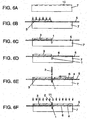
- the following steps shown in Figs. 6E and 6F are the same manufacturing method as those shown in Fig. 3.
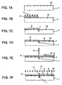
- FIG. 7A- 7F A manufacturing method for the case when optical path 5 is the optical waveguide is shown in Figs. 7A- 7F. Steps shown in Figs. 7A to 7F are the same as those shown in Fig. 6 except that optical waveguide 12 is used instead of optical fiber 5, and thus their description is omitted here.
- a manufacturing method shown in Fig. 8A to 8G is described.
- Precise V-groove 10 is created on the surface of flat substrate 7 in a first step shown in Fig. 8A.
- Flat substrate 7 is preferably made of a material having a linear expansion coefficient equivalent to that of optical fiber 5 which is mounted and fixed in a later step.
- optical fiber 5 is mounted and fixed on flat substrate 7, and cover 3 is attached, as shown in Fig. 8B.
- a mounted portion of optical fiber 5 is preferably the Clad portion where the covering is removed in order to secure the mounting accuracy.
- the angle and depth of V-groove 10 are set such that optical fiber 5 when mounted and fixed protrudes from the surface of flat substrate 7. This facilitates positioning of cover 3 by using protruding optical fiber 5 as a guide rail.
- the use of an expanded Core fiber as optical fiber 5 enlarges the spot size on the end face of optical fiber 5, reducing transmission loss and coupling loss between optical fibers 5.
- cover 3 can be fixed by irradiating typically UV ray or applying heat from one or both sides of cover 3 and flat substrate 7 so as to cure the adhesive.
- photocurable optical adhesive is used, and the light is irradiated so as to cure the adhesive. It is preferable to choose a material with optical transparency for flat substrate 7 and cover 3, taking into account the use of photocurable adhesive for fixing.
- filter insertion groove 1 is created on the surface of flat substrate 7, where optical fiber 5 is mounted and fixed, in a way such that filter insertion groove 1 crosses optical fiber 5. If the expanded Core fiber is used for optical fiber 5, filter insertion groove 1 is created such that groove 1 crosses the maximum core portion of the expanded Core.
- Filter insertion groove 1 is, for example, ground using a grinder which employs c-BN (cubic boron nitride) or diamond formed into a groove shape as abrasive grains. Alternatively, powder processing, such as using blast, is also applicable. If silicone is used as a material for the flat substrate, a groove can also be created by wet etching or dry etching.
- a grinder is more advantageous since it offers more flexibility in shape for processing the cross sectional face of filter insertion groove 1 into an irregular shape.
- Optical fiber 5 can be cut at the same time while forming filter insertion groove 1.
- abrasive grain is preferably as small as possible, if machining is chosen for creating filter insertion groove 1.
- the present invention thus uses a diamond grinder for creating filter insertion groove 1.
- a mirror-like end face of optical fiber 5 is mostly achieved by selecting a diamond grinder of #3000 or finer abrasive grains.
- Filter insertion groove 1 can be created aligned with the end face of cover 3. Alternatively, a part of cover 3 can be cut as filter insertion groove1 is created. Cutting of cover 3 at the same time eliminates positioning of cover 3 and the end face of filter insertion groove 1, reducing the manufacturing time.
- optical adhesive 6 is applied to the surface of flat substrate 7, and then multilayer filter 2 is inserted.
- optical adhesive 6 is applied to fill the inside of filter insertion groove 1 formed in the previous step. Coupling loss between optical fibers can be reduced by using optical adhesive 6 having refractive index equivalent to that of the Core material of optical fiber 5.
- the present invention is made by inserting a multilayer filter into a flat substrate having an optical path, filter insertion groove, and cover, and fixing the multilayer filter with another cover. This eliminates the optical axis adjustment required in the prior art. Consequently, the structure of optical filter module and bonding method of the present invention give improved operability, and also ensure the fixing and mounting of the multilayer filter, regardless of any warpage of the multilayer filter.
Landscapes
- Physics & Mathematics (AREA)
- General Physics & Mathematics (AREA)
- Optics & Photonics (AREA)
- Optical Couplings Of Light Guides (AREA)
- Optical Filters (AREA)
- Light Guides In General And Applications Therefor (AREA)
Abstract
An optical filter module of the present invention has a flat substrate, an
optical path formed on the flat substrate; a filter insertion groove provided, crossing
the optical path, on the flat substrate; a multilayer filter inserted, dividing the optical
path, into the filter insertion groove; and a pair of covers disposed on the flat
substrate so as to sandwich the multilayer filter. The present invention enables the
omission of the process of adjustment of the optical axis, thus achieving high
operability. At the same time, the present invention ensures fixing and mounting of
the multilayer filter even if the multilayer filter is warped.
Description
The present invention relates to optical filter modules for optical
communications in which multilayer filters are integrated with an optical fiber and an
optical waveguide, and their manufacturing methods.
A conventional method of manufacturing a module in which multilayer
filters are integrated with an optical fiber and optical waveguide is described next
with reference to Fig. 9. First, optical fiber 20 is provisionally secured onto metal
housing 23, and condenser lens 21 for focusing light diffused from optical fiber 20
and multilayer filter 22 are mounted. Then, an optical signal is fed from optical
fiber 20a at the input side. The optical signal from optical fiber 20b at the output
side is measured, such as by a power meter, to adjust the optical axis and achieve the
maximum optical signal. After adjustment, condenser lens 21 and multilayer filter
22 are caulked and fixed onto metal housing 23.
Accordingly, optical axis adjustment is required at 4 points when
manufacturing the conventional module in which multilayer filter 22 is integrated
with an optical path: (1) Optical axis adjustment between input optical fiber 20a and
condenser lens 21, (2) Optical axis adjustment between condenser lens 21 and
multilayer filter 22, (3) Optical axis adjustment between multilayer filter 22 and
condenser lens 21, and (4) Optical axis adjustment between condenser lens and
output optical fiber 20b. Operability is thus poor in the prior art.
To solve the above disadvantage, an optical filter module of the present
invention has a flat substrate, an optical path formed on the flat substrate; a filter
insertion groove provided, crossing the optical path, on the flat substrate; a multilayer
filter inserted, dividing the optical path, into the filter insertion groove; and a pair of
covers disposed on the flat substrate so as to sandwich the multilayer filter. The
present invention enables the omission of the process of adjustment of the optical
axis, thus achieving high operability. At the same time, the present invention
ensures fixing and mounting of the multilayer filter even if the multilayer filter is
warped.
An optical filter module and its manufacturing method of the present
invention are described below with reference to exemplary embodiments.
The optical filter module of the present invention is detailed below with
reference to Figs. 1A to 1C and Figs. 2A to 2D.
Fig. 1A is a top view of a two-core optical filter module, Fig. 1B is its side
view, and Fig. 1C is its sectional view. Filter insertion groove 1 for multilayer filter,
multilayer filter 2, cover 3 bonded to a flat substrate, cover 4 for press-holding
multilayer filter 2, optical path 5, optical adhesive 6, and flat substrate 7 are indicated
in Figs. 1A to 1C.
For optical adhesive 6, a material which has a refractive index equivalent to
that of the material used for optical path 5 is preferable to prevent dispersion of the
light from the end face of the optical path. For example, if optical path 5 is made of
silica glass, a material which has a refractive index as close as possible to that of
silica glass, i.e., 1.45, is preferably selected as the optical adhesive. In the first
exemplary embodiment, an optical fiber is used for optical path 5. V-groove 10 is
created on flat substrate 7 to mount and fix optical fiber 5. Optical fiber 5 is
sandwiched by cover 3 and flat substrate 7, which are disposed on the top and bottom
of optical fiber 5, by providing a predetermined depth and angle for V-groove 10.
This enables the mounting of optical fiber 5 without any positional deviation.
This V-groove 10 can also be formed on cover 3 and cover 4. The center of
optical fiber 5 is positioned right on the surface of cover 3 and flat substrate 7 by
setting depth d of V-groove 10 to:
d = r/sin(α/2)
where α is the tip angle of V-groove 10 and r is the radius of the optical fiber
to be mounted. If the optical fiber with a Clad diameter of 125 µm is used as optical
path 5, the depth of V-groove 10 is processed to about 180 µm when the tip angle of
V-groove 10 is 90°. This design ensures anchoring of optical fiber 5 by
sandwiching optical fiber 5 between covers 3 or 4 and flat substrate 7.
The depth and angle of the V-groove created on covers 3 and 4 and those of
V-groove 10 created on flat substrate 7 are not necessarily equal. The optical fiber
can be securely mounted and fixed using covers 3 and 4 and flat substrate 7 by setting
the angle and depth of the V-groove created on flat substrate 7, which sandwiches the
optical fiber, to greater than the length of protrusion of the optical fiber from the
surface of flat substrate 7 when the optical fiber is mounted in V-groove 10 of flat
substrate 7. In other words, if the optical fiber protrudes from the surface of flat
substrate 7, the optical fiber is sandwiched by V-groove created on flat substrate 7
and the groove created on the covers. Filter insertion groove 1 on flat substrate 7 is
created such that it is tilted to a predetermined angle with respect to optical path 5
configured with the optical fiber. This is formed when it is necessary to prevent
reflection of the light entering from optical path 5 onto multilayer filter 2. For
example, this is formed when multilayer filter 2 is a bandpass filter or gain-flattening
filter used in optical amplifiers. In this case, tilting angle is preferably 5 to 10° for
guiding the light with wavelength of 1.48 µm through a single mode fiber (SMF);
however, the angle depends on the wavelength of the light to be guided.
Moreover, coupling loss between the optical fiber and multilayer filter 2 can
be reduced by employing an expanded Core fiber having a partially enlarged core that
confines and guides the light in the optical fiber.
In the optical fiber module of the present invention, filter insertion groove 1
is created so as to cross optical path 5, and multilayer filter 2 is inserted in this filter
insertion groove 1. This means the path for the optical fiber is divided by filter
insertion groove 1, and thus gap G of the width of filter insertion groove 1 exists
between the end faces of the optical fiber via multilayer filter 2. If spot size w of
the light is the same at the end faces of the optical fiber, power transmission
coefficient Tg of the optical electric field between end faces of the optical fiber via
gap length G is expressed by equation (1) as follows:
Tg = {1 + (λ×G/(2×p×n×w 2 ))2 }-1
where
n: Refractive index ofmultilayer filter 2; and
λ: Wavelength.
n: Refractive index of
λ: Wavelength.
Equation (1) shows that Tg is made smaller by increasing wavelength λ or
gap length G. On the other hand, Tg approaches 1 by increasing spot size w.
Accordingly, the transmission coefficient becomes greater as spot size w on the end
face of the optical fiber exposed on the wall surface of filter insertion groove 1
becomes larger, reducing transmission loss.
A range of methods is proposed for the expanded Core fiber. One typical
example is a TEC (Thermally Expanded Core) fiber. This is a special fiber in which
the core diameter is practically expanded by diffusing a doping element which
controls the refractive index of the Core, such as GeO2, some distance into the Clad
by heating that part of the Clad. The use of this fiber enables the expansion of the
spot size of the light from the fiber end face. If this expanded Core fiber is used for
the optical filter module of the present invention, filter insertion groove 1 is
processed and created so as to cross the maximum portion of the expanded Core in
optical path 5.
Various shapes can be used for filter insertion groove 1, as shown in Figs. 2B,
2C, and 2D. In any case, filter insertion groove 1 has a shape such that it is shallow
at one groove wall and deep at the other groove wall at the bottom. Fig. 2B shows
the case where the first groove wall of filter insertion groove 1 is tilted to angle 1
while the second groove wall has a predetermined angle 2 with respect to the first
groove up to the surface of the flat substrate at the bottom. Fig. 2C shows the case
where a flat portion is formed on a part of the bottom of filter insertion groove 1.
Fig. 2D shows the case where a flat portion is formed on a part of the bottom of filter
insertion groove 1, and a perpendicular portion on the top part and tapered portion
(angle 4) on the bottom part are formed at one groove wall.
These filter insertion grooves 1 are, for example, formed by a diamond
grinder whose tip is processed in advance to generate the groove shape. In other
words, the tip shape of the diamond grinder is transferred to the groove shape.
Accordingly, the groove shape after processing largely depends on the grinding
accuracy of the diamond grinder. If the grinder width is 0.1 mm or less, processing
is difficult due to the limitation of the diamond particle diameters. If the grinder
width is 0.1 mm or above, processing is relatively easy.
The reason for processing filter insertion groove 1 into an irregular shape
with tilting angle on one side wall different from the tilting angle on the other side
wall as shown in Figs. 2B to 2D is to prevent tilting of multilayer filter 2 after
insertion. In addition, if filter insertion groove 1 is created using one end face of
cover 3 mounted in advance as the reference face during the manufacturing method
described later, degradation of grinding accuracy of filter insertion groove 1 due to
meandering of the diamond grinder is preventable because the force is applied in a
way such as to press the diamond grinder for processing towards flat substrate 7
which works as the reference face. The above description refers to the case of two
optical fibers. It is apparent that the same applies to three or more fibers or fiber
arrays.
The first exemplary embodiment refers to the case where optical path 5 is the
optical fiber, but the same applies to other optical paths such as optical waveguides.
The present invention also typically refers to a bandpass filter and gain-flattening
filter used in optical amplifiers. It is apparent that the present invention is
also applicable to other modules such as wavelength multiplexers and demultiplexers.
Furthermore, the present invention refers to lamination of multiple layers of
thin dielectric films such as SiO2 or Ta2O5 on a glass or resin substrate such as
polyimide. However, the present invention is not limited to these materials.
A method of manufacturing an optical filter module of the present invention
is described next with reference to Figs. 3 and 4.
In the method of manufacturing the optical filter module of the present
invention, precise V-groove 10 is created on the surface of flat substrate 7 in a first
step shown in Fig. 3A.
Next, in a second step, optical fiber 5 is mounted and fixed on flat substrate 7
as shown in Fig. 3B. A mounted portion of optical fiber 5 is preferably the Clad
portion where a covering over the Clad is removed in order to secure the mounting
accuracy. The angle and depth of V-groove 10 are set in advance such that optical
fiber 5 when mounted and fixed protrudes from the surface of flat substrate 7. This
facilitates positioning of cover 3 by using protruding optical fiber 5 as a guide rail.
In addition, the use of an expanded Core fiber as optical fiber 5 enlarges the
spot size on the end face of optical fiber 5, reducing transmission loss and coupling
loss between optical fibers 5.
In a third step, as shown in Fig. 3C, film insertion groove 1 is created on the
surface of flat substrate 7, on which optical fiber 5 is mounted and fixed, in a way
such that filter insertion groove 1 crosses optical fiber 5. If the expanded Core fiber
is used for optical fiber 5, filter insertion groove 1 is created such that groove 1
crosses the maximum portion of the expanded Core. Filter insertion groove 1 is, for
example, ground using a grinder which employs c-BN (cubic boron nitride) or
diamond formed into a groove shape as abrasive grains. Alternatively, powder
processing, such as using blast, is also applicable. If silicone is used as a material
for the flat substrate, a groove can also be created by wet etching or dry etching.
As described in the first exemplary embodiment, the use of a grinder is more
advantageous since it offers more flexibility in shape for processing the section face
of filter insertion groove 1 into an irregular shape. Moreover, since the formation of
film insertion groove 1 and division of optical fiber 5 are implemented
simultaneously, abrasive grain for machining should be preferably as small as
possible for improving the surface roughness of the end face of cut and divided
optical fiber 5. The present invention thus uses a diamond grinder for creating filter
insertion groove 1. A mirror-like end face of optical fiber 5 is mostly achieved by
selecting a diamond grinder of #3000 or finer abrasive grains.
In the above step, optical fiber 5 is cut and filter insertion groove 1 is created
at the same time after mounting and fixing optical fiber 5 on flat substrate 7,
eliminating the optical axis adjustment between the optical fiber for input light and
optical fiber for output light. The manufacturing time can thus be reduced.
Moreover, if the reflection of the light on the surface of multilayer filter 2
needs to be prevented in the case that multilayer filter 2 is a bandpass filter or gain-flattening
filter used in an optical amplifier, optical fiber 5 and filter insertion groove
1 are formed so as to cross at a predetermined angle. Although the angle depends
on the wavelength of the light used, the crossing angle is preferably from 5 to 10°.
Next, in a fourth step, as shown in Fig. 3D, optical adhesive 6 is applied to
the entire surface of flat substrate 7, and then cover 3 is attached, aligned with the
end face of filter insertion groove 1. Here, optical adhesive 6 is applied to fill the
inside of filter insertion groove 1 formed in the previous step. Coupling loss
between fibers can be reduced by using adhesive having refractive index equivalent
to that of the Core material of optical fiber 5.
Next, in a fifth step, as shown in Fig. 3E, multilayer filter 2 is inserted into
filter insertion groove 1 containing optical adhesive 6. Here, one end face of cover
3 is mounted aligned to a side face of filter insertion groove 1 so that multilayer filter
2 to be inserted can be mounted and fixed in alignment with one side face of filter
insertion groove 1. The size of multilayer filter 2 is set such that the top part of
inserted multilayer filter 2 always protrudes from the surface of flat substrate 7. The
protruding length of multilayer filter 2 is preferably at least half or more of the
thickness of cover 3. It is even more preferable that the protruding length is longer
than the thickness of cover 3. In Fig. 3, the protruding length of multilayer filter 2
is more than the thickness of cover 3. The top part of multilayer filter 2 thus
protrudes from the surface of cover 3.
Next, in a sixth step, as shown in Fig. 3F, cover 4 is moved from the opposite
side of cover 3 toward multilayer filter 2 to sandwich multilayer filter 2 inserted into
filter insertion groove 1. If one face of multilayer filter 2 is aligned to the side face
of cover 3 and filter insertion groove 1, cracking of multilayer filter 2 is preventable
when multilayer filter 2 is sandwiched and fixed by the other cover 4. Since
multilayer filter 2 is sandwiched by the protruding portion, warpage is correctable by
making the protruding length longer and broadening the area to be sandwiched by
covers 3 and 4, if multilayer filter 2 is warped. In addition, the use of glass as a
substrate of multilayer filter 2 is effective in preventing cracking due to stress, since
glass has a large elastic modulus. AV-groove can also be formed on the surfaces of
covers 3 and 4. The angle and depth of these V-grooves are determined as required
based on the protruding length of multilayer filter 2. If the V-groove is created on
the surface of covers 3 and 4, attachment of covers 3 and 4 using optical fiber 5 as a
guide rail is facilitated.
Lastly, in a seventh step, as shown in Fig. 3G, UV ray 11 is irradiated from
one or both sides of covers 3 and 4 and flat substrate 7 to cure optical adhesive 6,
completing the optical filter module. The use of light is effective for reducing the
manufacturing time, and thus an optical adhesive suitable for the purpose is used.
As for the optical adhesive, acrylic resin or epoxy resin of UV-curing type is
applicable. However, the present invention is not limited to photocurable adhesive.
Thermosetting adhesive is also applicable.
As for covers 3 and 4 and flat substrate 7, a material which has the same
linear expansion coefficient as that of optical fiber 5, which is mounted and fixed in
the later step, is preferable. It is also preferable to choose a material with optical
transparency, taking into account the use of photocurable adhesive for fixing covers 3
and 4 and flat substrate 7.
The above description refers to an example of using optical fiber for optical
path 5. The same applies to other optical paths such as optical waveguides. A
manufacturing method for the case when optical path 5 is the optical waveguide is
shown in Fig. 4.
Steps shown in Fig. 3 use an optical fiber for optical path 5, whereas steps
shown in Figs. 4A to 4F use an optical waveguide directly created on flat substrate 7
for optical path 5. The optical waveguide is manufactured using conventional
methods.
Since filter insertion groove 1 is created at the same time as dividing optical
waveguide 12, the need to adjust the optical axis of the optical waveguide for input
light and the optical waveguide for output light can be eliminated. Moreover, the
manufacturing time can be reduced, because the formation of filter insertion groove 1
and division of optical waveguide 12 are executed simultaneously.
In Figs. 3 and 4, multilayer filter 2 refers to a bandpass filter or gain-flattening
filter used in an optical amplifier. The present invention is also applicable
to various optical filters.
A method of manufacturing an optical filter module in a third exemplary
embodiment of the present invention is described next with reference to Figs 5 to 8.
In the method of manufacturing an optical filter module of the present
invention, precise V-groove 10 is created on the surface of flat substrate 7 in a first
step, as shown in Fig. 5A. Flat substrate 7 is preferably made of a material having a
linear expansion coefficient equivalent to that of optical fiber 5 which is mounted and
fixed in a later step.
Next, in a second step, as shown in Fig. 5B, filter insertion groove 1 is
created, and optical fiber 5 is mounted and secured onto precise V-groove 10 created
on the surface of flat substrate 7. Instead, optical fiber 5 can be mounted first and
then filter insertion groove 1 is formed. Alternatively, optical fiber 5 can be cut
while forming filter insertion groove 1. Mirror processing of a cut section of optical
fiber 5 is effective for reducing the coupling loss between optical fibers 5. If the cut
section is left as it is for use, cutting conditions need to be carefully considered. If
optical fiber 5 is cut using a diamond grinder, it is necessary to select a grinder with
small abrasive grain to make the cut end face of optical fiber 5 close to a mirror-like
finish. The present invention uses a diamond grinder for creating filter insertion
groove 1. A diamond grinder of #3000 or finer abrasive grains is chosen for
achieving an approximately mirror-like end face of optical fiber 5. A mounted and
fixed portion of optical fiber 5 is preferably the Clad portion where the covering,
such as resin coating is removed in order to secure the mounting accuracy.
The use of an expanded Core fiber as optical fiber 5 enlarges the spot size on
the end face of optical fiber 5, reducing transmission loss and coupling loss between
optical fibers 5.
Next, in a third step, as shown in Fig. 5C, optical adhesive 6 is applied to the
entire surface of flat substrate 7, and then cover 3 is attached, aligned with the end
face of filter insertion groove 1. Here, optical adhesive 6 is applied to fill the inside
of filter insertion groove 1 formed in the previous step. Coupling loss between
fibers can be reduced by using optical adhesive 6 having refractive index equivalent
to that of the Core material of optical fiber 5 to be used. A V-groove can also be
created on cover 3. The angle and depth of V-groove 10 are set such that optical
fiber 5 when mounted and fixed protrudes from the surface of flat substrate 7. This
facilitates positioning of cover 3 by using protruding optical fiber 5 as a guide rail.
If the side face of cover 3 is aligned to the side face of filter insertion groove 1,
multilayer filter 2 inserted in a next step can be mounted and fixed by aligning
multilayer filter 2 to one side face of filter insertion groove 1. It is advantageous for
preventing cracking of multilayer filter 2 when multilayer filter 2 is fixed by the other
cover 4.
Next, in a fourth step, as shown in Fig. 5D, multilayer filter 2 is inserted into
filter insertion groove 1 containing optical adhesive 6. The size of multilayer filter
2 is set such that the top part of inserted multilayer filter 2 always protrudes from the
surface of flat substrate 7. The protruding length of multilayer filter 2 is preferably
at least half or more of the thickness of cover 3. It is even more preferable that the
protruding length is longer than the thickness of cover 3. In Fig. 3, the top part of
multilayer filter 2 protrudes from the surface of flat substrate 7 by more than the
thickness of cover 3. The top part of multilayer filter 2 thus protrudes from the
surface of cover 3.
In a fifth step, as shown in Fig. 5E, optical fiber 5 is provided aligned to
precise V-groove 10 created on the surface of flat substrate 7 as a guide rail. This
enables the contact of the end face of optical fiber 5 to the surface of inserted
multilayer filter 2, further reducing transmission loss and coupling loss between
optical fibers 5.
In a sixth step, as shown in Fig. 5F, cover 4 is moved from the other side of
cover 3, and fixed, being pressed against multilayer filter 2 inserted in filter insertion
groove 1. Cover 4 is pressed and fixed at a protruding portion of multilayer filter 2.
If multilayer filter 2 is warped, the warpage is correctable by increasing the
protruding length so as to expand the area to sandwich with covers 3 and 4. The use
of glass as the substrate of the multilayer filter 2 is effective for preventing cracking
caused by stress since glass has a large elastic modulus. A V-groove can also be
formed on covers 3 and 4. In this case, the angle and depth of the V-groove are set
as required based on the protruding length of optical fiber 5.
Lastly, in a seventh step, as shown in Fig. 5G, light such as UV ray is
irradiated or heat is applied from one or both sides of covers 3 and 4 and flat
substrate 7 for curing the adhesive to complete the multilayer filter module. It is
preferable to choose a material with optical transparency for flat substrate 7 and
covers 3 and 4, taking into account the use of photocurable adhesive for fixing covers
3 and 4 and flat substrate 7.
As described above in the manufacturing method of the present invention,
cover 3 in which optical fiber 5 is mounted is prepared in advance. This eliminates
the need for providing separate steps of applying optical adhesive 6, inserting
multilayer filter 2, and fixing multilayer filter 2 by cover 3. Manufacturing control
is thus facilitated.
Next, in a manufacturing method shown in Fig. 6, a precise V-groove 10 is
created on the surface of flat substrate 7 in a first step, as shown in Fig. 6A. Flat
substrate 7 is preferably made of a material that has a linear expansion coefficient
equivalent to that of optical fiber 5 mounted and fixed in a later step.
Next, in a second step, optical fiber 5 is mounted and fixed on flat substrate 7,
and cover 3 is attached, as shown in Fig. 6B. A mounted portion of optical fiber 5 is
preferably the Clad portion where the covering is removed in order to secure the
mounting accuracy. The angle and depth of V-groove 10 are set such that optical
fiber 5 when mounted and fixed protrudes from the surface of flat substrate 7. This
facilitates positioning of cover 3 by using protruding optical fiber 5 as a guide rail.
The use of an expanded Core fiber as optical fiber 5 enlarges the spot size on the end
face of optical fiber 5, reducing transmission loss and coupling loss between optical
fibers 5. When optical adhesive is used, cover 3 can also be fixed by irradiating
typically UV ray or applying heat from one or both sides of cover 3 and flat substrate
7 so as to cure the adhesive. In this exemplary embodiment, photocurable optical
adhesive is used, and the light is irradiated so as to cure the adhesive. It is
preferable to choose a material with optical transparency for flat substrate 7 and
cover 3, taking into account the use of photocurable adhesive for fixing.
In a third step, as shown in Fig. 6C, filter insertion groove 1 is created on the
surface of flat substrate 7, where optical fiber 5 is mounted and fixed, in a way such
that filter insertion groove 1 crosses optical fiber 5. If the expanded Core fiber is
used for optical fiber 5, filter insertion groove 1 is created such that groove 1 crosses
the maximum core portion of the expanded Core. Filter insertion groove 1 is, for
example, ground using a grinder which employs c-BN (cubic boron nitride) or
diamond formed into a groove shape as abrasive grains. Alternatively, powder
processing, such as using blast, is also applicable. If silicone is used as a material
for the flat substrate, a groove can also be created by wet etching or dry etching.
As described in the first exemplary embodiment, the use of a grinder is more
advantageous since it offers more flexibility in shape for processing the section face
of filter insertion groove 1 into an irregular shape. Moreover, since the formation of
filter insertion groove 1 and division of optical fiber 5 are implemented
simultaneously, abrasive grain used for machining is preferably as small as possible
for improving the surface roughness of the end face of cut and divided optical fiber 5.
The present invention thus uses a diamond grinder for creating filter insertion groove
1. A mirror-like end face of optical fiber 5 is mostly achieved by selecting a
diamond grinder of #3000 or finer abrasive grains. Filter insertion groove 1 can be
created aligned with the end face of cover 3. Alternatively, a part of cover 3 can be
cut as filter insertion groove 1 is created.
In the above step, optical fiber 5 is cut and film insertion groove 1 is created
at the same time after mounting and fixing optical fiber 5 on flat substrate 7. This
eliminates the optical axis adjustment between the optical fiber for input light and
optical fiber for output light, and also reduces the manufacturing time. If cover 3 is
cut simultaneously, positioning of cover 3 and end face of filter insertion groove 1 is
also eliminated, allowing further reduction of the time.
Next, in a fourth step, as shown in Fig. 6D, optical adhesive 6 is applied to
the entire surface of flat substrate 7. Here, optical adhesive 6 is applied to fill the
inside of filter insertion groove 1 formed in the previous step. Coupling loss
between fibers can be reduced by using optical adhesive 6 having refractive index
equivalent to that of the Core material of optical fiber 5. The following steps shown
in Figs. 6E and 6F are the same manufacturing method as those shown in Fig. 3.
The above description refers to an example of using optical fiber for optical
path 5. The same applies to other optical paths such as optical waveguides. A
manufacturing method for the case when optical path 5 is the optical waveguide is
shown in Figs. 7A- 7F. Steps shown in Figs. 7A to 7F are the same as those shown
in Fig. 6 except that optical waveguide 12 is used instead of optical fiber 5, and thus
their description is omitted here.
Next, a manufacturing method shown in Fig. 8A to 8G is described. Precise
V-groove 10 is created on the surface of flat substrate 7 in a first step shown in Fig.
8A. Flat substrate 7 is preferably made of a material having a linear expansion
coefficient equivalent to that of optical fiber 5 which is mounted and fixed in a later
step.
In a second step, optical fiber 5 is mounted and fixed on flat substrate 7, and
cover 3 is attached, as shown in Fig. 8B. A mounted portion of optical fiber 5 is
preferably the Clad portion where the covering is removed in order to secure the
mounting accuracy. The angle and depth of V-groove 10 are set such that optical
fiber 5 when mounted and fixed protrudes from the surface of flat substrate 7. This
facilitates positioning of cover 3 by using protruding optical fiber 5 as a guide rail.
In addition, the use of an expanded Core fiber as optical fiber 5 enlarges the spot size
on the end face of optical fiber 5, reducing transmission loss and coupling loss
between optical fibers 5. When optical adhesive is used, cover 3 can be fixed by
irradiating typically UV ray or applying heat from one or both sides of cover 3 and
flat substrate 7 so as to cure the adhesive. In this exemplary embodiment,
photocurable optical adhesive is used, and the light is irradiated so as to cure the
adhesive. It is preferable to choose a material with optical transparency for flat
substrate 7 and cover 3, taking into account the use of photocurable adhesive for
fixing.
In a third step, as shown in Fig. 8C, filter insertion groove 1 is created on the
surface of flat substrate 7, where optical fiber 5 is mounted and fixed, in a way such
that filter insertion groove 1 crosses optical fiber 5. If the expanded Core fiber is
used for optical fiber 5, filter insertion groove 1 is created such that groove 1 crosses
the maximum core portion of the expanded Core. Filter insertion groove 1 is, for
example, ground using a grinder which employs c-BN (cubic boron nitride) or
diamond formed into a groove shape as abrasive grains. Alternatively, powder
processing, such as using blast, is also applicable. If silicone is used as a material
for the flat substrate, a groove can also be created by wet etching or dry etching.
As described in the first exemplary embodiment, the use of a grinder is more
advantageous since it offers more flexibility in shape for processing the cross
sectional face of filter insertion groove 1 into an irregular shape. Optical fiber 5 can
be cut at the same time while forming filter insertion groove 1. When optical fiber
5 is cut simultaneously, positioning of the end face of optical fiber 5 and filter
insertion groove 1 is eliminated, reducing the manufacturing time. To improve the
surface roughness of the end face of cut optical fiber 5, abrasive grain is preferably as
small as possible, if machining is chosen for creating filter insertion groove 1. The
present invention thus uses a diamond grinder for creating filter insertion groove 1.
A mirror-like end face of optical fiber 5 is mostly achieved by selecting a diamond
grinder of #3000 or finer abrasive grains. Filter insertion groove 1 can be created
aligned with the end face of cover 3. Alternatively, a part of cover 3 can be cut as
filter insertion groove1 is created. Cutting of cover 3 at the same time eliminates
positioning of cover 3 and the end face of filter insertion groove 1, reducing the
manufacturing time.
Next, in a fourth step, as shown in Fig. 8D, optical adhesive 6 is applied to
the surface of flat substrate 7, and then multilayer filter 2 is inserted. Here, optical
adhesive 6 is applied to fill the inside of filter insertion groove 1 formed in the
previous step. Coupling loss between optical fibers can be reduced by using optical
adhesive 6 having refractive index equivalent to that of the Core material of optical
fiber 5.
Subsequent steps shown in Figs. 8E to 8G are the same as those in the
manufacturing method shown in Fig. 5.
As described above, the present invention is made by inserting a multilayer
filter into a flat substrate having an optical path, filter insertion groove, and cover,
and fixing the multilayer filter with another cover. This eliminates the optical axis
adjustment required in the prior art. Consequently, the structure of optical filter
module and bonding method of the present invention give improved operability, and
also ensure the fixing and mounting of the multilayer filter, regardless of any
warpage of the multilayer filter.
Claims (14)
- An optical filter module comprising:a flat substrate;an optical path formed on said flat substrate;a filter insertion groove provided on said flat substrate, said filter insertion groove crossing said optical path;a multilayer filter inserted into said filter insertion groove, said multilayer filter dividing said optical path; anda pair of covers disposed on said flat substrate, said covers sandwiching said multilayer filter.
- The optical filter module as defined in Claim 1, wherein at least one of said pair of covers has an end face which is approximately flush with a wall of said filter insertion groove.
- The optical filter module as defined in Claim 1, wherein said pair of covers have at least one end face intimately contacting one face of said multilayer filter.
- The optical filter module as defined in Claim 1, wherein said filter insertion groove has a first wall and second wall facing a side face of said multilayer filter, and an angle formed by said first wall and said side face of multilayer filter is smaller than an angle formed by said second wall and said side face of multilayer filter at a position where a bottom of said multilayer filter contacts said filter insertion groove.
- The optical filter module as defined in Claim 1, wherein said optical path is an optical fiber, said optical fiber being housed in a groove created on said flat substrate.
- The optical filter module as defined in Claim 5, wherein said optical fiber has an expanded Core.
- The optical filter module as defined in Claim 6, wherein an end face of divided optical fiber is the expanded Core.
- The optical filter module as defined in Claim 5, wherein a depth of the groove housing said optical fiber is smaller than a diameter of said optical fiber, and said pair of covers have a groove at a position contacting said optical fiber.
- A method of manufacturing an optical filter module, said optical filter module comprising:a flat substrate on whose surface an optical path is created;a multilayer filter crossing said optical path; anda pair of covers sandwiching said multilayer filter and covering said surface of the flat substrate; andsaid method comprising:forming the optical path on the flat substrate;creating a filter insertion groove on said flat substrate, said filter insertion groove crossing said optical path;aligning one of walls of said filter insertion groove and an end face of a first cover;inserting a multilayer filter into said filter insertion groove; andfixing said inserted multilayer filter by press-holding said multilayer filter with a second cover.
- The method of manufacturing an optical filter module as defined in Claim 9, wherein:said optical path is an optical fiber;said step of forming the optical path comprises:creating a V-groove on said flat substrate; andhousing the optical fiber in said V-groove; andsaid step of aligning comprises:fixing said first cover on said flat substrate; and thencreating said insertion groove along an end face of said first cover, dividing said optical fiber.
- The method of manufacturing an optical filter module as defined in Claim 10, wherein said optical fiber has an expanded Core, and said expanded Core is divided in said step of aligning.
- The method of manufacturing an optical filter module as defined in Claim 9, wherein said first cover and said second cover are fixed by bonding using optical adhesive.
- The method of manufacturing an optical filter module as defined in Claim 12, wherein said optical adhesive is photocurable adhesive.
- The method of manufacturing an optical filter module as defined in Claim 10, wherein said pair of covers have a groove on a portion contacting said optical fiber, and said groove on the cover is used as a guiding groove for sliding and fixing said cover on said flat substrate.
Applications Claiming Priority (3)
| Application Number | Priority Date | Filing Date | Title |
|---|---|---|---|
| JP2001308311A JP2003114336A (en) | 2001-10-04 | 2001-10-04 | Optical filter module and method of manufacturing the same |
| JP2001308311 | 2001-10-04 | ||
| PCT/JP2002/010263 WO2003032031A1 (en) | 2001-10-04 | 2002-10-02 | Optical filter module, and manufacturing method thereof |
Publications (2)
| Publication Number | Publication Date |
|---|---|
| EP1435531A1 true EP1435531A1 (en) | 2004-07-07 |
| EP1435531A4 EP1435531A4 (en) | 2006-04-19 |
Family
ID=19127644
Family Applications (1)
| Application Number | Title | Priority Date | Filing Date |
|---|---|---|---|
| EP02800732A Withdrawn EP1435531A4 (en) | 2001-10-04 | 2002-10-02 | OPTICAL FILTER MODULE AND MANUFACTURING METHOD THEREFOR |
Country Status (6)
| Country | Link |
|---|---|
| US (1) | US7039279B2 (en) |
| EP (1) | EP1435531A4 (en) |
| JP (1) | JP2003114336A (en) |
| CN (1) | CN1206547C (en) |
| TW (1) | TWI255927B (en) |
| WO (1) | WO2003032031A1 (en) |
Families Citing this family (2)
| Publication number | Priority date | Publication date | Assignee | Title |
|---|---|---|---|---|
| JP4682111B2 (en) * | 2006-09-14 | 2011-05-11 | 富士通株式会社 | Waveguide type optical device and manufacturing method thereof |
| EP4049074A4 (en) | 2019-10-25 | 2023-11-15 | CommScope Technologies LLC | Integrated optical wavelength division multiplexing devices |
Family Cites Families (21)
| Publication number | Priority date | Publication date | Assignee | Title |
|---|---|---|---|---|
| JPS6434604A (en) | 1987-07-24 | 1989-02-06 | Kobe Steel Ltd | Tool exchanger for shearing machine |
| JPS6434604U (en) * | 1987-08-25 | 1989-03-02 | ||
| JP2730901B2 (en) * | 1988-02-20 | 1998-03-25 | 富士通株式会社 | Optical function device |
| JPH0284601A (en) * | 1988-06-29 | 1990-03-26 | Furukawa Electric Co Ltd:The | Optical parts and its production |
| JPH02284103A (en) * | 1989-04-26 | 1990-11-21 | Furukawa Electric Co Ltd:The | Optical parts and production thereof |
| JPH0611622A (en) * | 1992-06-24 | 1994-01-21 | Sumitomo Electric Ind Ltd | Optical fiber type demultiplexer / multiplexer |
| JPH0634837A (en) * | 1992-07-15 | 1994-02-10 | Sumitomo Electric Ind Ltd | Optical component |
| JPH075346A (en) * | 1993-06-18 | 1995-01-10 | Sumitomo Osaka Cement Co Ltd | Optical fiber fixing means for optical element and method for connecting and fixing optical fiber to optical element |
| CA2120792C (en) * | 1993-07-16 | 2006-05-09 | Eisuke Sasaoka | Optical waveguide device |
| JPH07281049A (en) * | 1994-04-11 | 1995-10-27 | Fuji Elelctrochem Co Ltd | Method for manufacturing fiber integrated optical component |
| JPH08184712A (en) * | 1995-01-06 | 1996-07-16 | Furukawa Electric Co Ltd:The | Optical fiber type optical filter |
| JPH08211228A (en) * | 1995-02-06 | 1996-08-20 | Furukawa Electric Co Ltd:The | Filtered optical fiber |
| JP3500765B2 (en) * | 1995-04-25 | 2004-02-23 | 住友電気工業株式会社 | Optical filter manufacturing method |
| JP3175814B2 (en) | 1995-10-09 | 2001-06-11 | 日本電信電話株式会社 | Waveguide optical device and method of manufacturing the same |
| JPH1048439A (en) | 1996-08-02 | 1998-02-20 | Japan Aviation Electron Ind Ltd | Optical filter |
| JPH10133041A (en) * | 1996-10-29 | 1998-05-22 | Hitachi Cable Ltd | Waveguide with filter |
| JPH10307221A (en) | 1997-05-09 | 1998-11-17 | Hitachi Ltd | Semiconductor optical coupling device and assembling method thereof |
| JP3708306B2 (en) * | 1997-10-06 | 2005-10-19 | 富士通株式会社 | Wavelength division multiplexing optical device and manufacturing method thereof |
| US6314228B1 (en) * | 1998-02-02 | 2001-11-06 | Matsushita Electric Industrial Co., Ltd. | Optical waveguide component and a method of producing the same |
| JP3792040B2 (en) * | 1998-03-06 | 2006-06-28 | 松下電器産業株式会社 | Bidirectional optical semiconductor device |
| JP3749652B2 (en) * | 2000-06-19 | 2006-03-01 | 株式会社日立製作所 | Optical multiplexer / demultiplexer, optical waveguide module, and optical communication device |
-
2001
- 2001-10-04 JP JP2001308311A patent/JP2003114336A/en active Pending
-
2002
- 2002-10-02 EP EP02800732A patent/EP1435531A4/en not_active Withdrawn
- 2002-10-02 WO PCT/JP2002/010263 patent/WO2003032031A1/en not_active Ceased
- 2002-10-02 CN CNB028031024A patent/CN1206547C/en not_active Expired - Fee Related
- 2002-10-02 TW TW091122721A patent/TWI255927B/en not_active IP Right Cessation
- 2002-10-02 US US10/471,419 patent/US7039279B2/en not_active Expired - Fee Related
Also Published As
| Publication number | Publication date |
|---|---|
| TWI255927B (en) | 2006-06-01 |
| JP2003114336A (en) | 2003-04-18 |
| US7039279B2 (en) | 2006-05-02 |
| CN1206547C (en) | 2005-06-15 |
| US20040120650A1 (en) | 2004-06-24 |
| EP1435531A4 (en) | 2006-04-19 |
| CN1476540A (en) | 2004-02-18 |
| WO2003032031A1 (en) | 2003-04-17 |
Similar Documents
| Publication | Publication Date | Title |
|---|---|---|
| US5481629A (en) | Hybrid optical IC with optical axes at different levels | |
| US4958897A (en) | Thin film optical component for use in optical transmission lines and method of manufacturing the same | |
| US7123798B2 (en) | Optical device and method of producing the same | |
| KR20080108414A (en) | Wideband Optical Coupling into Thin SOI COMOS Optical Integrated Circuits | |
| US20040184705A1 (en) | Optical waveguide component and method of manufacturing the same | |
| EP0926520A2 (en) | Optical fiber array | |
| US7172344B2 (en) | Optical filter module and manufacturing method thereof | |
| US7065269B2 (en) | Optical multiplexer/demultiplexer, optical integrated circuit and light transceiver using the same | |
| US7039279B2 (en) | Optical filter module and manufacturing method thereof | |
| US7729580B2 (en) | Waveguide type optical device and manufacturing method of the waveguide type optical device | |
| US7044649B2 (en) | Optical filter module, and manufacturing method thereof | |
| US7394955B2 (en) | Optical component and method of manufacturing the same | |
| JP2007183467A (en) | Optical waveguide with mirror and manufacturing method thereof | |
| JP2004233982A (en) | Optical waveguide component and method of manufacturing the same | |
| US7634166B2 (en) | Marker groove forming device | |
| JP4140094B2 (en) | Optical waveguide device and manufacturing method thereof | |
| JP2004004349A (en) | Optical mounting substrate, optical device, and optical device manufacturing method | |
| WO2021106163A1 (en) | Optical fiber array | |
| GB2374156A (en) | Aligning array of optical fibres with waveguides of optical device | |
| WO2004011982A1 (en) | Optical device and production method therefor | |
| JP2002318322A (en) | Optical waveguide component and method of manufacturing the same |
Legal Events
| Date | Code | Title | Description |
|---|---|---|---|
| PUAI | Public reference made under article 153(3) epc to a published international application that has entered the european phase |
Free format text: ORIGINAL CODE: 0009012 |
|
| 17P | Request for examination filed |
Effective date: 20030930 |
|
| AK | Designated contracting states |
Kind code of ref document: A1 Designated state(s): AT BE BG CH CY CZ DE DK EE ES FI FR GB GR IE IT LI LU MC NL PT SE SK TR |
|
| AX | Request for extension of the european patent |
Extension state: AL LT LV MK RO SI |
|
| A4 | Supplementary search report drawn up and despatched |
Effective date: 20060302 |
|
| RAP1 | Party data changed (applicant data changed or rights of an application transferred) |
Owner name: PANASONIC CORPORATION |
|
| STAA | Information on the status of an ep patent application or granted ep patent |
Free format text: STATUS: THE APPLICATION IS DEEMED TO BE WITHDRAWN |
|
| 18D | Application deemed to be withdrawn |
Effective date: 20090501 |