EP1435456A2 - Hydraulic Pump - Google Patents
Hydraulic Pump Download PDFInfo
- Publication number
- EP1435456A2 EP1435456A2 EP03257660A EP03257660A EP1435456A2 EP 1435456 A2 EP1435456 A2 EP 1435456A2 EP 03257660 A EP03257660 A EP 03257660A EP 03257660 A EP03257660 A EP 03257660A EP 1435456 A2 EP1435456 A2 EP 1435456A2
- Authority
- EP
- European Patent Office
- Prior art keywords
- plunger
- delivery
- pump
- hydraulic pump
- filling
- Prior art date
- Legal status (The legal status is an assumption and is not a legal conclusion. Google has not performed a legal analysis and makes no representation as to the accuracy of the status listed.)
- Granted
Links
Images
Classifications
-
- F—MECHANICAL ENGINEERING; LIGHTING; HEATING; WEAPONS; BLASTING
- F04—POSITIVE - DISPLACEMENT MACHINES FOR LIQUIDS; PUMPS FOR LIQUIDS OR ELASTIC FLUIDS
- F04B—POSITIVE-DISPLACEMENT MACHINES FOR LIQUIDS; PUMPS
- F04B1/00—Multi-cylinder machines or pumps characterised by number or arrangement of cylinders
- F04B1/04—Multi-cylinder machines or pumps characterised by number or arrangement of cylinders having cylinders in star- or fan-arrangement
- F04B1/0404—Details or component parts
- F04B1/0408—Pistons
-
- F—MECHANICAL ENGINEERING; LIGHTING; HEATING; WEAPONS; BLASTING
- F04—POSITIVE - DISPLACEMENT MACHINES FOR LIQUIDS; PUMPS FOR LIQUIDS OR ELASTIC FLUIDS
- F04B—POSITIVE-DISPLACEMENT MACHINES FOR LIQUIDS; PUMPS
- F04B1/00—Multi-cylinder machines or pumps characterised by number or arrangement of cylinders
- F04B1/04—Multi-cylinder machines or pumps characterised by number or arrangement of cylinders having cylinders in star- or fan-arrangement
- F04B1/06—Control
-
- F—MECHANICAL ENGINEERING; LIGHTING; HEATING; WEAPONS; BLASTING
- F04—POSITIVE - DISPLACEMENT MACHINES FOR LIQUIDS; PUMPS FOR LIQUIDS OR ELASTIC FLUIDS
- F04B—POSITIVE-DISPLACEMENT MACHINES FOR LIQUIDS; PUMPS
- F04B49/00—Control, e.g. of pump delivery, or pump pressure of, or safety measures for, machines, pumps, or pumping installations, not otherwise provided for, or of interest apart from, groups F04B1/00 - F04B47/00
- F04B49/12—Control, e.g. of pump delivery, or pump pressure of, or safety measures for, machines, pumps, or pumping installations, not otherwise provided for, or of interest apart from, groups F04B1/00 - F04B47/00 by varying the length of stroke of the working members
- F04B49/121—Lost-motion device in the driving mechanism
-
- F—MECHANICAL ENGINEERING; LIGHTING; HEATING; WEAPONS; BLASTING
- F04—POSITIVE - DISPLACEMENT MACHINES FOR LIQUIDS; PUMPS FOR LIQUIDS OR ELASTIC FLUIDS
- F04B—POSITIVE-DISPLACEMENT MACHINES FOR LIQUIDS; PUMPS
- F04B7/00—Piston machines or pumps characterised by having positively-driven valving
- F04B7/04—Piston machines or pumps characterised by having positively-driven valving in which the valving is performed by pistons and cylinders coacting to open and close intake or outlet ports
Definitions
- the invention relates to a hydraulic pump for pressurising liquids and, in particular, to a hydraulic pump for fuel.
- the pump has particular application in fuel injection systems for supplying high pressure fuel to a compression ignition internal combustion engine, and more particularly, but not exclusively, for use in common rail fuel injection systems.
- Pumps for gases are known in which the requirement for inlet and delivery valves is avoided in a dual plunger scheme. This is achieved through cooperation of first and second pumping plungers of the pump with respective inlet and delivery ports of the pump chamber.
- One of the plungers cooperates with the inlet port to control the flow into the pump chamber, and the other plunger cooperates with the delivery port to control the flow out of the pump chamber.
- the plungers are driven approximately sinusoidally, typically by a crank shaft and connecting rods, or by means of an eccentric cam.
- Such pumps can be used to pump gases due to their compressibility, but when driven in this manner it is not possible to operate such pumps with liquids as a hydraulic lock is formed in the pump chamber for periods of the pumping cycle when both the inlet and delivery ports are closed.
- a hydraulic pump for performing a pumping cycle having a filling phase during which a liquid is supplied through an inlet port to a pump volume and a pumping phase during which liquid is supplied from the pump volume through a delivery port, the pump comprising;
- the inventor has overcome this problem with the realisation that by allowing the effective length of one of the plungers to vary throughout the pumping cycle, the pump chamber can be maintained at a substantially constant volume during the period when both ports are closed.
- the solution to this problem is achieved by providing one of the plungers with resilient means in the form of a spring that is pre-loaded to oppose liquid pressure within the pump volume, with the pre-load selected to be greater than liquid pressure within the pump volume during the filling phase but less than liquid pressure within the pump volume during the pumping phase.
- the pre-load acts to reduce the effective length of the delivery plunger during the plunger return stroke, and to maintain the plunger at its reduced effective length during an initial part of the return stroke, so as to maintain the delivery port open for a longer period of time and to maintain the volume of the pump chamber at a substantially constant value during the period for which both the delivery port and the inlet port are closed. The occurrence of a hydraulic lock is therefore avoided.
- the filling and delivery plungers are driven, in use, by a cam arrangement including first and second cams for driving a respective one of the filling and delivery plungers to perform approximate sinusoidal motion.
- the first and second cams may be of substantially identical form and may be offset angularly relative to one another around a common cam shaft.
- the filling and delivery plungers may be driven by a common cam arrangement, with the filling and delivery plungers spaced angularly around a cam of the arrangement.
- the cam arrangement may be arranged such that movement of the filling plunger relative to the delivery plunger is out of phase by between 110 and 130 degrees, and more preferably between 120 and 130 degrees.
- the filling plunger is provided with the resilient means and the filling plunger may be formed from first and second filling plunger parts with the resilient means provided between the first and second filling plunger parts.
- the delivery plunger is provided with the resilient means and the delivery plunger may be formed from first and second delivery plunger parts with the resilient means provided between the first and second delivery plunger parts.
- the resilient means has a pre-load selected to be greater than liquid pressure within the pump volume during the filling phase but less than liquid pressure within the pump volume during the pumping phase, and whereby the resilient means adopts a relaxed state when said liquid pressure is less than the pre-load and is urged into a compressed state when said liquid pressure exceeds said pre-load.
- the second plunger part includes a stop member for engagement with the first plunger part when the resilient means is in a fully compressed state.
- the pump may also include adjustment means for adjusting the extent of variation of the effective length of the plunger that is permitted, in use.
- the adjustment means may include means for adjusting the position of the stop member relative to the second plunger part.
- the adjustment means may take the form of a screw threaded arrangement which couples the stop member to the second plunger part.
- the adjustment means may include means for varying the pre-load of the resilient means.
- the adjustment means may include a shim or other intermediate piece, located between the spring and the second plunger part, whereby providing a shim of different size enables the setting of different values for the pre-load of the resilient means.
- the resilient means takes the form of a compression spring alternatively it may take the form of a rubber spring or a pneumatic or hydraulic device.
- the pump is particularly suitable for use in pumping fuel for delivery to a compression ignition internal combustion engine, and especially for delivering fuel to a common rail of a fuel injection system for such an engine.
- the hydraulic pump of the present invention provides a particular advantage when used as a fuel pump of a fuel injection system for a compression ignition engine.
- a fuel pump that is suitable for use in a common rail fuel injection system, but which provides a cost benefit over known designs by removing the need for inlet and delivery valves. It is acknowledged that pumps utilising this feature exist in the field of gas pump technology, and by way of background to the present invention one such form of gas pump of this type is described below.
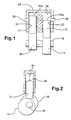
- a known form of pump for gases includes first and second plungers 10, 12 of cylindrical form that are driven, in use, by means of a respective cam 14, 16, both of which are carried by a common, engine driven cam shaft 18.
- each of the plungers 10, 12 reciprocates within a respective bore 20, 22 provided in a pump housing 24.
- the bores 20, 22 communicate with one another and define, together with end surfaces 10a, 12a of the first and second plungers respectively 10, 12, a pump volume or chamber 26 for receiving a gas.
- the pump housing is provided with first and second ports 30, 32 that define inlet and delivery ports respectively to the pump chamber 26. Gas at relatively low pressure is supplied to the pump chamber through the inlet port 30, and gas is pumped from the pump chamber 26 through the delivery port 32.
- the outer cylindrical surface of the first plunger 10 (referred to as the "filling plunger") cooperates with the inlet port 30 as the plunger 10 reciprocates within its bore 20, so as to provide a valving function for the inlet port 30.
- the filling plunger 10 occupies positions in the bore 20 for which the outer surface of the plunger 10 covers the inlet port 30, gas is unable to flow into (or out of) the pump chamber 26 through the inlet port 30.
- the surface of the filling plunger 10 uncovers the inlet port 30, a flow of gas into the pump chamber 26 is permitted.
- the outer cylindrical surface of the second plunger 12 (referred to as the "delivery plunger") cooperates with the delivery port 30 as the plunger 12 reciprocates within its bore 22, so as to provide a valving function for the delivery port 32.
- the delivery plunger 12 occupies positions in the bore 22 for which the outer surface of the plunger 12 covers the delivery port 32, gas is unable to flow out of (or in to) the pump chamber 26 through the delivery port 32.
- each plunger 10, 12 is driven under the influence of its respective cam to perform sinusoidal motion, with each plunger having a forward stroke and a return stroke.
- each plunger 10, 12 is driven inwardly within its bore 20, 22 in a direction to close the respective port 30, 32, and continued movement through the forward stroke thereafter maintains the port 30, 32 in its closed state. Whilst the plungers are performing their forward strokes, the volume of the pump chamber 26 above the associated plunger is reducing.
- each plunger 10, 12 moves outwardly from its bore 20, 22 in a direction to open the respective port 30, 32, and continued movement through the return stroke thereafter maintains the port 30, 32 in its open state.
- Each plunger 10, 12 is urged outwardly from its bore 20, 22 as a result of the force due to gas acting on the uppermost end surface of the plunger, so that the volume of the pump chamber 26 above the plunger is increasing during the plunger return strokes.
- the cams 14, 16 for the filling and delivery plungers 10, 12 respectively are of identical form, and are mounted eccentrically on the cam shaft 18 (as seen most clearly in Figure 2).
- the cams 14, 16 are angularly offset relative to each other by 120 degrees, and thus sinusoidal motion of the plungers is phased by 120 degrees.
- Figure 3 illustrates the characteristics of plunger movement throughout the pumping cycle.
- Line 40 (solid line) represents movement of the filling plunger 10 throughout the pumping cycle (i.e. for a 360 degree rotation of the cam 14), and line 42 (dashed line) represents movement of the delivery plunger 12 throughout the pumping cycle (i.e. for a 360 degree rotation of the cam 16).
- Line 44 (solid line) represents the period for which the inlet port 30 is uncovered by the filling plunger 10
- line 46 (dashed line) represents the period for which the inlet port 32 is uncovered by the delivery plunger 12.
- Line 48 (dashed-dotted line) represents an indication of the volume of the pump chamber throughout a 360 degree pumping cycle.
- the filling plunger 10 At the start of the pumping cycle (0 degrees cam rotation), the filling plunger 10 is at its outermost position within its bore 20 (referred to as "bottom dead centre") and, hence, the inlet port 30 is uncovered. Until such time as the filling plunger 10 is driven to a position in which its outer surface covers the inlet port 30 (at about 70 degrees), gas is able to flow into the pump chamber 26. During this period, between 0 and 70 degrees, the delivery plunger 12 is moving outwardly from its bore 22 (its return stroke) and the delivery port 32 is closed, so that gas is unable to escape from the pump chamber 26. Once the inlet port 30 becomes covered by the filling plunger 10, the further flow of gas into the pump chamber 26 is prevented. Eventually, the delivery plunger 12 is moved past the point at which the delivery port 32 is uncovered (about 70 degrees) and the delivery port 32 opens, thereby permitting pumped gas to escape from the chamber 26 through the port 32.
- the delivery plunger 12 At around 135 degrees of cam rotation, the delivery plunger 12 reaches the end of its return stroke (i.e. "bottom dead centre) and commences its forward stroke. The delivery plunger 12 forward stroke continues until around 315 degrees of cam rotation when it reaches its innermost position in the bore 22 (referred to as “top dead centre”). After about 200 degrees of cam rotation it can be seen that the delivery port 32 is caused to be closed by the delivery plunger 12, thereby preventing further delivery of gas through the delivery port 32.
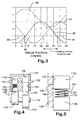
- the hydraulic pump of a first embodiment of the present invention is shown in Figure 4, and is particularly suitable for use as a high pressure pump for a fuel injection system of a compression ignition engine.
- the pump includes first and second plungers, a filling plunger 110 and a delivery plunger 112, each of which is reciprocable within a respective bore 120, 122 provided in a pump housing 124 under the influence of a respective cam 114, 116 mounted upon a common cam shaft 118, as described previously for the pump of Figure 1.
- the bores 120, 122 communicate with each other at their uppermost ends (in the orientation shown) and define, together with end surfaces of the filling and delivery plungers 110, 112, a pump chamber 126 for receiving fuel through a pump inlet port 130 provided in a wall of the pump housing 124.
- the filling plunger 110 cooperates with the inlet port 130 to provide a means for controlling fuel flow into the pump chamber 126 from a low pressure fuel supply.
- a delivery port 132 is also provided in the pump housing 124 in the region of the bore 122, and the outer surface of the delivery plunger 112 cooperates with the delivery port 132 to provide a means for controlling the delivery of pressurised fuel from the pump chamber 126 to a high pressure fuel volume.
- the low pressure fuel supply may be a low pressure pump, for example a transfer pump
- the high pressure fuel volume may be a common rail of a fuel injection system.
- the delivery plunger 112 is formed from two parts, a first upper part 112a and a second lower part 112b, between which resilient means, in the form of a compression spring 150, is located within a spring chamber 148.
- the upper part 112a of the delivery plunger 112 cooperates with the delivery port 132 to control fuel flow out of the chamber 126.
- the lower part 112b of the delivery plunger 112 is provided with an abutment piece or stop 112c, which extends part way through the spring 150 and which, at its upper end, defines a stop surface 112d that is engageable with the upper part 112a of the delivery plunger 112 during certain phases of the pumping cycle.
- the spring 150 is selected to have a pre-load that opposes fuel pressure within the pump chamber 126 and is either urged into a relaxed state (as shown in Figure 5), when the pre-load overcomes fuel pressure within the pump chamber 126 or is urged into a compressed state when fuel pressure within the pump chamber 126 overcomes the pre-load.
- a relaxed state the upper part 112a of the delivery plunger 112 is spaced away from the stop surface 112d, and when in a fully compressed state the upper part 112a of the delivery plunger 112 is engaged with the stop surface 112d.
- the effective length of the delivery plunger 112 is varied as the upper part 112a of the plunger 112 is moved (or not) under the influence of fuel pressure within the pump chamber 126. It is this variation in the effective length of the delivery plunger (i.e. the distance between the uppermost surface of the upper plunger part 112a exposed to fuel pressure within the pumping chamber, and the lower surface of the lower plunger part 112b that permits a substantially constant pump volume to be maintained during periods in the pumping cycle for which both the inlet port 130 and the delivery port 132 are covered by their respective plungers 110, 112.
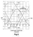
- Line 160 represents movement of the filling plunger 110, which is approximately sinusoidal, and it can be seen that movement through the filling plunger forward stroke (between 0 and 180 degrees) is symmetric with movement through the return stroke (between 180 degrees and 360 degrees).
- Line 162 represents the state of the inlet port 130, and it can be seen that between about 300 degrees of one cycle and about 65 degrees of the subsequent cycle the filling plunger 110 is at a position within its bore 120 for which the inlet port 130 is uncovered. When the inlet port 130 is in this open state, fuel is able to flow into the pump chamber 126 from the low pressure fuel supply.
- Line 170 (dashed line) represents the state of the delivery port 132 throughout the 360 degree cycle.
- Line 164 (dashed) represents movement of the delivery plunger 112 throughout a 360 degree cycle, and it can be seen that plunger movement deviates from the symmetric, sinusoidal motion of the filling plunger 110. During various stages of the cycle, movement of the delivery plunger 112 will be influenced to a differing extent by the pre-load of the spring 150.
- a first dotted line 166 is a hypothetical representation of movement of the delivery plunger 112, if it were to complete a full cycle with the spring 150 in its relaxed state.
- a second dotted line 168 is a hypothetical representation of movement of the delivery plunger 112, if it were to complete a full cycle with the spring 150 its fully compressed state.
- Actual movement of the delivery plunger 112 is illustrated by line 164, and represents the spring 150 moving between its fully compressed and relaxed conditions during the cycle. Switching of the spring 150 between its relaxed and compressed states has the effect of varying the effective length of the delivery plunger 112.
- the pre-load of the spring 150 is selected such that at commencement of the filling stroke of the filling plunger 110, and during the period for which the inlet port 130 is open (i.e. the "filling phase"), the spring 150 is relaxed and serves to urge the upper part 112a of the plunger 112 away from the stop surface 112d. With the spring in its relaxed state, the delivery plunger 112 therefore has a first, relatively long effective length. It is important that the pre-load of the spring 150 is large enough to maintain the delivery plunger 112 at its first, longer effective length during the filling phase of the cycle, so as to be sure the delivery port 132 is not open at the same time as the inlet port 130.
- the spring 150 is compressed, moving between its fully relaxed and fully compressed states, and the effective length of the delivery plunger 112 starts to change.
- the upper part 112a of the plunger 112 is engaged with the stop surface 112d and actual movement of the delivery plunger 112 (as represented by line 164) then follows line 168.
- the delivery plunger 112 continues its return stroke, until about 135 degrees when it reaches bottom dead centre, and then commences the subsequent forward stroke.
- the filling plunger 110 continues its forward stroke (beyond the position at which the inlet port 130 is closed), so that the volume of the pump chamber 126 is reduced, therefore causing fuel within the chamber to be pumped at increased pressure through the open delivery port 132.
- the delivery plunger 112 passes the point in its forward stroke at which the delivery port is closed (as represented by line 170).
- the filling plunger 110 has passed top dead centre (around 180 degrees) and is performing its return stroke, with the inlet port 130 still closed. Between about 230 and 305 degrees both the inlet port 130 and the delivery port 132 are therefore both closed.
- the force due to fuel within the pump chamber 126 acting on the upper part 112a of the delivery plunger 112 is reduced, and thus the spring 150 starts to relax.
- This causes the effective length of the delivery plunger 112 to be increased, and at a cam shaft position of about 275 degrees movement of the delivery plunger 112 follows the characteristic shown by line 166.
- the spring 150 is able to relax during the period when both the inlet and delivery ports 130, 132 are closed, and it is by this means that the volume of the pump chamber 126 maintains a substantially constant volume during this time. It is this that avoids the occurrence of a hydraulic lock, which would otherwise occur if the pump chamber volume was to change whilst both ports were closed.
- Line 172 represents the volume of the pump chamber 126 through a 360 degree rotation of the cam shaft 118, and it can be seen that for the period during which both the inlet port 130 and the delivery port 132 are closed by their respective plungers (referred to as the "dead period"), the volume of the chamber 126 remains substantially constant.
- the pump may be provided with adjustment means for enabling the variation in effective plunger length to be adjusted, prior to pump use.
- the adjustment means may include means for varying the position of the stop 112c of the delivery plunger 112 relative to the lower part 112b of the plunger 112, so as to permit the change in effective length of the delivery plunger 112, between spring-relaxed and spring-compressed states, to be adjusted. This permits application of the pump in different environments, and also permits differences in pumps of nominally identical specification to be accounted for at the installation stage.
- the adjustment feature may be provided a screw threaded arrangement, for screw threading the stop member to the lower plunger part, and by varying the extent to which the stop is screwed into the plunger part prior to installation to achieve the required variation in effective plunger length, in use.
- the adjustment means may include means for varying the pre-load of the spring 150 prior to use.
- the plunger may be provided with a shim that is located between the upper surface of the lower plunger part 112b and the base of the spring 150. Shims of different sizes enable the pre-load of the spring 150 to be set to different values, as may be required for different pump applications or different pump specifications.
- the resilient means by which the effective length of the delivery plunger 112 is varied may take a form other than a compression spring 150.
- the resilient means may be provided by a rubber spring, by pneumatic device or by means of a variable hydraulic pressure within the chamber 148 between the upper and lower parts 112a, 112b of the plunger 112, providing always that the biasing force acting against fuel pressure within the pump chamber 126, tending to increase the effective length of the delivery plunger 112, is greater than fuel pressure within the chamber 126 during the filling phase ("filling pressure") but less than pressure within the pump chamber 126 during the pumping phase (“pumping pressure").
- each plunger 110, 112 need not be driven by its own dedicated cam, but alternatively both plungers may be driven by a common cam.
- the plungers 110, 112 may be spaced angularly around the common cam by the required amount, for example 130 degrees.
- the filling plunger 110 with resilient means for varying the effective length of the filling plunger throughout the 360 degree pumping cycle. This may be achieved in a similar manner to that described for the delivery plunger 112 in the Figure 4 embodiment, by forming the filling plunger in two parts and by providing a spring or other resilient means between the two plunger parts.
- the filling plunger spring is selected to have a pre-load greater than liquid pressure within the pump volume during the filling phase (i.e. so the filling plunger has a relative long effective length) but less than liquid pressure within the pump volume during the pumping phase (i.e. so the filling plunger takes up a reduced effective length). This means that the filling plunger keeps the inlet port closed for longer during the pumping cycle, with the result that the pump volume is maintained at a substantially constant value for that period of the cycle for which both the inlet and delivery ports are closed.
- adjustment feature for enabling the variation in effective plunger length and/or for enabling the setting of different spring preloads may also be included in embodiments of the invention where it is the effective length of the filling plunger 110 that is variable.
Landscapes
- Engineering & Computer Science (AREA)
- Mechanical Engineering (AREA)
- General Engineering & Computer Science (AREA)
- Fuel-Injection Apparatus (AREA)
- Valve Device For Special Equipments (AREA)
Abstract
Description
Claims (18)
- A hydraulic pump for performing a pumping cycle having a filling phase during which a liquid is supplied through an inlet port (130) to a pump volume (126) and a pumping phase during which liquid is supplied from the pump volume through a delivery port (132), the pump comprising;and wherein one of the filling or delivery plungers (110,112) is provided with resilient means (150) that serves to oppose liquid pressure within the pump volume (126) to permit variation of the effective length of said plunger throughout the pumping cycle, and thereby to ensure the pump volume remains substantially constant during a period of the pumping cycle for which both the inlet and delivery ports (130,132) are closed.a filling plunger (110) that is cooperable with the inlet port (130) to control the supply of liquid to the pump volume (126),a delivery plunger (112) that is cooperable with the delivery port (132) to control the supply of liquid out of the pump volume (126), wherein each of the filling and delivery plungers (110,112) is driven, in use, to perform a pumping stroke and a return stroke and such that movement of one of said plungers is out of phase with movement of the other of said plungers,
- A hydraulic pump as claimed in Claim 1, whereby the filling and delivery plungers (130,132) are driven, in use, to perform sinusoidal motion and whereby movement of the plungers is out of phase by between 110 and 130 degrees.
- A hydraulic pump as claimed in Claim 2, whereby the filling and delivery plungers (110,112) are driven, in use, such that movement of the plungers is out of phase by between 120 and 130 degrees.
- A hydraulic pump as claimed in Claim 3, whereby movement of the plungers is out of phase by substantially 130 degrees.
- A hydraulic pump as claimed in any one of Claims 1 to 4, including a first cam (114) for driving the filling plunger (110) and a second cam (116) for driving the delivery plunger (112).
- A hydraulic pump as claimed in Claim 5, wherein the first and second cams (114,116) are of substantially identical form and are offset angularly relative to one another by about 130 degrees around a common cam shaft (118).
- A hydraulic pump as claimed in any one of Claims 1 to 6, wherein the filling plunger (110) is formed from first and second plunger parts and wherein the resilient means is provided between the first and second plunger parts.
- A hydraulic pump as claimed in any of Claims 1 to 6, wherein the delivery plunger (112) is formed from first and second plunger parts (112a, 112b) and wherein the resilient means (150) is provided between the first and second plunger parts.
- A hydraulic pump as claimed in Claim 7 or Claim 8, wherein the resilient means (150) has a pre-load selected to be greater than liquid pressure within the pump volume (126) during the filling phase but less than liquid pressure within the pump volume (126) during the pumping phase, and whereby the resilient means is urged into a relaxed state when said liquid pressure is less than the pre-load and into a compressed state when said liquid pressure exceeds said pre-load.
- A hydraulic pump as claimed in any one of Claims 7 to 9, further comprising adjustment means for permitting adjustment of the extent of variation of the effective length of the plunger.
- A hydraulic pump as claimed in Claim 10, wherein the second plunger part (112b) includes a stop member (112c) for engagement with the first plunger part (112a) when the resilient means (150) is in a fully compressed state.
- A hydraulic pump as claimed in Claim 11, where the adjustment means includes means for adjusting the position of the stop member (112c) relative to the second plunger part (112b).
- A hydraulic pump as claimed in Claim 12, wherein the adjustment means includes a screw threaded arrangement that couples the stop member (112c) to the second plunger part (112b).
- A hydraulic pump as claimed in any one of Claims 10 to 13, wherein the adjustment means includes means for varying the pre-load of the resilient means (150).
- A hydraulic pump as claimed in Claim 14, wherein the adjustment means includes a shim located between the resilient means (150) and the second plunger part (112b), whereby providing a shim of different size enables different preloads of the resilient means to be set.
- A hydraulic pump as claimed in any of Claims 1 to 15, wherein the resilient means takes the form of a compression spring (150).
- A hydraulic pump as claimed in any one of Claims 1 to 16, for use in pumping fuel for delivery to a compression ignition internal combustion engine.
- A hydraulic pump as claimed in Claim 17, for use in delivering fuel to a common rail of the engine.
Applications Claiming Priority (2)
| Application Number | Priority Date | Filing Date | Title |
|---|---|---|---|
| GB0228559 | 2002-12-06 | ||
| GBGB0228559.1A GB0228559D0 (en) | 2002-12-06 | 2002-12-06 | Hydraulic pump |
Publications (3)
| Publication Number | Publication Date |
|---|---|
| EP1435456A2 true EP1435456A2 (en) | 2004-07-07 |
| EP1435456A3 EP1435456A3 (en) | 2005-05-11 |
| EP1435456B1 EP1435456B1 (en) | 2006-06-21 |
Family
ID=9949250
Family Applications (1)
| Application Number | Title | Priority Date | Filing Date |
|---|---|---|---|
| EP03257660A Expired - Lifetime EP1435456B1 (en) | 2002-12-06 | 2003-12-05 | Hydraulic Pump |
Country Status (4)
| Country | Link |
|---|---|
| EP (1) | EP1435456B1 (en) |
| AT (1) | ATE331139T1 (en) |
| DE (1) | DE60306319T2 (en) |
| GB (1) | GB0228559D0 (en) |
Cited By (1)
| Publication number | Priority date | Publication date | Assignee | Title |
|---|---|---|---|---|
| KR101030794B1 (en) * | 2010-07-27 | 2011-04-27 | 천세산업 주식회사 | Pulse-less metering pump with dual constant speed cam |
Families Citing this family (1)
| Publication number | Priority date | Publication date | Assignee | Title |
|---|---|---|---|---|
| US8496449B2 (en) | 2006-11-21 | 2013-07-30 | Actuant Corporation | Air driven hydraulic pump |
Family Cites Families (4)
| Publication number | Priority date | Publication date | Assignee | Title |
|---|---|---|---|---|
| GB1100024A (en) * | 1963-10-30 | 1968-01-24 | Janusz Gutkowski | Improvements in or relating to reciprocating pumps and compressors |
| DE2946529A1 (en) * | 1979-11-17 | 1981-05-27 | Frieseke & Hoepfner Gmbh, 8520 Erlangen | PRESSURE-CONTROLLED MULTI-CYLINDER PISTON PUMP |
| KR0175879B1 (en) * | 1995-07-31 | 1999-10-01 | 김광호 | Piston device of reciprocating compressor |
| GB2366336A (en) * | 2000-08-31 | 2002-03-06 | Delphi Tech Inc | Fuel pump |
-
2002
- 2002-12-06 GB GBGB0228559.1A patent/GB0228559D0/en not_active Ceased
-
2003
- 2003-12-05 AT AT03257660T patent/ATE331139T1/en not_active IP Right Cessation
- 2003-12-05 EP EP03257660A patent/EP1435456B1/en not_active Expired - Lifetime
- 2003-12-05 DE DE60306319T patent/DE60306319T2/en not_active Expired - Lifetime
Cited By (1)
| Publication number | Priority date | Publication date | Assignee | Title |
|---|---|---|---|---|
| KR101030794B1 (en) * | 2010-07-27 | 2011-04-27 | 천세산업 주식회사 | Pulse-less metering pump with dual constant speed cam |
Also Published As
| Publication number | Publication date |
|---|---|
| DE60306319D1 (en) | 2006-08-03 |
| EP1435456A3 (en) | 2005-05-11 |
| GB0228559D0 (en) | 2003-01-15 |
| EP1435456B1 (en) | 2006-06-21 |
| ATE331139T1 (en) | 2006-07-15 |
| DE60306319T2 (en) | 2007-06-14 |
Similar Documents
| Publication | Publication Date | Title |
|---|---|---|
| KR20020079997A (en) | Fuel pump and fuel feeding device using the fuel pump | |
| US4471740A (en) | Premetered pump injector having constant injection pressure, and derivative system | |
| US6874474B2 (en) | Single-die injection pump for a common rail fuel injection system | |
| EP1612402A1 (en) | A high-pressure variable-flow-rate pump for a fuel-injection system | |
| EP2050952A1 (en) | Fuel pump | |
| US6394762B1 (en) | Fuel pump | |
| EP2241744A1 (en) | Common Rail Fuel Pump and Control Method for a Common Rail Fuel Pump | |
| US7850435B2 (en) | Fuel injection device for an internal combustion engine | |
| KR101889464B1 (en) | System comprising a pumping assembly operatively connected to a valve actuation motion source or valve train component | |
| EP1435456B1 (en) | Hydraulic Pump | |
| EP1621763A1 (en) | Internal combustion engine hydraulic fuel pump | |
| CN1207157A (en) | fuel injection system | |
| JPS5912131A (en) | Injection rate controlling apparatus for fuel injection pump | |
| US11035356B2 (en) | High pressure pump and method for compressing a fluid | |
| GB2277967A (en) | Fuel injection pumps | |
| US20040213689A1 (en) | Fuel injection pump and rotation-linear motion transforming mechanism with safeguard | |
| US7762238B2 (en) | Sleeve metered unit pump and fuel injection system using the same | |
| JP5648620B2 (en) | High pressure fuel pump | |
| EP2796705A1 (en) | Fuel injection system and fuel pump | |
| GB2212226A (en) | Fuel injection pumps for internal combustion engines | |
| US3492947A (en) | Fuel injection pump for internal combustion engines | |
| JPH02176158A (en) | Variable discharge high-pressure pump | |
| JP5093132B2 (en) | High pressure pump control device | |
| RU2079695C1 (en) | Fuel pump | |
| EP1555432B1 (en) | Hydraulic pump |
Legal Events
| Date | Code | Title | Description |
|---|---|---|---|
| PUAI | Public reference made under article 153(3) epc to a published international application that has entered the european phase |
Free format text: ORIGINAL CODE: 0009012 |
|
| AK | Designated contracting states |
Kind code of ref document: A2 Designated state(s): AT BE BG CH CY CZ DE DK EE ES FI FR GB GR HU IE IT LI LU MC NL PT RO SE SI SK TR |
|
| AX | Request for extension of the european patent |
Extension state: AL LT LV MK |
|
| PUAL | Search report despatched |
Free format text: ORIGINAL CODE: 0009013 |
|
| AK | Designated contracting states |
Kind code of ref document: A3 Designated state(s): AT BE BG CH CY CZ DE DK EE ES FI FR GB GR HU IE IT LI LU MC NL PT RO SE SI SK TR |
|
| AX | Request for extension of the european patent |
Extension state: AL LT LV MK |
|
| GRAP | Despatch of communication of intention to grant a patent |
Free format text: ORIGINAL CODE: EPIDOSNIGR1 |
|
| 17P | Request for examination filed |
Effective date: 20051103 |
|
| AKX | Designation fees paid |
Designated state(s): AT BE BG CH CY CZ DE DK EE ES FI FR GB GR HU IE IT LI LU MC NL PT RO SE SI SK TR |
|
| GRAS | Grant fee paid |
Free format text: ORIGINAL CODE: EPIDOSNIGR3 |
|
| GRAA | (expected) grant |
Free format text: ORIGINAL CODE: 0009210 |
|
| AK | Designated contracting states |
Kind code of ref document: B1 Designated state(s): AT BE BG CH CY CZ DE DK EE ES FI FR GB GR HU IE IT LI LU MC NL PT RO SE SI SK TR |
|
| PG25 | Lapsed in a contracting state [announced via postgrant information from national office to epo] |
Ref country code: IT Free format text: LAPSE BECAUSE OF FAILURE TO SUBMIT A TRANSLATION OF THE DESCRIPTION OR TO PAY THE FEE WITHIN THE PRESCRIBED TIME-LIMIT;WARNING: LAPSES OF ITALIAN PATENTS WITH EFFECTIVE DATE BEFORE 2007 MAY HAVE OCCURRED AT ANY TIME BEFORE 2007. THE CORRECT EFFECTIVE DATE MAY BE DIFFERENT FROM THE ONE RECORDED. Effective date: 20060621 Ref country code: CZ Free format text: LAPSE BECAUSE OF FAILURE TO SUBMIT A TRANSLATION OF THE DESCRIPTION OR TO PAY THE FEE WITHIN THE PRESCRIBED TIME-LIMIT Effective date: 20060621 Ref country code: LI Free format text: LAPSE BECAUSE OF FAILURE TO SUBMIT A TRANSLATION OF THE DESCRIPTION OR TO PAY THE FEE WITHIN THE PRESCRIBED TIME-LIMIT Effective date: 20060621 Ref country code: SK Free format text: LAPSE BECAUSE OF FAILURE TO SUBMIT A TRANSLATION OF THE DESCRIPTION OR TO PAY THE FEE WITHIN THE PRESCRIBED TIME-LIMIT Effective date: 20060621 Ref country code: AT Free format text: LAPSE BECAUSE OF FAILURE TO SUBMIT A TRANSLATION OF THE DESCRIPTION OR TO PAY THE FEE WITHIN THE PRESCRIBED TIME-LIMIT Effective date: 20060621 Ref country code: RO Free format text: LAPSE BECAUSE OF FAILURE TO SUBMIT A TRANSLATION OF THE DESCRIPTION OR TO PAY THE FEE WITHIN THE PRESCRIBED TIME-LIMIT Effective date: 20060621 Ref country code: SI Free format text: LAPSE BECAUSE OF FAILURE TO SUBMIT A TRANSLATION OF THE DESCRIPTION OR TO PAY THE FEE WITHIN THE PRESCRIBED TIME-LIMIT Effective date: 20060621 Ref country code: FI Free format text: LAPSE BECAUSE OF FAILURE TO SUBMIT A TRANSLATION OF THE DESCRIPTION OR TO PAY THE FEE WITHIN THE PRESCRIBED TIME-LIMIT Effective date: 20060621 Ref country code: CH Free format text: LAPSE BECAUSE OF FAILURE TO SUBMIT A TRANSLATION OF THE DESCRIPTION OR TO PAY THE FEE WITHIN THE PRESCRIBED TIME-LIMIT Effective date: 20060621 Ref country code: BE Free format text: LAPSE BECAUSE OF FAILURE TO SUBMIT A TRANSLATION OF THE DESCRIPTION OR TO PAY THE FEE WITHIN THE PRESCRIBED TIME-LIMIT Effective date: 20060621 Ref country code: NL Free format text: LAPSE BECAUSE OF FAILURE TO SUBMIT A TRANSLATION OF THE DESCRIPTION OR TO PAY THE FEE WITHIN THE PRESCRIBED TIME-LIMIT Effective date: 20060621 |
|
| REG | Reference to a national code |
Ref country code: GB Ref legal event code: FG4D |
|
| REG | Reference to a national code |
Ref country code: CH Ref legal event code: EP |
|
| REG | Reference to a national code |
Ref country code: IE Ref legal event code: FG4D |
|
| REF | Corresponds to: |
Ref document number: 60306319 Country of ref document: DE Date of ref document: 20060803 Kind code of ref document: P |
|
| PG25 | Lapsed in a contracting state [announced via postgrant information from national office to epo] |
Ref country code: DK Free format text: LAPSE BECAUSE OF FAILURE TO SUBMIT A TRANSLATION OF THE DESCRIPTION OR TO PAY THE FEE WITHIN THE PRESCRIBED TIME-LIMIT Effective date: 20060921 Ref country code: SE Free format text: LAPSE BECAUSE OF FAILURE TO SUBMIT A TRANSLATION OF THE DESCRIPTION OR TO PAY THE FEE WITHIN THE PRESCRIBED TIME-LIMIT Effective date: 20060921 |
|
| PG25 | Lapsed in a contracting state [announced via postgrant information from national office to epo] |
Ref country code: ES Free format text: LAPSE BECAUSE OF FAILURE TO SUBMIT A TRANSLATION OF THE DESCRIPTION OR TO PAY THE FEE WITHIN THE PRESCRIBED TIME-LIMIT Effective date: 20061002 |
|
| PG25 | Lapsed in a contracting state [announced via postgrant information from national office to epo] |
Ref country code: PT Free format text: LAPSE BECAUSE OF FAILURE TO SUBMIT A TRANSLATION OF THE DESCRIPTION OR TO PAY THE FEE WITHIN THE PRESCRIBED TIME-LIMIT Effective date: 20061121 |
|
| NLV1 | Nl: lapsed or annulled due to failure to fulfill the requirements of art. 29p and 29m of the patents act | ||
| PG25 | Lapsed in a contracting state [announced via postgrant information from national office to epo] |
Ref country code: IE Free format text: LAPSE BECAUSE OF NON-PAYMENT OF DUE FEES Effective date: 20061205 |
|
| REG | Reference to a national code |
Ref country code: CH Ref legal event code: PL |
|
| PG25 | Lapsed in a contracting state [announced via postgrant information from national office to epo] |
Ref country code: MC Free format text: LAPSE BECAUSE OF NON-PAYMENT OF DUE FEES Effective date: 20061231 |
|
| PLBE | No opposition filed within time limit |
Free format text: ORIGINAL CODE: 0009261 |
|
| STAA | Information on the status of an ep patent application or granted ep patent |
Free format text: STATUS: NO OPPOSITION FILED WITHIN TIME LIMIT |
|
| EN | Fr: translation not filed | ||
| 26N | No opposition filed |
Effective date: 20070322 |
|
| PG25 | Lapsed in a contracting state [announced via postgrant information from national office to epo] |
Ref country code: GR Free format text: LAPSE BECAUSE OF FAILURE TO SUBMIT A TRANSLATION OF THE DESCRIPTION OR TO PAY THE FEE WITHIN THE PRESCRIBED TIME-LIMIT Effective date: 20060922 Ref country code: FR Free format text: LAPSE BECAUSE OF FAILURE TO SUBMIT A TRANSLATION OF THE DESCRIPTION OR TO PAY THE FEE WITHIN THE PRESCRIBED TIME-LIMIT Effective date: 20070504 |
|
| PG25 | Lapsed in a contracting state [announced via postgrant information from national office to epo] |
Ref country code: EE Free format text: LAPSE BECAUSE OF FAILURE TO SUBMIT A TRANSLATION OF THE DESCRIPTION OR TO PAY THE FEE WITHIN THE PRESCRIBED TIME-LIMIT Effective date: 20060621 Ref country code: BG Free format text: LAPSE BECAUSE OF FAILURE TO SUBMIT A TRANSLATION OF THE DESCRIPTION OR TO PAY THE FEE WITHIN THE PRESCRIBED TIME-LIMIT Effective date: 20060921 |
|
| PG25 | Lapsed in a contracting state [announced via postgrant information from national office to epo] |
Ref country code: LU Free format text: LAPSE BECAUSE OF NON-PAYMENT OF DUE FEES Effective date: 20061205 Ref country code: TR Free format text: LAPSE BECAUSE OF FAILURE TO SUBMIT A TRANSLATION OF THE DESCRIPTION OR TO PAY THE FEE WITHIN THE PRESCRIBED TIME-LIMIT Effective date: 20060621 Ref country code: HU Free format text: LAPSE BECAUSE OF FAILURE TO SUBMIT A TRANSLATION OF THE DESCRIPTION OR TO PAY THE FEE WITHIN THE PRESCRIBED TIME-LIMIT Effective date: 20061222 |
|
| GBPC | Gb: european patent ceased through non-payment of renewal fee |
Effective date: 20071205 |
|
| PG25 | Lapsed in a contracting state [announced via postgrant information from national office to epo] |
Ref country code: FR Free format text: LAPSE BECAUSE OF FAILURE TO SUBMIT A TRANSLATION OF THE DESCRIPTION OR TO PAY THE FEE WITHIN THE PRESCRIBED TIME-LIMIT Effective date: 20060621 Ref country code: CY Free format text: LAPSE BECAUSE OF FAILURE TO SUBMIT A TRANSLATION OF THE DESCRIPTION OR TO PAY THE FEE WITHIN THE PRESCRIBED TIME-LIMIT Effective date: 20060621 |
|
| PG25 | Lapsed in a contracting state [announced via postgrant information from national office to epo] |
Ref country code: GB Free format text: LAPSE BECAUSE OF NON-PAYMENT OF DUE FEES Effective date: 20071205 |
|
| PGFP | Annual fee paid to national office [announced via postgrant information from national office to epo] |
Ref country code: DE Payment date: 20121231 Year of fee payment: 10 |
|
| REG | Reference to a national code |
Ref country code: DE Ref legal event code: R119 Ref document number: 60306319 Country of ref document: DE |
|
| REG | Reference to a national code |
Ref country code: DE Ref legal event code: R082 Ref document number: 60306319 Country of ref document: DE Representative=s name: MANITZ, FINSTERWALD & PARTNER GBR, DE |
|
| REG | Reference to a national code |
Ref country code: DE Ref legal event code: R082 Ref document number: 60306319 Country of ref document: DE Representative=s name: MANITZ, FINSTERWALD & PARTNER GBR, DE Effective date: 20140702 Ref country code: DE Ref legal event code: R081 Ref document number: 60306319 Country of ref document: DE Owner name: DELPHI INTERNATIONAL OPERATIONS LUXEMBOURG S.A, LU Free format text: FORMER OWNER: DELPHI TECHNOLOGIES HOLDING S.A.R.L., BASCHARAGE, LU Effective date: 20140702 |
|
| REG | Reference to a national code |
Ref country code: DE Ref legal event code: R119 Ref document number: 60306319 Country of ref document: DE Effective date: 20140701 |
|
| PG25 | Lapsed in a contracting state [announced via postgrant information from national office to epo] |
Ref country code: DE Free format text: LAPSE BECAUSE OF NON-PAYMENT OF DUE FEES Effective date: 20140701 |