EP1435433A2 - Turbo recuperator device - Google Patents
Turbo recuperator device Download PDFInfo
- Publication number
- EP1435433A2 EP1435433A2 EP03258128A EP03258128A EP1435433A2 EP 1435433 A2 EP1435433 A2 EP 1435433A2 EP 03258128 A EP03258128 A EP 03258128A EP 03258128 A EP03258128 A EP 03258128A EP 1435433 A2 EP1435433 A2 EP 1435433A2
- Authority
- EP
- European Patent Office
- Prior art keywords
- fluid stream
- turbine
- coolant fluid
- compressor
- working fluid
- Prior art date
- Legal status (The legal status is an assumption and is not a legal conclusion. Google has not performed a legal analysis and makes no representation as to the accuracy of the status listed.)
- Granted
Links
Images


Classifications
-
- F—MECHANICAL ENGINEERING; LIGHTING; HEATING; WEAPONS; BLASTING
- F02—COMBUSTION ENGINES; HOT-GAS OR COMBUSTION-PRODUCT ENGINE PLANTS
- F02C—GAS-TURBINE PLANTS; AIR INTAKES FOR JET-PROPULSION PLANTS; CONTROLLING FUEL SUPPLY IN AIR-BREATHING JET-PROPULSION PLANTS
- F02C6/00—Plural gas-turbine plants; Combinations of gas-turbine plants with other apparatus; Adaptations of gas-turbine plants for special use
- F02C6/04—Gas-turbine plants providing heated or pressurised working fluid for other apparatus, e.g. without mechanical power output
- F02C6/06—Gas-turbine plants providing heated or pressurised working fluid for other apparatus, e.g. without mechanical power output providing compressed gas
- F02C6/08—Gas-turbine plants providing heated or pressurised working fluid for other apparatus, e.g. without mechanical power output providing compressed gas the gas being bled from the gas-turbine compressor
-
- F—MECHANICAL ENGINEERING; LIGHTING; HEATING; WEAPONS; BLASTING
- F01—MACHINES OR ENGINES IN GENERAL; ENGINE PLANTS IN GENERAL; STEAM ENGINES
- F01D—NON-POSITIVE DISPLACEMENT MACHINES OR ENGINES, e.g. STEAM TURBINES
- F01D13/00—Combinations of two or more machines or engines
- F01D13/02—Working-fluid interconnection of machines or engines
-
- F—MECHANICAL ENGINEERING; LIGHTING; HEATING; WEAPONS; BLASTING
- F02—COMBUSTION ENGINES; HOT-GAS OR COMBUSTION-PRODUCT ENGINE PLANTS
- F02C—GAS-TURBINE PLANTS; AIR INTAKES FOR JET-PROPULSION PLANTS; CONTROLLING FUEL SUPPLY IN AIR-BREATHING JET-PROPULSION PLANTS
- F02C3/00—Gas-turbine plants characterised by the use of combustion products as the working fluid
- F02C3/04—Gas-turbine plants characterised by the use of combustion products as the working fluid having a turbine driving a compressor
-
- F—MECHANICAL ENGINEERING; LIGHTING; HEATING; WEAPONS; BLASTING
- F02—COMBUSTION ENGINES; HOT-GAS OR COMBUSTION-PRODUCT ENGINE PLANTS
- F02C—GAS-TURBINE PLANTS; AIR INTAKES FOR JET-PROPULSION PLANTS; CONTROLLING FUEL SUPPLY IN AIR-BREATHING JET-PROPULSION PLANTS
- F02C6/00—Plural gas-turbine plants; Combinations of gas-turbine plants with other apparatus; Adaptations of gas-turbine plants for special use
- F02C6/18—Plural gas-turbine plants; Combinations of gas-turbine plants with other apparatus; Adaptations of gas-turbine plants for special use using the waste heat of gas-turbine plants outside the plants themselves, e.g. gas-turbine power heat plants
-
- F—MECHANICAL ENGINEERING; LIGHTING; HEATING; WEAPONS; BLASTING
- F02—COMBUSTION ENGINES; HOT-GAS OR COMBUSTION-PRODUCT ENGINE PLANTS
- F02C—GAS-TURBINE PLANTS; AIR INTAKES FOR JET-PROPULSION PLANTS; CONTROLLING FUEL SUPPLY IN AIR-BREATHING JET-PROPULSION PLANTS
- F02C7/00—Features, components parts, details or accessories, not provided for in, or of interest apart form groups F02C1/00 - F02C6/00; Air intakes for jet-propulsion plants
- F02C7/12—Cooling of plants
- F02C7/16—Cooling of plants characterised by cooling medium
- F02C7/18—Cooling of plants characterised by cooling medium the medium being gaseous, e.g. air
-
- F—MECHANICAL ENGINEERING; LIGHTING; HEATING; WEAPONS; BLASTING
- F05—INDEXING SCHEMES RELATING TO ENGINES OR PUMPS IN VARIOUS SUBCLASSES OF CLASSES F01-F04
- F05D—INDEXING SCHEME FOR ASPECTS RELATING TO NON-POSITIVE-DISPLACEMENT MACHINES OR ENGINES, GAS-TURBINES OR JET-PROPULSION PLANTS
- F05D2260/00—Function
- F05D2260/20—Heat transfer, e.g. cooling
- F05D2260/205—Cooling fluid recirculation, i.e. after cooling one or more components is the cooling fluid recovered and used elsewhere for other purposes
Definitions
- a portion of the fluid compressed by the main compressor of the gas turbine engine is extracted from a plenum chamber surrounding the combustor and the coolant fluid stream is accordingly channeled through a cooling circuit in the turbine to cool the turbine components.
- the coolant fluid stream is further channeled through another off board auxiliary compressor and a heat exchanger disposed adjacent to the turbine. Consequently, the coolant fluid stream is returned to the combustor or combustor plenum chamber after cooling the turbine components.
- cooling of the turbine components is performed in a closed circuit manner however in practice, some of the coolant fluid stream may mix with the working fluid stream in the working fluid flow path of the turbine.
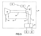
- the process 26, 28 downstream of the turbine 14 is a separate system outside the control volume 16 of the gas turbine engine which ideally do not influence operating conditions of the gas turbine engine.
- the system outside the control volume 16 of the gas turbine engine may influence the operating conditions of the gas turbine engine, such as due to back pressure for example.
Landscapes
- Engineering & Computer Science (AREA)
- Chemical & Material Sciences (AREA)
- Combustion & Propulsion (AREA)
- Mechanical Engineering (AREA)
- General Engineering & Computer Science (AREA)
- Engine Equipment That Uses Special Cycles (AREA)
Abstract
Description
Claims (10)
- A gas turbine engine comprising:a compressor [10] having an inlet and an outlet, the compressor [10] being configured to receive a coolant fluid stream [30], to compress the coolant fluid stream [22] and to discharge the compressed coolant fluid stream [22];a turbine [14] in fluid communication with the compressor [10] for receiving the compressed coolant fluid stream [22] from the compressor [10] outlet, the compressed coolant fluid stream [22] undergoing thermal exchange with the turbine [14] and exiting the turbine [14] thereafter; anda source [18] of a working fluid stream [44] in fluid communication with the turbine [14], the working fluid stream [44] being fluidly isolated from at least a portion of the coolant fluid stream [22], undergoing thermodynamic expansion through the turbine [14] to extract energy therefrom and exiting the turbine [14] thereafter, a portion of the extracted energy being utilized to drive the compressor [10].
- The gas turbine engine of claim 1, wherein at least a portion of the coolant fluid stream [22] being preheated in the turbine 14 is channeled downstream of the turbine [14] to supply a preheated process fluid stream [24] to an adjacent system [26].
- The gas turbine engine of claim 2, wherein at least a portion of the working fluid stream [44] mixes with at least a portion of the coolant fluid stream [22] downstream of the turbine [14] to supply the preheated process fluid stream [24, 12] to the system [26] outside a control volume [16] of the gas turbine engine.
- The gas turbine engine of claim 1, wherein the working fluid stream [44] and the coolant fluid stream [22] enter into a heat exchanger [46] downstream of the turbine [14] to undergo thermal exchange and supply a preheated process fluid stream [24, 12] to the system [26, 48] outside a control volume [16] of the gas turbine engine.
- A gas turbine engine comprising:wherein at least a portion of the coolant fluid stream [22] being preheated in the turbine 14 is channeled downstream of the turbine [14] to supply a preheated process fluid stream [24] to an adjacent system [26].a compressor [10] having an inlet and outlet, the compressor [10] being configured to receive a coolant fluid stream [30], to compress the coolant fluid stream and to discharge the compressed coolant fluid stream [22];a turbine [14] in fluid communication with the compressor [10] for receiving the compressed coolant fluid stream [22] from the compressor [10] outlet, the compressed coolant fluid stream [22] undergoing thermal exchange within the turbine [14] and exiting the turbine [14] thereafter; anda source of a working fluid stream [44] in fluid communication with the turbine [14], the working fluid stream [44] being fluidly isolated from a portion of the coolant fluid stream [22] and undergoing thermodynamic expansion through the turbine [14] to extract energy therefrom;
- The gas turbine engine of claim 5, wherein the working fluid stream [44] and the coolant fluid stream [22] undergoing thermal exchange in a heat exchanger [46] downstream of the turbine [14] to supply a preheated process fluid stream to the system outside the control volume of the gas turbine engine.
- The gas turbine engine of claim 5, wherein a portion of the energy extracted from the thermodynamic expansion of the working fluid stream [44] being utilized to drive the compressor [10].
- The gas turbine engine of claim 5, wherein at least a portion of the coolant fluid stream [22] is channeled downstream of the turbine [14] and mixed with the working fluid stream [44] to supply the preheated process fluid stream [24] to the system [26] outside the control volume [16] of the gas turbine engine.
- A method for power generation of gas turbine engine comprising:compressing a coolant fluid stream [30] in a compressor [10];transferring the compressed coolant fluid stream [22] from the compressor [10] to a turbine [14], the turbine [14] being in fluid communication with the compressor [10];transferring heat between the coolant fluid stream [22] and the turbine [14], the coolant fluid stream [22] exiting the turbine [14] thereafter;receiving a working fluid stream [44] to the turbine [14] from a source [18] of a working fluid stream [44] in fluid communication with the turbine [14], the working fluid stream [44] being fluidly isolated from a portion of the coolant fluid stream [22]; andexpanding thermodynamically the working fluid stream [44] extracting energy therefrom, the working fluid stream [44] exiting the turbine [14] thereafter, a portion of the extracted energy driving the compressor [10].
- The method of claim 9, further comprising:transferring heat between the working fluid stream [44] and the coolant fluid stream [22] downstream of the turbine [14];supplying a preheated process fluid stream [24] to an adjacent system [26].
Applications Claiming Priority (2)
| Application Number | Priority Date | Filing Date | Title |
|---|---|---|---|
| US10/331,342 US6978621B2 (en) | 2002-12-31 | 2002-12-31 | Turbo recuperator device |
| US331342 | 2002-12-31 |
Publications (3)
| Publication Number | Publication Date |
|---|---|
| EP1435433A2 true EP1435433A2 (en) | 2004-07-07 |
| EP1435433A3 EP1435433A3 (en) | 2006-10-04 |
| EP1435433B1 EP1435433B1 (en) | 2014-10-01 |
Family
ID=32507357
Family Applications (1)
| Application Number | Title | Priority Date | Filing Date |
|---|---|---|---|
| EP03258128.2A Expired - Lifetime EP1435433B1 (en) | 2002-12-31 | 2003-12-22 | Turbo recuperator device |
Country Status (4)
| Country | Link |
|---|---|
| US (1) | US6978621B2 (en) |
| EP (1) | EP1435433B1 (en) |
| AU (1) | AU2003266435B8 (en) |
| CA (1) | CA2453634C (en) |
Families Citing this family (11)
| Publication number | Priority date | Publication date | Assignee | Title |
|---|---|---|---|---|
| US7093446B2 (en) * | 2004-09-15 | 2006-08-22 | General Electric Company | Gas turbine engine having improved core system |
| US7096674B2 (en) * | 2004-09-15 | 2006-08-29 | General Electric Company | High thrust gas turbine engine with improved core system |
| US8015826B2 (en) * | 2007-04-05 | 2011-09-13 | Siemens Energy, Inc. | Engine brake for part load CO reduction |
| US8033116B2 (en) * | 2008-05-06 | 2011-10-11 | General Electric Company | Turbomachine and a method for enhancing power efficiency in a turbomachine |
| US7818969B1 (en) | 2009-12-18 | 2010-10-26 | Energyield, Llc | Enhanced efficiency turbine |
| US8820091B2 (en) * | 2012-11-07 | 2014-09-02 | Siemens Aktiengesellschaft | External cooling fluid injection system in a gas turbine engine |
| US9976448B2 (en) | 2015-05-29 | 2018-05-22 | General Electric Company | Regenerative thermodynamic power generation cycle systems, and methods for operating thereof |
| CN114754024A (en) * | 2021-01-12 | 2022-07-15 | 海德韦尔(太仓)能源科技有限公司 | Compressor, air compressor comprising compressor and fuel cell device |
| CN112796886B (en) * | 2021-01-29 | 2023-03-31 | 哈尔滨工业大学 | Reheating type combined cycle system of fuel cell chemical backheating gas turbine |
| US12253033B2 (en) | 2022-10-04 | 2025-03-18 | General Electric Company | Hydrogen fuel leak detection system for a vehicle |
| US12540559B2 (en) * | 2023-02-09 | 2026-02-03 | Flibe Energy, Inc. | sCO2 power conversion system |
Family Cites Families (11)
| Publication number | Priority date | Publication date | Assignee | Title |
|---|---|---|---|---|
| NL8901348A (en) * | 1989-05-29 | 1990-12-17 | Turboconsult Bv | METHOD AND APPARATUS FOR GENERATING ELECTRICAL ENERGY |
| US5948221A (en) * | 1994-08-08 | 1999-09-07 | Ztek Corporation | Pressurized, integrated electrochemical converter energy system |
| US6105362A (en) * | 1995-09-22 | 2000-08-22 | Kabushiki Kaisha Toshiba | Combined cycle power plant with gas turbine cooling system |
| US5611197A (en) | 1995-10-23 | 1997-03-18 | General Electric Company | Closed-circuit air cooled turbine |
| US6098395A (en) * | 1996-04-04 | 2000-08-08 | Siemens Westinghouse Power Corporation | Closed-loop air cooling system for a turbine engine |
| US5782076A (en) * | 1996-05-17 | 1998-07-21 | Westinghouse Electric Corporation | Closed loop air cooling system for combustion turbines |
| GB2346177B (en) * | 1999-02-01 | 2003-03-19 | Alstom Gas Turbines Ltd | Gas turbine engine |
| US6295803B1 (en) * | 1999-10-28 | 2001-10-02 | Siemens Westinghouse Power Corporation | Gas turbine cooling system |
| US6691519B2 (en) * | 2000-02-18 | 2004-02-17 | Siemens Westinghouse Power Corporation | Adaptable modular gas turbine power plant |
| JP3593488B2 (en) * | 2000-02-25 | 2004-11-24 | 株式会社日立製作所 | gas turbine |
| DE10027833A1 (en) * | 2000-06-05 | 2001-12-13 | Alstom Power Nv | Method for cooling a gas turbine system and gas turbine system for carrying out the method |
-
2002
- 2002-12-31 US US10/331,342 patent/US6978621B2/en not_active Expired - Fee Related
-
2003
- 2003-12-03 AU AU2003266435A patent/AU2003266435B8/en not_active Ceased
- 2003-12-18 CA CA2453634A patent/CA2453634C/en not_active Expired - Fee Related
- 2003-12-22 EP EP03258128.2A patent/EP1435433B1/en not_active Expired - Lifetime
Also Published As
| Publication number | Publication date |
|---|---|
| EP1435433B1 (en) | 2014-10-01 |
| AU2003266435B2 (en) | 2009-05-28 |
| US20040123602A1 (en) | 2004-07-01 |
| US6978621B2 (en) | 2005-12-27 |
| CA2453634A1 (en) | 2004-06-30 |
| EP1435433A3 (en) | 2006-10-04 |
| CA2453634C (en) | 2013-02-12 |
| AU2003266435A1 (en) | 2004-07-15 |
| AU2003266435B8 (en) | 2009-06-04 |
Similar Documents
| Publication | Publication Date | Title |
|---|---|---|
| EP1033484B1 (en) | Gas turbine cooling system | |
| US20040088995A1 (en) | Method for cooling a gas turbine and gas turbine installation | |
| CN106715840B (en) | Power generation system and method for generating power | |
| US6389793B1 (en) | Combustion turbine cooling media supply system and related method | |
| US5611197A (en) | Closed-circuit air cooled turbine | |
| US5640840A (en) | Recuperative steam cooled gas turbine method and apparatus | |
| EP0656468A1 (en) | Gas turbine vane cooling system | |
| US20110162386A1 (en) | Ejector-OBB Scheme for a Gas Turbine | |
| EP2426314A2 (en) | System and method of cooling turbine airfoils with carbon dioxide | |
| JPH0396628A (en) | Cooling gas turbine engine by steam | |
| EP3845742B1 (en) | Systems and methods for operating a turbocharged gas turbine engine | |
| EP4517067A1 (en) | Partial exhaust condensation intercooling | |
| EP3683421B1 (en) | Work recovery system for a gas turbine engine utilizing a recuperated supercritical co2 cycle driven by cooling air waste heat | |
| EP1435433B1 (en) | Turbo recuperator device | |
| JPH11200807A (en) | Refrigerant recovery type gas turbine and its stationary blade | |
| EP2570592A2 (en) | Method and apparatus for controlling temperature of gas turbine components | |
| JP2001107748A (en) | Gas turbine plant | |
| CN107429613B (en) | Turbine Cooling Blades for Gas Turbine Engines | |
| US5873233A (en) | Method of operating a gas-turbine group | |
| JPH0988518A (en) | Combined power plant |
Legal Events
| Date | Code | Title | Description |
|---|---|---|---|
| PUAI | Public reference made under article 153(3) epc to a published international application that has entered the european phase |
Free format text: ORIGINAL CODE: 0009012 |
|
| AK | Designated contracting states |
Kind code of ref document: A2 Designated state(s): AT BE BG CH CY CZ DE DK EE ES FI FR GB GR HU IE IT LI LU MC NL PT RO SE SI SK TR |
|
| AX | Request for extension of the european patent |
Extension state: AL LT LV MK |
|
| PUAL | Search report despatched |
Free format text: ORIGINAL CODE: 0009013 |
|
| AK | Designated contracting states |
Kind code of ref document: A3 Designated state(s): AT BE BG CH CY CZ DE DK EE ES FI FR GB GR HU IE IT LI LU MC NL PT RO SE SI SK TR |
|
| AX | Request for extension of the european patent |
Extension state: AL LT LV MK |
|
| 17P | Request for examination filed |
Effective date: 20070404 |
|
| AKX | Designation fees paid |
Designated state(s): DE FR GB |
|
| 17Q | First examination report despatched |
Effective date: 20070627 |
|
| REG | Reference to a national code |
Ref country code: DE Ref legal event code: R079 Ref document number: 60346815 Country of ref document: DE Free format text: PREVIOUS MAIN CLASS: F01D0013020000 Ipc: F02C0007180000 |
|
| RIC1 | Information provided on ipc code assigned before grant |
Ipc: F02C 7/12 20060101ALI20140303BHEP Ipc: F01D 13/02 20060101ALI20140303BHEP Ipc: F02C 3/04 20060101ALI20140303BHEP Ipc: F02C 7/18 20060101AFI20140303BHEP Ipc: F02C 6/08 20060101ALI20140303BHEP Ipc: F02C 6/18 20060101ALI20140303BHEP |
|
| GRAP | Despatch of communication of intention to grant a patent |
Free format text: ORIGINAL CODE: EPIDOSNIGR1 |
|
| INTG | Intention to grant announced |
Effective date: 20140428 |
|
| GRAS | Grant fee paid |
Free format text: ORIGINAL CODE: EPIDOSNIGR3 |
|
| GRAA | (expected) grant |
Free format text: ORIGINAL CODE: 0009210 |
|
| AK | Designated contracting states |
Kind code of ref document: B1 Designated state(s): DE FR GB |
|
| REG | Reference to a national code |
Ref country code: GB Ref legal event code: FG4D |
|
| REG | Reference to a national code |
Ref country code: DE Ref legal event code: R096 Ref document number: 60346815 Country of ref document: DE Effective date: 20141113 |
|
| REG | Reference to a national code |
Ref country code: DE Ref legal event code: R097 Ref document number: 60346815 Country of ref document: DE |
|
| PLBE | No opposition filed within time limit |
Free format text: ORIGINAL CODE: 0009261 |
|
| STAA | Information on the status of an ep patent application or granted ep patent |
Free format text: STATUS: NO OPPOSITION FILED WITHIN TIME LIMIT |
|
| 26N | No opposition filed |
Effective date: 20150702 |
|
| REG | Reference to a national code |
Ref country code: FR Ref legal event code: PLFP Year of fee payment: 13 |
|
| PGFP | Annual fee paid to national office [announced via postgrant information from national office to epo] |
Ref country code: GB Payment date: 20151229 Year of fee payment: 13 |
|
| PGFP | Annual fee paid to national office [announced via postgrant information from national office to epo] |
Ref country code: FR Payment date: 20151217 Year of fee payment: 13 |
|
| PGFP | Annual fee paid to national office [announced via postgrant information from national office to epo] |
Ref country code: DE Payment date: 20151229 Year of fee payment: 13 |
|
| REG | Reference to a national code |
Ref country code: DE Ref legal event code: R119 Ref document number: 60346815 Country of ref document: DE |
|
| GBPC | Gb: european patent ceased through non-payment of renewal fee |
Effective date: 20161222 |
|
| REG | Reference to a national code |
Ref country code: FR Ref legal event code: ST Effective date: 20170831 |
|
| PG25 | Lapsed in a contracting state [announced via postgrant information from national office to epo] |
Ref country code: FR Free format text: LAPSE BECAUSE OF NON-PAYMENT OF DUE FEES Effective date: 20170102 |
|
| PG25 | Lapsed in a contracting state [announced via postgrant information from national office to epo] |
Ref country code: GB Free format text: LAPSE BECAUSE OF NON-PAYMENT OF DUE FEES Effective date: 20161222 Ref country code: DE Free format text: LAPSE BECAUSE OF NON-PAYMENT OF DUE FEES Effective date: 20170701 |