EP1435342A1 - Procédé et installation de controle de la dispersion modale de polarisation d'une fibre optique lors du fibrage - Google Patents
Procédé et installation de controle de la dispersion modale de polarisation d'une fibre optique lors du fibrage Download PDFInfo
- Publication number
- EP1435342A1 EP1435342A1 EP03293068A EP03293068A EP1435342A1 EP 1435342 A1 EP1435342 A1 EP 1435342A1 EP 03293068 A EP03293068 A EP 03293068A EP 03293068 A EP03293068 A EP 03293068A EP 1435342 A1 EP1435342 A1 EP 1435342A1
- Authority
- EP
- European Patent Office
- Prior art keywords
- fiber
- pulley
- image
- movement
- relative
- Prior art date
- Legal status (The legal status is an assumption and is not a legal conclusion. Google has not performed a legal analysis and makes no representation as to the accuracy of the status listed.)
- Granted
Links
- 238000000034 method Methods 0.000 title claims abstract description 22
- 239000006185 dispersion Substances 0.000 title claims abstract description 18
- 239000013307 optical fiber Substances 0.000 title claims abstract description 14
- 230000008569 process Effects 0.000 title description 7
- 239000000835 fiber Substances 0.000 claims abstract description 147
- 238000009434 installation Methods 0.000 claims abstract description 19
- 230000010287 polarization Effects 0.000 claims abstract description 16
- 238000004458 analytical method Methods 0.000 claims description 16
- 238000012681 fiber drawing Methods 0.000 claims description 11
- 238000004364 calculation method Methods 0.000 claims description 10
- 238000010191 image analysis Methods 0.000 claims description 5
- 238000006073 displacement reaction Methods 0.000 claims description 4
- 230000010355 oscillation Effects 0.000 description 23
- 238000005259 measurement Methods 0.000 description 7
- 239000011248 coating agent Substances 0.000 description 4
- 238000000576 coating method Methods 0.000 description 4
- 230000000737 periodic effect Effects 0.000 description 4
- 230000008901 benefit Effects 0.000 description 3
- 230000000694 effects Effects 0.000 description 3
- 230000009467 reduction Effects 0.000 description 3
- 238000001228 spectrum Methods 0.000 description 3
- 238000010586 diagram Methods 0.000 description 2
- 238000004519 manufacturing process Methods 0.000 description 2
- 238000012360 testing method Methods 0.000 description 2
- 230000008859 change Effects 0.000 description 1
- 230000007547 defect Effects 0.000 description 1
- 230000001419 dependent effect Effects 0.000 description 1
- 238000004033 diameter control Methods 0.000 description 1
- 229940082150 encore Drugs 0.000 description 1
- 238000007380 fibre production Methods 0.000 description 1
- 238000012544 monitoring process Methods 0.000 description 1
- 230000003287 optical effect Effects 0.000 description 1
- 238000005096 rolling process Methods 0.000 description 1
- 230000009466 transformation Effects 0.000 description 1
- 238000013519 translation Methods 0.000 description 1
Images
Classifications
-
- C—CHEMISTRY; METALLURGY
- C03—GLASS; MINERAL OR SLAG WOOL
- C03B—MANUFACTURE, SHAPING, OR SUPPLEMENTARY PROCESSES
- C03B37/00—Manufacture or treatment of flakes, fibres, or filaments from softened glass, minerals, or slags
- C03B37/01—Manufacture of glass fibres or filaments
- C03B37/02—Manufacture of glass fibres or filaments by drawing or extruding, e.g. direct drawing of molten glass from nozzles; Cooling fins therefor
- C03B37/03—Drawing means, e.g. drawing drums ; Traction or tensioning devices
-
- C—CHEMISTRY; METALLURGY
- C03—GLASS; MINERAL OR SLAG WOOL
- C03B—MANUFACTURE, SHAPING, OR SUPPLEMENTARY PROCESSES
- C03B37/00—Manufacture or treatment of flakes, fibres, or filaments from softened glass, minerals, or slags
- C03B37/01—Manufacture of glass fibres or filaments
- C03B37/02—Manufacture of glass fibres or filaments by drawing or extruding, e.g. direct drawing of molten glass from nozzles; Cooling fins therefor
- C03B37/025—Manufacture of glass fibres or filaments by drawing or extruding, e.g. direct drawing of molten glass from nozzles; Cooling fins therefor from reheated softened tubes, rods, fibres or filaments, e.g. drawing fibres from preforms
- C03B37/0253—Controlling or regulating
-
- C—CHEMISTRY; METALLURGY
- C03—GLASS; MINERAL OR SLAG WOOL
- C03B—MANUFACTURE, SHAPING, OR SUPPLEMENTARY PROCESSES
- C03B2203/00—Fibre product details, e.g. structure, shape
- C03B2203/10—Internal structure or shape details
- C03B2203/18—Axial perturbations, e.g. in refractive index or composition
- C03B2203/19—Alternating positive/negative spins or twists
-
- C—CHEMISTRY; METALLURGY
- C03—GLASS; MINERAL OR SLAG WOOL
- C03B—MANUFACTURE, SHAPING, OR SUPPLEMENTARY PROCESSES
- C03B2203/00—Fibre product details, e.g. structure, shape
- C03B2203/36—Dispersion modified fibres, e.g. wavelength or polarisation shifted, flattened or compensating fibres (DSF, DFF, DCF)
-
- C—CHEMISTRY; METALLURGY
- C03—GLASS; MINERAL OR SLAG WOOL
- C03B—MANUFACTURE, SHAPING, OR SUPPLEMENTARY PROCESSES
- C03B2205/00—Fibre drawing or extruding details
- C03B2205/06—Rotating the fibre fibre about its longitudinal axis
Definitions
- the present invention relates to optical fibers and more specifically the reduction of the polarization modal dispersion during the manufacture of such fibers.
- EP-B-0 582 405 describes a conventional fiberizing installation, in which a preform is heated at its end; the heated end of the preform is stretched to form an optical fiber.
- the installation includes various stations, for the diameter control, coating application, concentricity control and of the coating thickness, the hardening of the coating.
- the fiber is wound on pulleys and driven by a draft capstan, before being wound on a coil or drum.
- This document proposes, to reduce the modal dispersion of polarization, that one of the fiber guide pulleys is moving alternative rotation around an axis included in the fiber drawing plane.
- This movement oscillation has the effect of rolling the fiber on the surface of the pulley, both and on the other of the fiber drawing plane defined by the axis of the preform and the fiber.
- This movement lateral of the fiber induces a twist in the fiber being stretched and a permanent deformation.
- the alternation in the movement of the pulley has the effect apply twists to the fiber in alternating directions, reducing the polarization modal dispersion.
- EP-A-0 744 636 proposes a solution allowing avoid reciprocating movement of the pulley; this document proposes to use a pulley with a left surface, with a simple rotational movement. In rotation, the left pulley presents to the fiber a surface equivalent to that of a wheel with symmetry of revolution whose axis is driven by an alternating movement.
- WO-A-98 46536 describes another system for applying torsion to the fiber. Elements are in contact with the fiber, on both sides of the latter. One of elements is driven in an alternating movement.
- a problem presented by this solution is that of determining the twist applied to the fiber, or rotation of the fiber on the oscillating device. This problem is all the more complex as the fiber has a typical dimension of on the order of 250 ⁇ m, has a cylindrical shape and is stretched at speeds that can reach 1500 m / min.
- WO-A-01 33184 indicates that it is known to introduce bubbles into the fiber or other irregularities. It is then possible, for a given adjustment of the movement oscillation of the pulley, measure the applied twist on the stretched fiber. Such However, this involves stretching the fiber before the measurements can be taken. he leads to wasted time and fiber. In addition, it involves a new measure to each change in the characteristics of the stretching device - preform, type of coating, fiber speed, etc. Finally, the measurement is not performed on the fiber, but on a specific preform, which poses a problem of reproducibility of the process.
- WO-A-01 33184 also proposes to measure the diameter of the fiber and calculate a Fourier transformation of the diameter.
- the power spectrum correspondent has peaks at a frequency 2v, with v the inversion frequency of the pulley oscillation.
- the amplitude of the torsion is obtained from the spectrum, by calculating the amplitude of the spectrum peaks.
- This solution requires having a device for precise measurement of the diameter of the fiber and calculation means developed. This solution is also limited in principle even to oscillations periodicals of the anti polar modal dispersion system.
- the part is a pulley driven by a oscillating movement.
- the image sensor is adapted to capture an image of the fiber and pulley near the midpoint of contact between the fiber and the pulley.
- the invention proposes to capture images of the fiber on the pulley of the fiberizing or stretching installation which limits the polarization modal dispersion, to determine the position of the fiber relative to the pulley and then to deduce the rotation applied to the fiber from the images obtained.
- Image analysis allows to know precisely the position of the fiber on the pulley and therefore the angle formed between the fiber and the pulley. We can therefore deduce the torsion applied to the fiber.
- the process does not involve any special equipment for calibration and can be used continuously during fiber production. It does not involve complex calculations and applies to all types of oscillation movements.
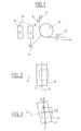
- FIG. 1 is a schematic view of a installation in which the invention is implemented; only the elements necessary for understanding the invention.
- the figure shows fiber 2 during fiber drawing, the direction of movement of this fiber being symbolized by the arrow 4.
- Two guide pulleys 6, 8 guide the fiber before it does not reach the oscillating pulley 10.
- This oscillating pulley is driven by a movement alternative rotation around the axis of arrival of the fiber - which is vertical in the figure.
- This movement typically has a frequency of a few Hz for a system of fiberizing operating at a speed typically between 200 and 1800 m / min, with a maximum displacement angle which can typically reach ⁇ 9 ° compared to the fiber drawing plan.
- the oscillating movement of the pulley causes a twist in the fiber, in alternating directions of rotation, which has the effect of reducing the polarization modal dispersion.
- the fiber is guided by fingers 12, then it passes over the drive device before being wound up in a manner known per se.
- the invention is based on the fact that the twist applied to the current fiber drawing is a function of the position of the fiber 2 on the oscillating pulley 10; so the measurement of the position of the fiber makes it possible to determine, as explained now, the twist applied to the fiber.
- the figure therefore shows an image sensor 14.
- the sensor is adapted to provide an image of the fiber on the pulley; we can use for facilitate the installation of the sensor of the optical means, such as the mirror 16 of the figure, which returns to the sensor the image of the fiber on the pulley. Images supplied by the sensor 14 are transmitted to an analysis circuit 18.
- the image sensor is for example a high frequency camera, which captures images with a frequency of 100 images per second.
- a frequency allows at least 20 images of the fiber on the pulley for each cycle of the oscillating pulley and determine the movement of the fiber on the pulley oscillating.
- the number of images for each cycle of the oscillating pulley depends on the nature of the pulley movement; for a simple movement of the pulley, i! fewer images may be sufficient for each pulley cycle.
- the images provided by the image sensor are transmitted to the circuit analysis, in which they are analyzed to determine the position of the fiber on pulley.
- the analysis circuit is for example made up of a microcomputer of the type PC, equipped with a port for receiving images supplied by the image sensor and a pattern recognition software, such as software sold under the brand Labview. This software is programmed to determine in a picture the position of the fiber relative to the oscillating pulley, more precisely the angle between the pulley and the fiber. You can also use image processing software.
- Figures 2 and 3 show schematic representations of the images captured in the installation of figure 1.
- Figure 2 shows the position of the pulley for a zero oscillation angle
- Figure 3 shows the position of the pulley for a maximum oscillation angle of the pulley.
- the reference 10 represents the pulley and the reference 22 designates the axis of rotation of the pulley for the drive of fiber 2.
- Reference 24 designates the fiber drawing plane.
- the oscillation axis of the pulley forms an angle of 45 ° with respect to the plane of Figures 2 and 3.
- Reference 26 represents the contours of the image captured by the image sensor 14.
- the pulley forms a zero angle with the fiber drawing plane 24, which is in this position confused with the median plane of the pulley.
- the angle ⁇ between the pulley and fiber is zero.
- This position corresponds to the position of a pulley of a classic system, without oscillation of the pulley to reduce the polarization modal dispersion.
- the pulley has rotated by an angle ⁇ in its swinging motion.
- the fiber has moved relative to the pulley, from so that the fiber forms with the pulley - with the edge or the median plane of the pulley - an angle ⁇ .
- the reference 24 in FIG. 3 also shows the image captured by the image sensor 14. It is understood that this image makes it possible to measure the angle ⁇ , in recognizing fiber 2 in the image and knowing the angle of oscillation of the pulley or by determining from the image the position of the pulley relative to the fiber.
- This angle is representative of the number of turns the fiber of which has rolled on the surface of the pulley and is therefore representative of the twist applied to the fiber.
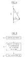
- Figure 4 shows a block diagram of the fiber and pulley speeds to explain the above formula.
- the figure shows the axis 28 of the fiber and the median plane 30 of the pulley.
- the figure shows the speed V F of the fiber, the speed V P on the surface of the pulley as well as the speed of rotation V ROT of the fiber or transverse speed of the fiber.
- the figure shows the angle ⁇ between the speed of the fiber and the speed of the pulley.
- Tests have been carried out with a fiberizing installation of the type shown in FIG. 1.
- a fiber drawing speed of 600 is applied m / min, a pulley oscillation frequency of 4.5 Hz and an oscillation angle of ⁇ 8 °.
- This configuration conventionally gives an average rotation speed of the fiber 6 rpm.
- the application of the process makes it possible to find this value, with image capture at a frequency of 4.6 Hz and analysis on images corresponding to a half period.
- This configuration conventionally gives a speed of fiber rotation of 4.3 rpm.
- the application of the process described with reference to figures again provides this value.
- Analysis of the images in the analysis circuit 18 of the images supplied by the image sensor 14 thus makes it possible to determine the twist applied to the fiber. It is then possible, in real time or almost in real time, to adjust the parameters oscillation of the oscillating pulley - in particular the frequency of oscillation or the amplitude of oscillation.
- the adjustment of these parameters is represented in the figure by the arrow 20 connecting the analysis circuit 18 and the oscillating pulley.
- FIG. 5 is a flowchart of the method of the invention.
- Step 34 is an image analysis step to determine the position of the fiber.
- Step 36 is a step of calculating the twist from the position determined in step 34.
- the method described with reference to FIG. 1 has the advantage of being able to apply not only to an oscillating pulley, as in the example of the figure, but more generally to any system for reducing modal dispersion polarization, like those of the state of the art mentioned above. he can be used for a triangular movement of the pulley - i.e. for a movement at constant angular speed over each half period of oscillation; he also applies to other movements, for example sinusoidal oscillations. Unlike the solutions proposed in the state of the art, the process applies during fiber manufacturing, without the need to calibrate the fiberizing apparatus with a specific preform. This results in an economy of time and resources, as well as greater reliability of the results obtained.
- the method also makes it possible to view the average speed of rotation of the fiber, which allows oscillation movement to be controlled in real time; it allows also to determine the evolution of the rotation speed over one or more periods of operation of the polarization modal dispersion reduction system. This information can be used not only to adjust this system of reduction, but also for monitoring the alignment of the equipment.
- the invention is not limited to the exemplary embodiments mentioned above; so it applies to a different configuration of the device of fiberizing.
- the invention could also be applied to movements other than a oscillating movement in rotation of the pulley, as an alternative movement in translation; in this case, the above formula could be adapted, the rotation can be calculated by dividing the horizontal displacement of the roller with respect to the fiber by the circumference of the fiber.
- the part applying the twist to the fiber is not not limited to a pulley but may have another shape.
- the process applies not only to periodic movements, but also anti modal dispersion systems of polarization with aperiodic or pseudo-periodic movements.
Landscapes
- Chemical & Material Sciences (AREA)
- Engineering & Computer Science (AREA)
- Materials Engineering (AREA)
- Geochemistry & Mineralogy (AREA)
- Manufacturing & Machinery (AREA)
- General Life Sciences & Earth Sciences (AREA)
- Life Sciences & Earth Sciences (AREA)
- Organic Chemistry (AREA)
- Manufacture, Treatment Of Glass Fibers (AREA)
- Testing Of Optical Devices Or Fibers (AREA)
- Optical Fibers, Optical Fiber Cores, And Optical Fiber Bundles (AREA)
- Length Measuring Devices By Optical Means (AREA)
- Mechanical Coupling Of Light Guides (AREA)
Abstract
Description
- l'application à la fibre d'une torsion par déplacement de la fibre par rapport à une pièce ;
- la prise d'au moins une image de la fibre et de la pièce;
- l'analyse de l'image pour déterminer la position de la fibre par rapport à la pièce, et
- le calcul de la torsion appliquée à la fibre à partir de la position déterminée. Dans un mode de mise en oeuvre, l'étape d'application comprend le déplacement en rotation de la pièce par rapport à la fibre et l'étape d'analyse comprend la détermination de la position angulaire de la fibre par rapport à la pièce.L'étape d'application comprend avantageusement le déplacement périodique de la pièce. On peut alors prévoir que l'étape de prise d'image s'effectue périodiquement, avec une période différente de celle du déplacement de la pièce.Dans un mode de mise en oeuvre, l'étape de calcul s'effectue par calcul du nombre de tours dont la fibre roule sur la pièce. Dans ce cas, l'étape de calcul peut comprendre le calcul de la position moyenne de la fibre par intégration des positions.L'invention propose encore une installation d'étirage d'une fibre optique, comprenant
- une pièce en déplacement, le déplacement de la pièce appliquant une torsion à la fibre;
- un capteur d'image adapté à capter des images de la fibre et de la pièce;
- un circuit d'analyse des images captées adapté à déterminer la position de la fibre par rapport à la pièce et à calculer à partir de la position déterminée la torsion appliquée à la fibre.
- figure 1, une vue schématique d'une installation dans laquelle l'invention est mise en oeuvre;
- figure 2 et 3, des représentations schématiques des images captées dans l'installation de la figure 1, à des instants différents;
- figure 4, un schéma de principe des vitesses de la fibre et de la poulie;
- figure 5, un ordinogramme du procédé de l'invention.
Claims (9)
- Un procédé de contrôle de la dispersion modale de polarisation d'une fibre optique (2) lors du fibrage, comprenant :l'application à la fibre (2) d'une torsion par déplacement de la fibre par rapport à une pièce (10);la prise d'au moins une image (24) de la fibre (2) et de la pièce (10);l'analyse de l'image pour déterminer la position de la fibre (2) par rapport à la pièce (10), etle calcul de la torsion appliquée à la fibre (2) à partir de la position déterminée.
- Le procédé de la revendication 1, caractérisé en ce que l'étape d'application comprend le déplacement en rotation de la pièce (10) par rapport à la fibre (2) et en ce que l'étape d'analyse comprend la détermination de la position angulaire de la fibre (2) par rapport à la pièce (10).
- Le procédé de la revendication 1 ou 2, caractérisé en ce que l'étape d'application comprend le déplacement périodique de la pièce (10).
- Le procédé de la revendication 3, caractérisé en ce que l'étape de prise d'image s'effectue périodiquement, avec une période différente de celle du déplacement de la pièce.
- Le procédé de l'une des revendications 1 à 4, caractérisé en ce que l'étape de calcul s'effectue par calcul du nombre de tours dont la fibre (2) roule sur la pièce (10).
- Le procédé de la revendication 5, caractérisé en ce que l'étape de calcul comprend le calcul de la position moyenne de la fibre par intégration des positions.
- Une installation d'étirage d'une fibre optique (2), comprenantune pièce (10) en déplacement, le déplacement de la pièce appliquant une torsion à la fibre (2);un capteur d'image (14) adapté à capter des images de la fibre (2) et de la pièce (10);un circuit d'analyse (18) des images captées adapté à déterminer la position de la fibre (2) par rapport à la pièce et à calculer à partir de la position déterminée la torsion appliquée à la fibre (2).
- L'installation de la revendication 7, caractérisée en ce que la pièce (10) est une poulie animée d'un mouvement oscillant.
- L'installation de la revendication 8, caractérisée en ce que le capteur d'images (14) est adapté à capter une image de la fibre (2) et de la poulie (10) au voisinage du point médian de contact entre la fibre et la poulie.
Liste des références 2 fibre 4 sens déplacement 6 poulie de guidage 8 poulie de guidage 10 poulie oscillante 12 doigts de guidage 14 capteur d'images 16 miroir 18 circuit d'analyse 20 flèche 22 axe poulie 24 plan de fibrage 26 contour image 28 axe de la fibre 30 plan médian de la poulie 32 prise d'images 34 analyse des images 36 calcul de la torsion
Applications Claiming Priority (2)
| Application Number | Priority Date | Filing Date | Title |
|---|---|---|---|
| FR0216890A FR2849438B1 (fr) | 2002-12-31 | 2002-12-31 | Procede de controle de la dispersion modale de polarisation d'une fibre optique lors du fibrage |
| FR0216890 | 2002-12-31 |
Publications (2)
| Publication Number | Publication Date |
|---|---|
| EP1435342A1 true EP1435342A1 (fr) | 2004-07-07 |
| EP1435342B1 EP1435342B1 (fr) | 2010-11-03 |
Family
ID=32480310
Family Applications (1)
| Application Number | Title | Priority Date | Filing Date |
|---|---|---|---|
| EP03293068A Expired - Lifetime EP1435342B1 (fr) | 2002-12-31 | 2003-12-08 | Procédé et installation de contrôle de la dispersion modale de polarisation d'une fibre optique lors du fibrage |
Country Status (7)
| Country | Link |
|---|---|
| US (1) | US7284397B2 (fr) |
| EP (1) | EP1435342B1 (fr) |
| CN (1) | CN1304313C (fr) |
| AT (1) | ATE486824T1 (fr) |
| DE (1) | DE60334768D1 (fr) |
| DK (1) | DK1435342T3 (fr) |
| FR (1) | FR2849438B1 (fr) |
Families Citing this family (5)
| Publication number | Priority date | Publication date | Assignee | Title |
|---|---|---|---|---|
| US20080141723A1 (en) * | 2004-12-02 | 2008-06-19 | Franco Cocchini | Method, System and Device for Imparting a Predetermined Rotation to an Optical Fibre |
| WO2010050079A1 (fr) * | 2008-10-31 | 2010-05-06 | 株式会社フジクラ | Dispositif de fabrication d'une fibre optique et procédé de fabrication d'une fibre optique |
| CN103993001A (zh) * | 2014-06-10 | 2014-08-20 | 中山大学 | 一种微颗粒或生物细胞的群体捕获和迁移方法 |
| WO2023095916A1 (fr) * | 2021-11-29 | 2023-06-01 | 住友電気工業株式会社 | Procédé de mesure de torsion de fibre optique et procédé de fabrication de fibre optique |
| WO2025121332A1 (fr) * | 2023-12-04 | 2025-06-12 | 住友電気工業株式会社 | Procédé de fabrication de fibre optique |
Citations (3)
| Publication number | Priority date | Publication date | Assignee | Title |
|---|---|---|---|---|
| WO2000069782A1 (fr) * | 1999-05-14 | 2000-11-23 | Fujikura Ltd. | Procede de mesure de la torsion d'une fibre optique et procede et dispositif de fabrication de fibre optique et dispositif associe |
| WO2002032820A2 (fr) | 2000-10-18 | 2002-04-25 | Corning Incorporated | Fibre a dispersion commandee non constante |
| EP1258751A1 (fr) | 1999-11-08 | 2002-11-20 | Sumitomo Electric Industries, Ltd. | Fibre optique, son procede de fabrication et systeme de transmission optique la contenant |
Family Cites Families (6)
| Publication number | Priority date | Publication date | Assignee | Title |
|---|---|---|---|---|
| US5298047A (en) * | 1992-08-03 | 1994-03-29 | At&T Bell Laboratories | Method of making a fiber having low polarization mode dispersion due to a permanent spin |
| CA2172747C (fr) * | 1995-05-24 | 1999-06-08 | Frank Vincent Dimarcello | Methode de fabrication de fibres optiques a faible dispersion de la polarisation |
| US6324872B1 (en) * | 1996-04-12 | 2001-12-04 | Corning Incorporated | Method and apparatus for introducing controlled spin in optical fibers |
| WO2000017122A1 (fr) * | 1998-09-24 | 2000-03-30 | Sumitomo Electric Industries, Ltd. | Procede permettant de produire une fibre optique |
| AU7788800A (en) * | 1999-10-29 | 2001-05-14 | Pirelli Cavi E Sistemi S.P.A. | Method of measuring the twist imparted to an optical fibre and procedure for processing an optical fibre using this method |
| KR100441156B1 (ko) * | 2002-08-31 | 2004-07-19 | 엘지전선 주식회사 | 광섬유에 인가되는 스핀을 모니터링하는 방법 및 양방향스핀의 대칭성을 확보하기 위한 광섬유 제조방법 |
-
2002
- 2002-12-31 FR FR0216890A patent/FR2849438B1/fr not_active Expired - Fee Related
-
2003
- 2003-12-08 DE DE60334768T patent/DE60334768D1/de not_active Expired - Lifetime
- 2003-12-08 AT AT03293068T patent/ATE486824T1/de not_active IP Right Cessation
- 2003-12-08 EP EP03293068A patent/EP1435342B1/fr not_active Expired - Lifetime
- 2003-12-08 DK DK03293068.7T patent/DK1435342T3/da active
- 2003-12-12 US US10/733,639 patent/US7284397B2/en not_active Expired - Lifetime
- 2003-12-30 CN CNB2003101238023A patent/CN1304313C/zh not_active Expired - Fee Related
Patent Citations (3)
| Publication number | Priority date | Publication date | Assignee | Title |
|---|---|---|---|---|
| WO2000069782A1 (fr) * | 1999-05-14 | 2000-11-23 | Fujikura Ltd. | Procede de mesure de la torsion d'une fibre optique et procede et dispositif de fabrication de fibre optique et dispositif associe |
| EP1258751A1 (fr) | 1999-11-08 | 2002-11-20 | Sumitomo Electric Industries, Ltd. | Fibre optique, son procede de fabrication et systeme de transmission optique la contenant |
| WO2002032820A2 (fr) | 2000-10-18 | 2002-04-25 | Corning Incorporated | Fibre a dispersion commandee non constante |
Also Published As
| Publication number | Publication date |
|---|---|
| EP1435342B1 (fr) | 2010-11-03 |
| DK1435342T3 (da) | 2011-02-07 |
| CN1513783A (zh) | 2004-07-21 |
| DE60334768D1 (de) | 2010-12-16 |
| CN1304313C (zh) | 2007-03-14 |
| US20040123629A1 (en) | 2004-07-01 |
| US7284397B2 (en) | 2007-10-23 |
| ATE486824T1 (de) | 2010-11-15 |
| FR2849438A1 (fr) | 2004-07-02 |
| FR2849438B1 (fr) | 2005-03-18 |
Similar Documents
| Publication | Publication Date | Title |
|---|---|---|
| EP0094864B1 (fr) | Procédé et dispositif de mesure simultanée de caractéristiques géométriques d'une fibre optique | |
| CA1296545C (fr) | Dispositif pour determiner en continu un indice d'etat de surface d'une feuille crepee en mouvement | |
| FR2539525A1 (fr) | Procede pour corriger l'intensite d'un faisceau lors de l'analyse et de l'enregistrement d'une figure | |
| EP1435342B1 (fr) | Procédé et installation de contrôle de la dispersion modale de polarisation d'une fibre optique lors du fibrage | |
| FR2868156A1 (fr) | Procede et dispositif de controle non destructif de structure et de caracterisation des endommagements de structure par le principe de moire d'ombre | |
| EP0332508A1 (fr) | Appareil d'analyse par ellipsométrie, procédé d'analyse ellipsométrique d'un échantillon et application à la mesure de variation d'épaisseur des couches minces | |
| FR2563337A1 (fr) | Mesure des contraintes dans le verre flotte | |
| EP1606078B1 (fr) | Procede de detourage d un verre de lunette | |
| FR2508637A1 (fr) | Perfectionnements apportes aux procedes de mesures a distance de l'emissivite et/ou de la temperature vraie d'un corps a surface relativment lisse | |
| JP3871244B2 (ja) | ころ軸受のスキュー測定装置 | |
| BE1014299A3 (fr) | Procede pour l'inspection de la surface d'un cylindre de laminoir et dispositif pour sa mise en oeuvre. | |
| EP0610147B1 (fr) | Capteur pour la mesure sans contact des caractéristiques d'un produit linéaire de très grande longueur par rapport à ses autres dimensions, sur une machine de production ou autre | |
| FR2525138A1 (fr) | Appareil d'usinage de lentilles optiques | |
| EP0240396A1 (fr) | Procédé et dispositif de mesure au défilé du diamètre d'un objet longiligne tel qu'une fibre optique | |
| JP2004051482A (ja) | 光ファイバに与えられるスピンおよび光ファイバの機械的ねじれを決定するシステムおよび方法 | |
| WO1993011404A1 (fr) | Rouleau mesureur de planeite d'une bande fabriquee en continu | |
| US6937325B2 (en) | Method and apparatus for measuring eccentricity in a optical fiber | |
| EP0458752A2 (fr) | Procédé de mesure d'un angle d'incidence d'un faisceau lumineux, dispositif de mesure pour la mise en oeuvre du procédé et utilisation du dispositif pour la mesure de distances | |
| FR2921476A1 (fr) | Etalon pour machine a mesurer tridimensionnelle et procede d'utilisation d'un etalon | |
| FR2976069A1 (fr) | Caracterisation des deformees d'un organe en rotation par stereocorrelation d'images | |
| FR2670883A1 (fr) | Dispositif de detection des irregularites du diametre d'un fil. | |
| FR2659436A1 (fr) | Dispositif de mesure de la configuration d'un verre de lunette, et appareil le comportant. | |
| EP1491511A1 (fr) | Système anti-PMD pour fibres optiques | |
| EP1586858A1 (fr) | Procédé de commande en push-pull d'un gyrometre à laser | |
| FR2656692A1 (fr) | Equipement d'un treuil de peche sur un chalutier pour mesurer les tractions dans les cables vers le train de peche. |
Legal Events
| Date | Code | Title | Description |
|---|---|---|---|
| PUAI | Public reference made under article 153(3) epc to a published international application that has entered the european phase |
Free format text: ORIGINAL CODE: 0009012 |
|
| AK | Designated contracting states |
Kind code of ref document: A1 Designated state(s): AT BE BG CH CY CZ DE DK EE ES FI FR GB GR HU IE IT LI LU MC NL PT RO SE SI SK TR |
|
| AX | Request for extension of the european patent |
Extension state: AL LT LV MK |
|
| 17P | Request for examination filed |
Effective date: 20041117 |
|
| RAP1 | Party data changed (applicant data changed or rights of an application transferred) |
Owner name: DRAKA COMTEQ B.V. |
|
| 17Q | First examination report despatched |
Effective date: 20050211 |
|
| AKX | Designation fees paid |
Designated state(s): AT BE BG CH CY CZ DE DK EE ES FI FR GB GR HU IE IT LI LU MC NL PT RO SE SI SK TR |
|
| RAP1 | Party data changed (applicant data changed or rights of an application transferred) |
Owner name: DRAKA COMTEQ B.V. |
|
| RAP1 | Party data changed (applicant data changed or rights of an application transferred) |
Owner name: DRAKA COMTEQ B.V. |
|
| GRAP | Despatch of communication of intention to grant a patent |
Free format text: ORIGINAL CODE: EPIDOSNIGR1 |
|
| GRAS | Grant fee paid |
Free format text: ORIGINAL CODE: EPIDOSNIGR3 |
|
| GRAA | (expected) grant |
Free format text: ORIGINAL CODE: 0009210 |
|
| AK | Designated contracting states |
Kind code of ref document: B1 Designated state(s): AT BE BG CH CY CZ DE DK EE ES FI FR GB GR HU IE IT LI LU MC NL PT RO SE SI SK TR |
|
| REG | Reference to a national code |
Ref country code: GB Ref legal event code: FG4D Free format text: NOT ENGLISH |
|
| REG | Reference to a national code |
Ref country code: CH Ref legal event code: EP |
|
| REG | Reference to a national code |
Ref country code: IE Ref legal event code: FG4D Free format text: LANGUAGE OF EP DOCUMENT: FRENCH |
|
| REF | Corresponds to: |
Ref document number: 60334768 Country of ref document: DE Date of ref document: 20101216 Kind code of ref document: P |
|
| REG | Reference to a national code |
Ref country code: DK Ref legal event code: T3 |
|
| REG | Reference to a national code |
Ref country code: NL Ref legal event code: VDEP Effective date: 20101103 |
|
| REG | Reference to a national code |
Ref country code: IE Ref legal event code: FD4D |
|
| PG25 | Lapsed in a contracting state [announced via postgrant information from national office to epo] |
Ref country code: SE Free format text: LAPSE BECAUSE OF FAILURE TO SUBMIT A TRANSLATION OF THE DESCRIPTION OR TO PAY THE FEE WITHIN THE PRESCRIBED TIME-LIMIT Effective date: 20101103 Ref country code: SI Free format text: LAPSE BECAUSE OF FAILURE TO SUBMIT A TRANSLATION OF THE DESCRIPTION OR TO PAY THE FEE WITHIN THE PRESCRIBED TIME-LIMIT Effective date: 20101103 Ref country code: BG Free format text: LAPSE BECAUSE OF FAILURE TO SUBMIT A TRANSLATION OF THE DESCRIPTION OR TO PAY THE FEE WITHIN THE PRESCRIBED TIME-LIMIT Effective date: 20110203 Ref country code: NL Free format text: LAPSE BECAUSE OF FAILURE TO SUBMIT A TRANSLATION OF THE DESCRIPTION OR TO PAY THE FEE WITHIN THE PRESCRIBED TIME-LIMIT Effective date: 20101103 Ref country code: AT Free format text: LAPSE BECAUSE OF FAILURE TO SUBMIT A TRANSLATION OF THE DESCRIPTION OR TO PAY THE FEE WITHIN THE PRESCRIBED TIME-LIMIT Effective date: 20101103 Ref country code: PT Free format text: LAPSE BECAUSE OF FAILURE TO SUBMIT A TRANSLATION OF THE DESCRIPTION OR TO PAY THE FEE WITHIN THE PRESCRIBED TIME-LIMIT Effective date: 20110303 |
|
| BERE | Be: lapsed |
Owner name: DRAKA COMTEQ B.V. Effective date: 20101231 |
|
| PG25 | Lapsed in a contracting state [announced via postgrant information from national office to epo] |
Ref country code: GR Free format text: LAPSE BECAUSE OF FAILURE TO SUBMIT A TRANSLATION OF THE DESCRIPTION OR TO PAY THE FEE WITHIN THE PRESCRIBED TIME-LIMIT Effective date: 20110204 |
|
| PG25 | Lapsed in a contracting state [announced via postgrant information from national office to epo] |
Ref country code: MC Free format text: LAPSE BECAUSE OF NON-PAYMENT OF DUE FEES Effective date: 20101231 Ref country code: CZ Free format text: LAPSE BECAUSE OF FAILURE TO SUBMIT A TRANSLATION OF THE DESCRIPTION OR TO PAY THE FEE WITHIN THE PRESCRIBED TIME-LIMIT Effective date: 20101103 Ref country code: ES Free format text: LAPSE BECAUSE OF FAILURE TO SUBMIT A TRANSLATION OF THE DESCRIPTION OR TO PAY THE FEE WITHIN THE PRESCRIBED TIME-LIMIT Effective date: 20110214 Ref country code: EE Free format text: LAPSE BECAUSE OF FAILURE TO SUBMIT A TRANSLATION OF THE DESCRIPTION OR TO PAY THE FEE WITHIN THE PRESCRIBED TIME-LIMIT Effective date: 20101103 Ref country code: IE Free format text: LAPSE BECAUSE OF FAILURE TO SUBMIT A TRANSLATION OF THE DESCRIPTION OR TO PAY THE FEE WITHIN THE PRESCRIBED TIME-LIMIT Effective date: 20101103 |
|
| REG | Reference to a national code |
Ref country code: CH Ref legal event code: PL |
|
| PG25 | Lapsed in a contracting state [announced via postgrant information from national office to epo] |
Ref country code: SK Free format text: LAPSE BECAUSE OF FAILURE TO SUBMIT A TRANSLATION OF THE DESCRIPTION OR TO PAY THE FEE WITHIN THE PRESCRIBED TIME-LIMIT Effective date: 20101103 Ref country code: RO Free format text: LAPSE BECAUSE OF FAILURE TO SUBMIT A TRANSLATION OF THE DESCRIPTION OR TO PAY THE FEE WITHIN THE PRESCRIBED TIME-LIMIT Effective date: 20101103 |
|
| PLBE | No opposition filed within time limit |
Free format text: ORIGINAL CODE: 0009261 |
|
| STAA | Information on the status of an ep patent application or granted ep patent |
Free format text: STATUS: NO OPPOSITION FILED WITHIN TIME LIMIT |
|
| PG25 | Lapsed in a contracting state [announced via postgrant information from national office to epo] |
Ref country code: BE Free format text: LAPSE BECAUSE OF NON-PAYMENT OF DUE FEES Effective date: 20101231 |
|
| 26N | No opposition filed |
Effective date: 20110804 |
|
| PG25 | Lapsed in a contracting state [announced via postgrant information from national office to epo] |
Ref country code: CH Free format text: LAPSE BECAUSE OF NON-PAYMENT OF DUE FEES Effective date: 20101231 Ref country code: LI Free format text: LAPSE BECAUSE OF NON-PAYMENT OF DUE FEES Effective date: 20101231 |
|
| REG | Reference to a national code |
Ref country code: DE Ref legal event code: R097 Ref document number: 60334768 Country of ref document: DE Effective date: 20110804 |
|
| PG25 | Lapsed in a contracting state [announced via postgrant information from national office to epo] |
Ref country code: CY Free format text: LAPSE BECAUSE OF FAILURE TO SUBMIT A TRANSLATION OF THE DESCRIPTION OR TO PAY THE FEE WITHIN THE PRESCRIBED TIME-LIMIT Effective date: 20101103 |
|
| PG25 | Lapsed in a contracting state [announced via postgrant information from national office to epo] |
Ref country code: LU Free format text: LAPSE BECAUSE OF NON-PAYMENT OF DUE FEES Effective date: 20101208 Ref country code: HU Free format text: LAPSE BECAUSE OF FAILURE TO SUBMIT A TRANSLATION OF THE DESCRIPTION OR TO PAY THE FEE WITHIN THE PRESCRIBED TIME-LIMIT Effective date: 20110504 |
|
| PG25 | Lapsed in a contracting state [announced via postgrant information from national office to epo] |
Ref country code: TR Free format text: LAPSE BECAUSE OF FAILURE TO SUBMIT A TRANSLATION OF THE DESCRIPTION OR TO PAY THE FEE WITHIN THE PRESCRIBED TIME-LIMIT Effective date: 20101103 |
|
| REG | Reference to a national code |
Ref country code: FR Ref legal event code: PLFP Year of fee payment: 13 |
|
| REG | Reference to a national code |
Ref country code: FR Ref legal event code: PLFP Year of fee payment: 14 |
|
| PG25 | Lapsed in a contracting state [announced via postgrant information from national office to epo] |
Ref country code: IT Free format text: LAPSE BECAUSE OF NON-PAYMENT OF DUE FEES Effective date: 20151208 |
|
| PG25 | Lapsed in a contracting state [announced via postgrant information from national office to epo] |
Ref country code: IT Free format text: LAPSE BECAUSE OF NON-PAYMENT OF DUE FEES Effective date: 20151208 |
|
| PGRI | Patent reinstated in contracting state [announced from national office to epo] |
Ref country code: IT Effective date: 20170710 |
|
| REG | Reference to a national code |
Ref country code: FR Ref legal event code: PLFP Year of fee payment: 15 |
|
| PGFP | Annual fee paid to national office [announced via postgrant information from national office to epo] |
Ref country code: FI Payment date: 20191227 Year of fee payment: 17 |
|
| PGFP | Annual fee paid to national office [announced via postgrant information from national office to epo] |
Ref country code: FR Payment date: 20191226 Year of fee payment: 17 Ref country code: IT Payment date: 20191219 Year of fee payment: 17 |
|
| PGFP | Annual fee paid to national office [announced via postgrant information from national office to epo] |
Ref country code: GB Payment date: 20200102 Year of fee payment: 17 Ref country code: DE Payment date: 20191231 Year of fee payment: 17 Ref country code: DK Payment date: 20191230 Year of fee payment: 17 |
|
| REG | Reference to a national code |
Ref country code: DE Ref legal event code: R119 Ref document number: 60334768 Country of ref document: DE |
|
| REG | Reference to a national code |
Ref country code: FI Ref legal event code: MAE |
|
| REG | Reference to a national code |
Ref country code: DK Ref legal event code: EBP Effective date: 20201231 |
|
| PG25 | Lapsed in a contracting state [announced via postgrant information from national office to epo] |
Ref country code: FI Free format text: LAPSE BECAUSE OF NON-PAYMENT OF DUE FEES Effective date: 20201208 |
|
| GBPC | Gb: european patent ceased through non-payment of renewal fee |
Effective date: 20201208 |
|
| PG25 | Lapsed in a contracting state [announced via postgrant information from national office to epo] |
Ref country code: FR Free format text: LAPSE BECAUSE OF NON-PAYMENT OF DUE FEES Effective date: 20201231 |
|
| PG25 | Lapsed in a contracting state [announced via postgrant information from national office to epo] |
Ref country code: GB Free format text: LAPSE BECAUSE OF NON-PAYMENT OF DUE FEES Effective date: 20201208 Ref country code: DE Free format text: LAPSE BECAUSE OF NON-PAYMENT OF DUE FEES Effective date: 20210701 |
|
| PG25 | Lapsed in a contracting state [announced via postgrant information from national office to epo] |
Ref country code: DK Free format text: LAPSE BECAUSE OF NON-PAYMENT OF DUE FEES Effective date: 20201231 |
|
| PG25 | Lapsed in a contracting state [announced via postgrant information from national office to epo] |
Ref country code: IT Free format text: LAPSE BECAUSE OF NON-PAYMENT OF DUE FEES Effective date: 20201208 |