EP1435316A2 - Tilt adjusting unit for steering columns - Google Patents
Tilt adjusting unit for steering columns Download PDFInfo
- Publication number
- EP1435316A2 EP1435316A2 EP03257765A EP03257765A EP1435316A2 EP 1435316 A2 EP1435316 A2 EP 1435316A2 EP 03257765 A EP03257765 A EP 03257765A EP 03257765 A EP03257765 A EP 03257765A EP 1435316 A2 EP1435316 A2 EP 1435316A2
- Authority
- EP
- European Patent Office
- Prior art keywords
- unit
- movable
- bracket
- support bracket
- stopper
- Prior art date
- Legal status (The legal status is an assumption and is not a legal conclusion. Google has not performed a legal analysis and makes no representation as to the accuracy of the status listed.)
- Granted
Links
Images



Classifications
-
- B—PERFORMING OPERATIONS; TRANSPORTING
- B62—LAND VEHICLES FOR TRAVELLING OTHERWISE THAN ON RAILS
- B62D—MOTOR VEHICLES; TRAILERS
- B62D1/00—Steering controls, i.e. means for initiating a change of direction of the vehicle
- B62D1/02—Steering controls, i.e. means for initiating a change of direction of the vehicle vehicle-mounted
- B62D1/16—Steering columns
- B62D1/18—Steering columns yieldable or adjustable, e.g. tiltable
- B62D1/184—Mechanisms for locking columns at selected positions
Definitions
- the present invention relates, in general, to a tilt adjusting unit for steering columns and, more particularly, to a tilt adjusting unit for steering columns, which allows a user to easily confirm whether a steering column is locked at a desired angle or not.
- a steering column for vehicles couples a steering wheel to axles of wheels, and functions to change a moving direction of a vehicle. As a user rotates the steering wheel in a direction, the steering column rotates in the same direction to control directions of the wheels, thus adjusting the moving direction of the vehicle.
- the steering column is constructed to be tiltable up and down, so that a position of the steering wheel is adjusted according to a user's size or preference, by adjusting an angle of the steering column.
- a hinge shaft is provided on a mid-part or a lower end of the steering column so that the steering column rotates around the hinge shaft.
- a tilt adjusting unit is provided at a predetermined position around the steering column to guide a tilting motion of the steering column and lock the steering column at an adjusted angle.
- a conventional tilt adjusting unit for steering columns includes a mounting bracket 1, first and second support brackets 3, and a movable bracket 4.
- the mounting bracket 1 is mounted to a predetermined portion of a vehicle body.
- the first and second support brackets 3 are mounted to the mounting bracket 1 to be placed on left and right sides of a steering column 2.
- the movable bracket 4 is placed at a position between the first and second support brackets 3, and is secured to the steering column 2, through, for example, a welding process, to tilt along with the steering column 2.
- First and second support parts 5 are provided on left and right edges of the movable bracket 4 to be supported by inner surfaces of the first and second support brackets 3, respectively.
- Each of the first and second support parts 5 has a through hole 5a, and a guide slot 3a is formed through each of the first and second support brackets 3 at a position corresponding to the through hole 5a.
- the first and second support brackets 3 and the movable bracket 4 are connected to each other, by an adjusting bolt 6 which passes through the through holes 5a of the first and second support parts 5 and the guide slots 3a of the first and second support brackets 3.
- Such a construction makes the adjusting bolt 6 move up and down along the guide slots 3a when the movable bracket 4 is angled vertically, thus adjusting the angle of the steering column 2 which is secured to the movable bracket 4.
- the adjusting bolt 6 includes a head 6a and a shank 6b.
- the head 6a is provided at an end of the adjusting bolt 6 to be supported by an outer surface of one of the first and second support brackets 3.
- the shank 6b extends from the head 6a, and passes through the first and second support brackets 3 and the first and second support parts 5 to be outwardly projected from a remaining one of the first and second brackets 3.
- An external threaded part 6c is formed on an end of the shank 6b which passes through the first and second support brackets 3.
- An adjusting nut 7 having an internal threaded part 7a engages with the external threaded part 6c of the adjusting bolt 6.
- an adjusting lever 8 is fastened to the adjusting nut 7 using a screw 9.
- the adjusting lever 8 rotates in a reverse direction to loosen the adjusting nut 7.
- the friction between the first and second support brackets 3 and the movable bracket 4 reduces, thus allowing the angle of the steering column 2 to be adjusted again.
- the conventional tilt adjusting unit for steering columns is constructed to lock the steering column 2 using the adjusting nut 7.
- the conventional tilt adjusting unit has a problem in that it is difficult to determine an extent to tighten the adjusting nut 7 so as to reliably lock the steering column 2 at a desired angle.
- a tilt adjusting unit for steering columns including a support bracket, a steering column, a movable bracket, a connection rod, a guide slot, a stopper, and a locking unit.
- the support bracket is mounted to a predetermined portion of a vehicle body.
- the steering column is mounted to a predetermined portion of the vehicle body to tilt relative to the vehicle body.
- the movable bracket tilts along with the steering column.
- the connection rod connects the movable bracket to the support bracket.
- the guide slot is formed on a predetermined portion of the support bracket along a tilting direction of the steering column, with the connection rod passing through the guide slot.
- the stopper is provided at each of opposite ends of the connection rod to prevent the movable bracket from being removed from the support bracket.
- the locking unit is provided on a predetermined portion of the connection rod to lock or unlock the movable bracket to or from the support bracket, and includes a rotary unit, a movable unit, and a rotation restraining part.
- the rotary unit is rotatably provided on a predetermined portion of the connection rod.
- the movable unit is provided on a predetermined portion of the connection rod so that the movable unit and the rotary unit support each other, and the movable unit moves along the connection rod as the rotary unit rotates, thus locking or unlocking the movable bracket to or from the support bracket.
- the rotation restraining part is provided on a predetermined portion of either the rotary unit or the movable unit to prevent the rotary unit from rotating when the movable bracket is locked to the support bracket.
- a first cam face may be provided on one of facing surfaces of the rotary unit and the movable unit which face each other, and may have an inclined part which is inclined along a circumferential direction of the first cam face.
- a second cam face may be provided on a remaining one of the facing surfaces of the rotary unit and the movable unit which face each other, and may have a pressing part to press or release the inclined part according to a rotating direction of the rotary unit.
- the rotation restraining part may be provided at an edge of the inclined part to stop the pressing part.
- the inclined part may have a shape of a depression which is depressed on the first cam face
- the pressing part may have a shape of a projection which is projected from the second cam face
- the rotation restraining part may be provided between the edge of the inclined part, which is adjacent to the second cam face, and the first cam face.
- the inclined part may have a shape of a projection which is projected from the first cam face, the pressing part may be provided to receive the inclined part therein, and the rotation restraining part may extend from the edge of the inclined part, which is adjacent to the second cam face, into the pressing part.
- the inclined part may comprise a plurality of inclined parts
- the pressing part may comprise a plurality of pressing parts corresponding to the plurality of inclined parts
- the movable unit and the connection rod may be provided so that the movable unit and the connection rod are prevented from rotating.
- the movable unit may comprise a pair of movable units provided on opposite sides of the rotary unit.
- the pair of movable units may comprise an inner movable unit provided at a predetermined position inside the rotary unit, and an outer movable unit provided at a predetermined position outside the rotary unit.
- the support bracket may include first and second support brackets which are provided on opposite sides of the steering column, respectively, with a first rotation preventing projection being provided at a predetermined portion of the inner movable unit to be supported by the first support bracket, and a second rotation preventing projection being provided at a predetermined portion of the stopper to be supported by the second support bracket, thus preventing the inner movable unit and the connection rod from rotating.
- the movable bracket may be provided at a predetermined position between the first and second support brackets.
- the stopper may include a first stopper which is provided at a predetermined position adjacent to the first support bracket, with a third rotation preventing projection being provided at a predetermined portion of the outer movable unit to be mounted to the first stopper, thus preventing the outer movable unit from rotating, and a second stopper which is provided at a predetermined position adjacent to the second support bracket, with the second rotation preventing projection being provided at a predetermined portion of the second stopper.
- the locking unit may be provided at a predetermined position between the first stopper and the first support bracket.
- the first and second rotation preventing projections may be respectively fitted into the guide slots of the first and second support brackets, and the first stopper may have at a predetermined portion thereof a seat groove so that the third rotation preventing projection is seated in the seat groove.
- the movable unit may be provided between the rotary unit and the support bracket.
- the support bracket may include first and second support brackets which are provided on opposite sides of the steering column, respectively, with a first rotation preventing projection being provided at a predetermined portion of the inner movable unit to be supported by the first support bracket, and a second rotation preventing projection being provided at a predetermined portion of the stopper to be supported by the second support bracket, thus preventing the movable unit and the connection rod from rotating.
- the movable bracket may be provided at a predetermined position between the first and second support brackets.
- the stopper may include a first stopper which is provided at a predetermined position adjacent to the first support bracket, and a second stopper which is provided at a predetermined position adjacent to the second support bracket, with the second rotation preventing projection being provided at a predetermined portion of the second stopper.
- the locking unit may be provided at a predetermined position between the first stopper and the first support bracket.
- the first and second rotation preventing projections may be respectively fitted into the guide slots of the first and second support brackets.
- a bearing may be provided at a predetermined position between the rotary unit and the first stopper.
- a lever may be provided on a predetermined portion of the rotary unit.
- a tilt adjusting unit for steering columns adjusts an angle of a steering column which tilts up and down, thus adjusting a height of a steering wheel which is provided at an upper end of the steering column.
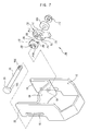
- the tilt adjusting unit includes a mounting bracket 10, a steering column 20, and first and second support brackets 31 and 32.
- the mounting bracket 10 is mounted to a predetermined portion of a vehicle body.
- the steering column 20 is provided to tilt up and down relative to the vehicle body.
- the first and second support brackets 31 and 32 extend from the mounting bracket 10 to be placed on left and right sides of the steering column 20, respectively.
- the first support bracket 31 is provided to the left side of the steering column 20, and the second support bracket 32 is provided to the right side of the steering column 20.
- a movable bracket 40 which is secured to the steering column 20 to tilt along with the steering column 20.
- a cover member 21 covers the steering column 20, and the movable bracket 40 is secured to the cover member 21 of the steering column 20 through, for example, a welding process.
- First and second support parts 41 extend from left and right edges of the movable bracket 40 to be supported by inner surfaces of the first and second support brackets 31 and 32, respectively.
- Each of the first and second support parts 41 has a through hole 43 at a predetermined portion thereof, and a guide slot 33 is formed along a tilting direction of the steering column 20 through each of the first and second support brackets 31 and 32 at a position corresponding to the through hole 43.
- the first and second support brackets 31 and 32 and the movable bracket 40 are connected to each other by a connection rod 50 which passes through the through holes 43 of the first and second support parts 41 and the guide slots 33 of the first and second support brackets 31 and 32.
- connection rod 50 moves up and down along the guide slots 33 while changing the angle of the steering column 20 which is secured to the movable bracket 40.
- First and second stoppers 51 and 52 are respectively provided on opposite ends of the connection rod 50 to prevent the first and second support brackets 31 and 32 from being removed from an outside the connection rod 50, thus preventing the movable bracket 40 from being removed from the first and second support brackets 31 and 32.
- the first stopper 51 is provided to a left side of the connection rod 50, and is fastened to a first end of the connection rod 50 in a screw-type fastening method.
- the second stopper 52 is integrally provided on a second end of the connection rod 50. To fasten the first stopper 51 to the first end of the connection rod 50 in the screw-type fastening method, the first stopper 51 has an internal threaded part 51a, and the connection rod 50 has an external threaded part 50a on the first end thereof.
- a locking unit 60 is provided at a predetermined position between the first stopper 51 and the first support bracket 31 to lock or unlock the movable bracket 40 to or from the first and second support brackets 31 and 32, thus locking the steering column 20 at an adjusted angle or releasing the steering column 20 from a locked position.
- the locking unit 60 includes a rotary unit 70 and inner and outer movable units 81 and 82.
- the rotary unit 70 is rotatably provided on a predetermined portion of the connection rod 50.
- the inner and outer movable units 81 and 82 are provided so that the inner and outer movable units 81 and 82 and the rotary unit 70 support each other, and the inner and outer movable units 81 and 82 move along the connection rod 50 as the rotary unit 70 rotates, thus locking or unlocking the movable bracket 40 to or from the first and second support brackets 31 and 32.
- a rotation restraining part 90 is provided on a predetermined portion of one of the rotary unit 70 and the inner and outer movable units 81 and 82 to prevent the rotary unit 70 from rotating when the movable bracket 40 is locked to the first and second support brackets 31 and 32.
- the inner and outer movable units 81 and 82 move along the connection rod 50 to lock the movable bracket 40 to the first and second support brackets 31 and 32. Further, when the movable bracket 40 is locked to the first and second support brackets 31 and 32, the rotation restraining part 90 prevents the rotary unit 70 from rotating, thus allowing a user to easily confirm whether the steering column 20 is locked at a desired angle or not.
- the rotary unit 70 includes a body 71 and a lever 72.
- the body 71 has at a central portion thereof a locking hole 71a so that the connection rod 50 passes through the locking hole 71 a.
- the lever 72 extends from the body 71 to a predetermined height.
- the inner and outer movable units 81 and 82 are provided on right and left sides of the rotary unit 70, respectively.
- the inner movable unit 81 is provided at a predetermined position inside the rotary unit 70
- the outer movable unit 82 is provided at a predetermined position outside the rotary unit 70.
- the inner and outer movable units 81 and 82 are provided to be symmetrical with each other relative to the rotary unit 70.
- the inner and outer movable units 81 and 82 respectively have locking holes 83 so that the connection rod 50 passes through the locking holes 83.
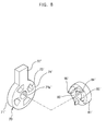
- a first cam face 85 is provided on each of facing surfaces of the inner and outer movable units 81 and 82 which face the rotary unit 70.
- the first cam face 85 has an inclined part 84 which is inclined along a circumferential direction of the first cam face 85.
- a second cam face 74 is provided on each of opposite surfaces of the rotary unit 70 which face the inner and outer movable units 81 and 82.
- the second cam face 74 has a pressing part 73 to press or release the inclined part 84 of the first cam face 85 according to a rotating direction of the rotary unit 70.
- the movable bracket 40 is in close contact with the first and second support brackets 31 and 32 to be locked to the first and second support brackets 31 and 32.
- the rotary unit 70 rotates in a reverse direction
- the inclined parts 84 are released from the pressing parts 73, and simultaneously, the first support bracket 31 is released from the locking unit 60. Thereby, the movable bracket 40 is unlocked from the first and second support brackets 31 and 32.
- first cam faces 85 may be provided on the opposite surfaces of the rotary unit 70 and the second cam faces 74 may be provided on the facing surfaces of the inner and outer movable units 81 and 82 which face the rotary unit 70, the inner and outer movable units 81 and 82 may move away from the rotary unit 70 by a rotation of the rotary unit 70.
- first cam faces 85 may be provided on the opposite surfaces of the rotary unit 70 and the second cam faces 74 may be provided on the facing surfaces of the inner and outer movable units 81 and 82 which face the rotary unit 70.
- the inclined part 84 may comprise a plurality of inclined parts and the pressing part 73 may comprise a plurality of pressing parts corresponding to the plurality of inclined parts, so as to allow the inner and outer movable units 81 and 82 to more stably and smoothly move.
- connection rod 50 and the inner and outer movable units 81 and 82 are provided so that the connection rod 50 and the inner and outer movable units 81 and 82 are prevented from rotating.
- a first rotation preventing projection 81a is provided on a surface of the inner movable unit 81 which is opposite to the first cam face 85, and the first rotation preventing projection 81a is supported by the first support bracket 31.
- a second rotation preventing projection 52a is provided on a predetermined portion of the second stopper 52 to be supported by the second support bracket 32.
- a third rotation preventing projection 82a is provided on a surface of the outer movable unit 82 which is opposite to the first cam face 85, and the third rotation preventing projection 82a is supported by the first stopper 51.
- the first, second, and third rotation preventing projections 81a, 52a, and 82a prevent the inner and outer movable units 81 and 82 and the connection rod 50 from rotating.
- the inner and outer movable units 81 and 82 rectilinearly reciprocate along the connection rod 50, but do not rotate.
- the first and second rotation preventing projections 81a and 52a are fitted into the guide slots 33 of the first and second support brackets 31 and 32, respectively, so that the first and second rotation preventing projections 81 a and 52a are supported by the first and second support brackets 31 and 32, respectively, without any mounting member.
- the first stopper 51 has a seat groove 51 b so that the third rotation preventing projection 82a is seated in the first stopper 51.
- the rotation restraining part 90 is provided to allow the user to easily confirm whether the steering column 20 is locked at the adjusted angle or not.
- the rotation restraining part 90 is provided at an edge of the inclined part 84 which is provided on the first cam face 85 to prevent the rotary unit 70 from rotating when the inner and outer movable units 81 and 82 move away from the rotary unit 70 to a maximum, thus allowing the user to easily confirm whether the steering column 20 is locked at the desired angle or not.
- the inclined part 84 has a shape of a depression which is depressed on the first cam face 85
- the pressing part 73 has a shape of a projection which is projected from the cam face 74.
- the rotation restraining part 90 is provided between the edge of the inclined part 84, which is adjacent to the second cam face 74, and the first cam face 85.
- first and second support brackets 31 and 32 and the movable bracket 40 are fitted over the connection rod 50 to be connected to each other, prior to assembling the first stopper 51 with the connection rod 50.
- the second rotation preventing projection 52a of the second stopper 52 is fitted into the guide slot 33 of the second support bracket 32.
- the inner movable unit 81 is fitted over the first end of the connection rod 50 which extends to an outside of the first support bracket 31, and the first rotation preventing projection 81 a of the inner movable unit 81 is fitted into the guide slot 33 of the first support bracket 31.
- the rotary unit 70 and the outer movable unit 82 are sequentially fitted over the connection rod 50.
- the first stopper 51 is fitted over the first end of the connection rod 50 at a position outside the outer movable unit 82 while the third rotation preventing projection 82a of the outer movable unit 82 is seated in the seat groove 51b of the first stopper 51.
- the pressing part 73 of the rotary unit 70 is placed to be in contact with a side surface of the inclined part 84 which is opposite to the rotation restraining part 90 so that the movable bracket 40 is released from the first and second support brackets 31 and 32.
- each of the pressing parts 73 provided on the second cam face 74 moves along each of the inclined parts 84 of the first cam face 85 until being stopped by the rotation restraining part 90 which is provided at the edge of each of the inclined parts 84. Further, the inner and outer movable units 81 and 82 move away from the rotary unit 70 in opposing directions to the maximum.
- the locking unit 60 which is provided between the first support bracket 31 and the first stopper 51, moves along the connection rod 50 toward the first support bracket 31 by a distance between the inner and outer movable units 81 and 82 which move away from the rotary unit 70 in opposing directions, and thereby press the first support bracket 31. Therefore, the first and second support brackets 31 and 32 come into close contact with the first and second support parts 41 of the movable bracket 40, respectively.
- the movable bracket 40 is locked to the first and second support brackets 31 and 32, and the steering column 40 which is secured to the movable bracket 40 is also locked.
- the tilt adjusting unit for steering columns is provided with two movable units. But, the steering column 20 may be locked using a locking unit 60' which has one movable unit.
- a tilt adjusting unit having one movable unit according to a second embodiment will be described in the following.
- the tilt adjusting unit according to the second embodiment remains the same as the tilt adjusting unit according to the first embodiment, except for a construction of the locking unit 60', those elements common to the first and second embodiments will not be described herein in detail.
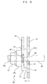
- the locking unit 60' is provided at a predetermined position between a first stopper 51' and the first support bracket 31.
- the locking unit 60' includes a rotary unit 70' and one movable unit 81'.
- the movable unit 81' is provided between the rotary unit 70' and the first support bracket 31.
- a bearing 100 is provided between the first stopper 51' and the rotary unit 70' to ensure a smooth rotation of the rotary unit 70'.
- the rotary unit 70' includes a body 71' which has at a central portion thereof a locking hole 71a' so that the connection rod 50 passes through the locking hole 71a'.
- a lever 72' extends from the body 71' to a predetermined height.
- the movable unit 81' has a locking hole 83' at a central portion thereof so that the connection rod 50 passes through the locking hole 83'.
- First and second cam faces 85' and 74' are provided on facing surfaces of the movable unit 81' and the rotary unit 70', respectively. In this case, the first cam face 85' has an inclined part 84', and the second cam face 74' has a pressing part 73'.
- first and second cam faces 85' and 74' may be respectively provided on the facing surfaces of the rotary unit 70' and the movable unit 81'.
- the inclined part 84' comprises a plurality of inclined parts
- the pressing part 73' comprises a plurality of pressing parts corresponding to the plurality of inclined parts, thus allowing the movable unit 81' to stably move.
- a rotation restraining part 90' is provided at an edge of each of the inclined parts 84' which are provided on the first cam face 85', thus preventing the rotary unit 70' from rotating when the steering column 20 is locked.
- each of the inclined parts 84' has a shape of a projection which is projected from the first cam face 85'
- each of the pressing parts 73' has a shape of a hole which is formed through the rotary unit 70' to receive the corresponding inclined part 84', thus pressing the inclined part 84' when the rotary unit 70' rotates.
- the rotation restraining part 90' extends from the edge of the inclined part 84', which is adjacent to the second cam face 74', into the pressing part 73'.
- each of the inclined parts 84' is placed in the corresponding pressing part 73'.
- each of the inclined parts 84' moves to an outside of the corresponding pressing part 73', so that the movable unit 81' moves away from the rotary unit 70'.
- an edge of each of the pressing parts 73' which has the shape of the hole is stopped by each of the rotation restraining parts 90' which extends into each of the pressing parts 73'.
- the movable unit 81' moves away from the rotary unit 70' to a maximum and thereby the movable bracket 40 is locked to the first and second support brackets 31 and 32.
- the rotary unit 70' does not rotate any more, thus allowing the user to easily confirm whether the steering column 20 is locked at the desired angle or not.
- each of the pressing parts 73' may have a shape of a depression which is depressed on the second cam face 74', without being limited to the shape of the hole according to the second embodiment.
- Each of the pressing parts 73' having the shape of the depression provides the same operational effect of the pressing parts 73' having the shape of the hole.
- the rotation restraining part 90' may be constructed to extend into each of the pressing parts 73' having the shape of the depression. The rotation restraining part 90' functions to restrict a rotation of the rotary unit 70' when the steering column 20 has been locked.
- the movable unit 81' and the connection rod 50 are prevented from rotating by a torque which is generated by a rotation of the rotary unit 70' when the locking unit 60' is operated, similarly to the tilt adjusting unit of the first embodiment.
- a first rotation preventing projection 81a' is provided on a surface of the movable unit 81' which is opposite to the first cam face 85', and the first rotation preventing projection 81a' is supported by the first support bracket 31.
- a second rotation preventing projection 52a is provided on a predetermined portion of the second stopper 52 to be supported by the second support bracket 32.
- the first and second rotation preventing projections 81a' and 52a prevent the movable unit 81' and the connection rod 50 from rotating.
- the movable unit 81' only rectilinearly reciprocates along the connection rod 50.
- the first and second rotation preventing projections 81a' and 52a are fitted into the guide slots 33 of the first and second support brackets 31 and 32, respectively, so that the first and second rotation preventing projections 81a' and 52a are supported by the first and second support brackets 31 and 32, respectively, without using any mounting member.
- first and second support brackets 31 and 32 and the movable bracket 40 are fitted over the connection rod 50 to be connected to each other, prior to assembling the first stopper 51' with the connection rod 50.
- the second rotation preventing projection 52a of the second stopper 52 is fitted into the guide slot 33 of the second support bracket 32.
- the movable unit 81' is fitted over the first end of the connection rod 50 which extends to an outside of the first support bracket 31, and the first rotation preventing projection 81a' of the movable unit 81' is fitted into the guide slot 33 of the first support bracket 31.
- the rotary unit 70' and the bearing 100 are sequentially fitted over the connection rod 50.
- the first stopper 51' is fitted over the first end of the connection rod 50 at a position outside the bearing 100.
- each of the inclined parts 84' of the movable unit 81' is placed in each of the pressing parts 73' of the rotary unit 70' having the shape of the hole so that the movable bracket 40 is unlocked from the first and second support brackets 31 and 32.
- each of the inclined parts 84' provided on the first cam face 85' moves out of each of the pressing parts 73' provided on the second cam face 74', and an edge of each of the pressing parts 73' having the shape of the hole is stopped by the rotation restraining part 90' which is provided at an edge of each of the inclined parts 84'.
- the movable unit 81' moves away from the rotary unit 70' to a maximum.
- the locking unit 60' which is provided between the first support bracket 31 and the first stopper 51', moves along the connection rod 50 toward the first support bracket 31 by a distance from the rotary unit 70' to the movable unit 81', and thereby press the first support bracket 31. Therefore, the first and second support brackets 31 and 32 come into close contact with the first and second support parts 41 of the movable bracket 40, respectively.
- the movable bracket 40 is locked to the first and second support brackets 31 and 32, and the steering column 40 which is secured to the movable bracket 40 is also locked.
- the tilt adjusting unit according to the second embodiment is provided with the bearing 100, thus allowing the rotary unit 70' to more smoothly rotate when the locking unit 60' is operated. Because the tilt adjusting unit according to the second embodiment has one movable unit 81', a width of the locking unit 60' is reduced and thereby a volume of the tilt adjusting unit is reduced.
- the operation of the locking unit 60, 60' of the tilt adjusting unit for steering columns according to the present invention is as follows. As the rotary unit 70, 70' rotates, the movable unit 81 and 82, 81' move along the connection rod 50 to lock the movable bracket 40 to the first and second support brackets 31 and 32. Further, when the movable bracket 40 is locked to the first and second support brackets 31 and 32, the rotation restraining part 90, 90' of the locking unit 60, 60' prevents the rotary unit 70, 70' from rotating, thus allowing the user to easily confirm whether the steering column 20 is locked at the adjusted angle or not.
- the locking unit 60, 60' is provided between the first stopper 51, 51' and the first support bracket 31.
- the locking unit 60, 60' may be provided between the second stopper 52 and the second support bracket 32, or between the first and second support brackets 31 and 32 and the movable bracket 40, or between the first and second support parts 41 of the movable bracket 40.
- the movable unit 81 and 82, 81' moves away from the rotary unit 70, 70' and thereby the movable bracket 40 is supported by the first and second support brackets 31 and 32.
- the present invention provides a tilt adjusting unit for steering columns, which has a locking unit.
- a movable unit moves along a connection rod to lock a movable bracket to support brackets.
- a rotation restraining part of the locking unit prevents the rotary unit from rotating, thus allowing a user to easily confirm whether a steering column is locked at a desired angle or not.
Landscapes
- Engineering & Computer Science (AREA)
- Chemical & Material Sciences (AREA)
- Combustion & Propulsion (AREA)
- Transportation (AREA)
- Mechanical Engineering (AREA)
- Steering Controls (AREA)
- Pivots And Pivotal Connections (AREA)
- Pinball Game Machines (AREA)
Abstract
Description
Claims (15)
- A tilt adjusting unit for steering columns, comprising:a support bracket mounted to a predetermined portion of a vehicle body;a steering column mounted to a predetermined portion of the vehicle body to tilt relative to the vehicle body;a movable bracket to tilt along with the steering column;a connection rod to connect the movable bracket to the support bracket;a guide slot formed on a predetermined portion of the support bracket along a tilting direction of the steering column, with the connection rod passing through the guide slot;a stopper provided at each of opposite ends of the connection rod to prevent the movable bracket from being removed from the support bracket; anda locking unit provided on a predetermined portion of the connection rod to lock or unlock the movable bracket to or from the support bracket, the locking unit comprising:a rotary unit rotatably provided on a predetermined portion of the connection rod;a movable unit provided on a predetermined portion of the connection rod so that the movable unit and the rotary unit support each other, the movable unit moving along the connection rod as the rotary unit rotates, thus locking or unlocking the movable bracket to or from the support bracket; anda rotation restraining part provided on a predetermined portion of either the rotary unit or the movable unit to prevent the rotary unit from rotating when the movable bracket is locked to the support bracket.
- The tilt adjusting unit according to claim 1, further comprising:a first cam face provided on one of facing surfaces of the rotary unit and the movable unit which face each other, the first cam face having an inclined part which is inclined along a circumferential direction of the first cam face; anda second cam face provided on a remaining one of the facing surfaces of the rotary unit and the movable unit which face each other, the second cam face having a pressing part to press or release the inclined part according to a rotating direction of the rotary unit.
- The tilt adjusting unit according to claim 2, wherein the rotation restraining part is provided at an edge of the inclined part to stop the pressing part.
- The tilt adjusting unit according to claim 3, wherein the inclined part has a shape of a depression which is depressed on the first cam face, the pressing part has a shape of a projection which is projected from the second cam face, and the rotation restraining part is provided between the edge of the inclined part, which is adjacent to the second cam face, and the first cam face.
- The tilt adjusting unit according to claim 3, wherein the inclined part has a shape of a projection which is projected from the first cam face, the pressing part is provided to receive the inclined part therein, and the rotation restraining part extends from the edge of the inclined part, which is adjacent to the second cam face, into the pressing part.
- The tilt adjusting unit according to claim 2, wherein the inclined part comprises a plurality of inclined parts, and the pressing part comprises a plurality of pressing parts corresponding to the plurality of inclined parts.
- The tilt adjusting unit according to claim 2, wherein the movable unit and the connection rod are provided so that the movable unit and the connection rod are prevented from rotating.
- The tilt adjusting unit according to claim 2, wherein the movable unit comprises a pair of movable units provided on opposite sides of the rotary unit, the pair of movable units comprising:an inner movable unit provided at a predetermined position inside the rotary unit; andan outer movable unit provided at a predetermined position outside the rotary unit.
- The tilt adjusting unit according to claim 8, wherein
the support bracket comprises first and second support brackets which are provided on opposite sides of the steering column, respectively, with a first rotation preventing projection being provided at a predetermined portion of the inner movable unit to be supported by the first support bracket, and a second rotation preventing projection being provided at a predetermined portion of the stopper to be supported by the second support bracket, thus preventing the inner movable unit and the connection rod from rotating,
the movable bracket is provided at a predetermined position between the first and second support brackets,
the stopper comprises:a first stopper which is provided at a predetermined position adjacent to the first support bracket, with a third rotation preventing projection being provided at a predetermined portion of the outer movable unit to be mounted to the first stopper, thus preventing the outer movable unit from rotating; anda second stopper which is provided at a predetermined position adjacent to the second support bracket, with the second rotation preventing projection being provided at a predetermined portion of the second stopper, andthe locking unit is provided at a predetermined position between the first stopper and the first support bracket. - The tilt adjusting unit according to claim 9, wherein the first and second rotation preventing projections are respectively fitted into the guide slots of the first and second support brackets, and the first stopper has at a predetermined portion thereof a seat groove so that the third rotation preventing projection is seated in the seat groove.
- The tilt adjusting unit according to claim 2, wherein the movable unit is provided between the rotary unit and the support bracket.
- The tilt adjusting unit according to claim 11, wherein
the support bracket comprises first and second support brackets which are provided on opposite sides of the steering column, respectively, with a first rotation preventing projection being provided at a predetermined portion of the inner movable unit to be supported by the first support bracket, and a second rotation preventing projection being provided at a predetermined portion of the stopper to be supported by the second support bracket, thus preventing the movable unit and the connection rod from rotating,
the movable bracket is provided at a predetermined position between the first and second support brackets,
the stopper comprises:a first stopper which is provided at a predetermined position adjacent to the first support bracket; anda second stopper which is provided at a predetermined position adjacent to the second support bracket, with the second rotation preventing projection being provided at a predetermined portion of the second stopper, andthe locking unit is provided at a predetermined position between the first stopper and the first support bracket. - The tilt adjusting unit according to claim 12, wherein the first and second rotation preventing projections are respectively fitted into the guide slots of the first and second support brackets.
- The tilt adjusting unit according to claim 12, further comprising a bearing provided at a predetermined position between the rotary unit and the first stopper.
- The tilt adjusting unit according to claim 1, further comprising a lever provided on a predetermined portion of the rotary unit.
Applications Claiming Priority (6)
| Application Number | Priority Date | Filing Date | Title |
|---|---|---|---|
| KR20030000529 | 2003-01-06 | ||
| KR2003000530 | 2003-01-06 | ||
| KR20030000530 | 2003-01-06 | ||
| KR20030000528 | 2003-01-06 | ||
| KR2003000529 | 2003-01-06 | ||
| KR2003000528 | 2003-01-06 |
Publications (3)
| Publication Number | Publication Date |
|---|---|
| EP1435316A2 true EP1435316A2 (en) | 2004-07-07 |
| EP1435316A3 EP1435316A3 (en) | 2004-11-17 |
| EP1435316B1 EP1435316B1 (en) | 2006-08-02 |
Family
ID=32512144
Family Applications (2)
| Application Number | Title | Priority Date | Filing Date |
|---|---|---|---|
| EP03257766A Expired - Lifetime EP1435317B1 (en) | 2003-01-06 | 2003-12-10 | Tilt adjusting for steering columns |
| EP03257765A Expired - Lifetime EP1435316B1 (en) | 2003-01-06 | 2003-12-10 | Tilt adjusting unit for steering columns |
Family Applications Before (1)
| Application Number | Title | Priority Date | Filing Date |
|---|---|---|---|
| EP03257766A Expired - Lifetime EP1435317B1 (en) | 2003-01-06 | 2003-12-10 | Tilt adjusting for steering columns |
Country Status (5)
| Country | Link |
|---|---|
| US (2) | US7267025B2 (en) |
| EP (2) | EP1435317B1 (en) |
| JP (2) | JP2004210265A (en) |
| CN (2) | CN1299943C (en) |
| DE (2) | DE60307218T2 (en) |
Cited By (2)
| Publication number | Priority date | Publication date | Assignee | Title |
|---|---|---|---|---|
| DE102006054455A1 (en) * | 2006-11-16 | 2008-05-21 | Zf Lenksysteme Nacam Gmbh | Locking device for adjustable steering column of motor vehicle, has linking device formed by sloping level on front side of clamping section and by slide that is formed as single piece for actuating lever in borehole area of actuating lever |
| CN104670298A (en) * | 2015-02-11 | 2015-06-03 | 浙江万达汽车方向机有限公司 | Adjustable pipe string with slotted clamping structure |
Families Citing this family (76)
| Publication number | Priority date | Publication date | Assignee | Title |
|---|---|---|---|---|
| TWI289236B (en) * | 2003-12-31 | 2007-11-01 | Hon Hai Prec Ind Co Ltd | Electrochromic display device |
| US20050151361A1 (en) * | 2004-01-14 | 2005-07-14 | Mazda Motor Corporation | Steering support structure of vehicle |
| KR101027034B1 (en) * | 2005-01-18 | 2011-04-11 | 주식회사 만도 | Tilting device for vehicle steering column |
| JP4247996B2 (en) * | 2005-03-18 | 2009-04-02 | 株式会社山田製作所 | Steering device fixing device |
| FR2886605B1 (en) * | 2005-06-02 | 2009-03-06 | Timken Co | STEERING COLUMN LOCKING MODULE AND CORRESPONDING STEERING COLUMN |
| WO2007026118A2 (en) * | 2005-09-01 | 2007-03-08 | Trw Limited | A steering column assembly |
| GB0517780D0 (en) * | 2005-09-01 | 2005-10-12 | Trw Lucasvarity Electric Steer | A steering column assembly |
| GB0525850D0 (en) * | 2005-09-01 | 2006-02-01 | Trw Lucasvarity Electric Steer | A Steering Column Assembly |
| JP4622756B2 (en) * | 2005-09-08 | 2011-02-02 | 日本精工株式会社 | Steering wheel position adjusting device and manufacturing method of friction plate unit for the position adjusting device |
| KR100738378B1 (en) * | 2005-10-24 | 2007-07-12 | 주식회사 만도 | Tilt lever and steering column of automobile with same |
| JP5017870B2 (en) * | 2006-02-01 | 2012-09-05 | 日本精工株式会社 | Steering device |
| KR100746663B1 (en) * | 2006-05-09 | 2007-08-06 | 주식회사 만도 | Tilt and Telescope Steering |
| JP5070795B2 (en) | 2006-10-19 | 2012-11-14 | 日本精工株式会社 | Steering wheel position adjustment device |
| DE102007053672A1 (en) * | 2007-11-10 | 2009-05-20 | Daimler Ag | Steering column assembly for motor vehicles |
| KR100992695B1 (en) | 2007-11-13 | 2010-11-05 | 기아자동차주식회사 | Locking device structure of tilting and telescopic steering column |
| JP5098686B2 (en) * | 2008-02-18 | 2012-12-12 | 日本精工株式会社 | Steering device |
| EP2105369A2 (en) * | 2008-03-25 | 2009-09-30 | NSK Ltd. | Steering apparatus |
| ATE524367T1 (en) * | 2008-05-16 | 2011-09-15 | Zf Systemes De Direction Nacam Sas | DEVICE FOR ADJUSTING THE POSITION OF A STEERING COLUMN IN A MOTOR VEHICLE |
| DE102008024405A1 (en) * | 2008-05-20 | 2010-01-28 | Thyssenkrupp Presta Ag | Clamping bolt for a locking device of an adjustable steering column |
| KR101170454B1 (en) | 2008-06-03 | 2012-08-07 | 한국델파이주식회사 | Apparatus for adjusting of steering column of vehicle |
| JP5304046B2 (en) * | 2008-06-13 | 2013-10-02 | 日本精工株式会社 | Steering device |
| FR2933058B1 (en) * | 2008-06-30 | 2010-08-27 | Zf Systemes De Direction Nacam Sas | LOCKING ASSISTANCE DEVICE FOR A STEERING COLUMN |
| DE102008045143B4 (en) * | 2008-09-01 | 2012-05-24 | Thyssenkrupp Presta Ag | Adjustable steering column for a motor vehicle |
| US20110088501A1 (en) * | 2009-10-20 | 2011-04-21 | Mando Corporation | Steering column for vehicle |
| DE102010001847A1 (en) * | 2010-02-11 | 2011-08-11 | Brose Fahrzeugteile GmbH & Co. Kommanditgesellschaft, Coburg, 96450 | Spindle gear with reinforcement |
| EP2617624B1 (en) * | 2010-09-14 | 2019-08-28 | NSK Ltd. | Steering device |
| JP5338922B2 (en) * | 2010-09-14 | 2013-11-13 | 日本精工株式会社 | Steering device |
| US8641094B2 (en) * | 2010-11-23 | 2014-02-04 | Steering Solutions Ip Holding Corporation | Steering column telescope adjustment stop |
| US8523227B2 (en) | 2010-12-13 | 2013-09-03 | Caterpillar Inc. | Single point friction lock for tilt and telescope adjustment of steering columns |
| JP5614290B2 (en) * | 2011-01-06 | 2014-10-29 | 株式会社ジェイテクト | Steering device |
| JP5603783B2 (en) * | 2011-01-06 | 2014-10-08 | 株式会社ジェイテクト | Steering device |
| DE102011000319B3 (en) | 2011-01-25 | 2012-05-24 | Thyssenkrupp Presta Ag | Locking device for locking a steering shaft bearing unit |
| EP2692610B1 (en) * | 2011-03-31 | 2016-08-24 | NSK Ltd. | Steering column device |
| JP5723226B2 (en) * | 2011-06-07 | 2015-05-27 | 株式会社山田製作所 | Steering device |
| JP5447556B2 (en) * | 2011-06-15 | 2014-03-19 | 日本精工株式会社 | Steering device |
| JP5966290B2 (en) * | 2011-09-20 | 2016-08-10 | 日本精工株式会社 | Steering device |
| JP5891876B2 (en) * | 2012-03-19 | 2016-03-23 | 日本精工株式会社 | Steering device |
| JP5991516B2 (en) * | 2012-06-12 | 2016-09-14 | 株式会社ジェイテクト | Steering column device |
| EP2871113B1 (en) * | 2012-07-04 | 2019-01-09 | NSK Ltd. | Position adjustment device for steering wheel |
| JP6094177B2 (en) * | 2012-08-09 | 2017-03-15 | 日本精工株式会社 | Steering wheel position adjustment device |
| JP5929616B2 (en) * | 2012-08-10 | 2016-06-08 | 日本精工株式会社 | Steering wheel position adjustment device |
| KR101585421B1 (en) * | 2012-09-18 | 2016-01-15 | 주식회사 만도 | Steering Apparatus for Vehicle |
| EP2915719B1 (en) * | 2012-11-02 | 2018-07-11 | NSK Ltd. | Tilt-type steering device |
| JP6102205B2 (en) * | 2012-11-19 | 2017-03-29 | 日本精工株式会社 | Steering wheel position adjustment device |
| EP2927091B1 (en) * | 2012-11-28 | 2018-01-03 | NSK Ltd. | Steering wheel position adjustment device |
| DE102014201127B4 (en) | 2013-03-07 | 2022-02-03 | Ford Global Technologies, Llc | Side-tilting, multi-track vehicle |
| DE102014201670A1 (en) | 2013-03-07 | 2014-09-11 | Ford Global Technologies, Llc | Sideways inclinable, multi-lane vehicle |
| DE102014201632B4 (en) | 2013-03-07 | 2021-09-02 | Ford Global Technologies, Llc | Laterally tiltable, multi-lane vehicle |
| DE102014201668B4 (en) | 2013-03-07 | 2021-09-02 | Ford Global Technologies, Llc | Laterally tiltable, multi-lane vehicle |
| DE102014201630B4 (en) | 2013-03-07 | 2021-09-02 | Ford Global Technologies, Llc | Laterally tiltable, multi-lane vehicle |
| JP6103303B2 (en) * | 2013-07-05 | 2017-03-29 | 株式会社ジェイテクト | Steering device |
| US9505425B2 (en) * | 2013-09-30 | 2016-11-29 | Nsk Ltd. | Position adjustment device of steering wheel |
| WO2015104913A1 (en) * | 2014-01-07 | 2015-07-16 | 日本精工株式会社 | Position adjustment device for steering wheel |
| JP6192565B2 (en) * | 2014-02-21 | 2017-09-06 | 富士機工株式会社 | Steering column device |
| DE102014217246B3 (en) | 2014-08-29 | 2015-12-24 | Ford Global Technologies, Llc | Stabilization arrangement for a tilting chassis of a vehicle |
| DE102014217386B4 (en) | 2014-09-01 | 2024-11-14 | Ford Global Technologies, Llc | Method for operating a tilting chassis for a non-rail vehicle |
| CN104228928B (en) * | 2014-09-03 | 2018-07-31 | 青岛即东汽车零部件有限公司 | A kind of steering column and adjustment mechanism assembly of novel pneumatic auto lock |
| US10076939B2 (en) | 2014-11-26 | 2018-09-18 | Ford Global Technologies, Llc | Suspension systems for laterally tiltable multitrack vehicles |
| US10023019B2 (en) | 2015-02-24 | 2018-07-17 | Ford Global Technologies, Llc | Rear suspension systems with rotary devices for laterally tiltable multitrack vehicles |
| US9925843B2 (en) | 2015-02-24 | 2018-03-27 | Ford Global Technologies, Llc | Rear suspension systems for laterally tiltable multitrack vehicles |
| CN106314523B (en) * | 2015-06-17 | 2018-09-11 | 广州汽车集团股份有限公司 | Steering column regulating mechanism |
| DE102015112086B4 (en) * | 2015-07-24 | 2022-10-20 | Robert Bosch Automotive Steering Gmbh | DEVICE FOR ADJUSTING A STEERING COLUMN OF A MOTOR VEHICLE AND STEERING SYSTEM |
| JP2017047826A (en) * | 2015-09-03 | 2017-03-09 | 株式会社ジェイテクト | Steering device |
| CN107848560B (en) * | 2015-09-29 | 2020-03-27 | 日本精工株式会社 | Position adjusting device for steering wheel |
| JP6323621B2 (en) * | 2015-10-02 | 2018-05-16 | 日本精工株式会社 | Adjusting lever assembly and steering wheel position adjusting device |
| EP3395647B1 (en) * | 2016-02-04 | 2020-10-21 | NSK Ltd. | Steering apparatus |
| JP6098745B2 (en) * | 2016-02-18 | 2017-03-22 | 日本精工株式会社 | Steering device |
| US9849905B2 (en) * | 2016-03-09 | 2017-12-26 | Steering Solutions Ip Holding Corporation | Adjustable steering column assembly |
| JP6689692B2 (en) * | 2016-07-12 | 2020-04-28 | 株式会社ジェイテクト | Tightening device and steering device |
| US9758188B1 (en) * | 2016-08-01 | 2017-09-12 | Steering Solutions Ip Holding Corporation | Steering column assembly |
| JP6774908B2 (en) * | 2017-06-14 | 2020-10-28 | 株式会社ジェイテクト | Steering device |
| US10494012B2 (en) * | 2017-09-22 | 2019-12-03 | Steering Solutions Ip Holding Corporation | Travel control system for cam assembly |
| US10858032B2 (en) * | 2018-11-29 | 2020-12-08 | Steering Solutions Ip Holding Corporation | Clamp load adjustment assembly for steering column |
| US11279393B2 (en) * | 2020-04-29 | 2022-03-22 | Steering Solutions Ip Holding Corporation | Inner cam assembly for steering rake adjustment assembly |
| CN116946239A (en) * | 2022-04-13 | 2023-10-27 | 浙江春风动力股份有限公司 | All-terrain vehicle |
| KR20250160749A (en) * | 2024-05-07 | 2025-11-14 | 에이치엘만도 주식회사 | Steering apparatus for vehicle |
Family Cites Families (20)
| Publication number | Priority date | Publication date | Assignee | Title |
|---|---|---|---|---|
| GB2092967A (en) * | 1981-02-13 | 1982-08-25 | Ford Motor Co | Steering column assembly |
| FR2671040A1 (en) * | 1990-12-28 | 1992-07-03 | Ecia Equip Composants Ind Auto | LOCKING DEVICE IN THE POSITION OF AN ADJUSTABLE STEERING COLUMN OF A MOTOR VEHICLE. |
| US5722299A (en) * | 1994-06-30 | 1998-03-03 | Fuji Kiko Co., Ltd. | Adjustable steering column assembly for a vehicle |
| DE19506210C1 (en) * | 1995-02-23 | 1996-06-27 | Lemfoerder Metallwaren Ag | Clamping device for adjustable steering column in vehicles |
| FR2737172B1 (en) * | 1995-07-26 | 1997-10-10 | Nacam | GUIDANCE AND LOCKING SYSTEM FOR STEERING COLUMN OF MOTOR VEHICLES |
| GB2306629A (en) * | 1995-10-28 | 1997-05-07 | Nastech Europ Ltd | Adjustable vehicle steering column assembly |
| DE19640196C1 (en) * | 1996-09-30 | 1998-04-23 | Schaeffler Waelzlager Ohg | Clamping device for a steering column |
| FR2761036B1 (en) * | 1997-03-19 | 1999-06-04 | Ecia Equip Composants Ind Auto | POSITION ADJUSTABLE STEERING COLUMN ASSEMBLY, PARTICULARLY FOR MOTOR VEHICLE |
| GB2352695B (en) * | 1998-09-25 | 2002-10-16 | Douglas Autotech Corp | Steering wheel impact positioning system |
| SE521827C2 (en) * | 1998-11-27 | 2003-12-09 | Volvo Personvagnar Ab | Arrangements for steering |
| FR2802167B1 (en) * | 1999-12-10 | 2002-03-01 | Ecia Equip Composants Ind Auto | LOCKING DEVICE IN THE POSITION OF AN ADJUSTABLE STEERING COLUMN, PARTICULARLY FOR A MOTOR VEHICLE AND COLUMN ASSEMBLY COMPRISING SUCH A DEVICE |
| WO2001083284A1 (en) * | 2000-05-02 | 2001-11-08 | Douglas Autotech Corporation | Steering column support assembly |
| EP1180466B1 (en) * | 2000-08-11 | 2005-02-09 | Koyo Seiko Co., Ltd. | Tilt adjustable steering apparatus |
| DE10039794A1 (en) * | 2000-08-16 | 2002-02-28 | Daimler Chrysler Ag | Position adjustment device for a steering column |
| US6474189B1 (en) * | 2000-10-26 | 2002-11-05 | Trw Inc. | Apparatus for mounting a foot pedal and a steering column to a vehicle |
| GB2375809B (en) * | 2001-05-23 | 2005-02-23 | Nsk Steering Sys Europ Ltd | Operating lever |
| JP2003118595A (en) * | 2001-08-06 | 2003-04-23 | Nsk Ltd | VEHICLE STEERING DEVICE AND ITS MANUFACTURING METHOD |
| JP3906084B2 (en) | 2002-01-25 | 2007-04-18 | 株式会社ジェイテクト | Tilt steering device |
| US7010996B2 (en) * | 2002-03-08 | 2006-03-14 | Timken Us Corporation | Steering column clamping device |
| US6792824B2 (en) * | 2002-08-24 | 2004-09-21 | Daimlerchrysler Corporation | Tilt-telescope steering column |
-
2003
- 2003-12-10 EP EP03257766A patent/EP1435317B1/en not_active Expired - Lifetime
- 2003-12-10 EP EP03257765A patent/EP1435316B1/en not_active Expired - Lifetime
- 2003-12-10 DE DE60307218T patent/DE60307218T2/en not_active Expired - Lifetime
- 2003-12-10 DE DE60308805T patent/DE60308805T2/en not_active Expired - Lifetime
- 2003-12-19 JP JP2003423249A patent/JP2004210265A/en active Pending
- 2003-12-19 JP JP2003423231A patent/JP3810406B2/en not_active Expired - Fee Related
- 2003-12-23 US US10/746,593 patent/US7267025B2/en not_active Expired - Lifetime
- 2003-12-23 US US10/746,594 patent/US20040134301A1/en not_active Abandoned
- 2003-12-30 CN CNB2003101245154A patent/CN1299943C/en not_active Expired - Fee Related
- 2003-12-30 CN CNB2003101220814A patent/CN1308176C/en not_active Expired - Fee Related
Cited By (2)
| Publication number | Priority date | Publication date | Assignee | Title |
|---|---|---|---|---|
| DE102006054455A1 (en) * | 2006-11-16 | 2008-05-21 | Zf Lenksysteme Nacam Gmbh | Locking device for adjustable steering column of motor vehicle, has linking device formed by sloping level on front side of clamping section and by slide that is formed as single piece for actuating lever in borehole area of actuating lever |
| CN104670298A (en) * | 2015-02-11 | 2015-06-03 | 浙江万达汽车方向机有限公司 | Adjustable pipe string with slotted clamping structure |
Also Published As
| Publication number | Publication date |
|---|---|
| CN1308176C (en) | 2007-04-04 |
| JP2004210265A (en) | 2004-07-29 |
| EP1435316B1 (en) | 2006-08-02 |
| EP1435316A3 (en) | 2004-11-17 |
| CN1521075A (en) | 2004-08-18 |
| DE60307218D1 (en) | 2006-09-14 |
| EP1435317B1 (en) | 2006-10-04 |
| DE60308805D1 (en) | 2006-11-16 |
| US20040134301A1 (en) | 2004-07-15 |
| EP1435317A3 (en) | 2004-11-17 |
| EP1435317A2 (en) | 2004-07-07 |
| JP2004210264A (en) | 2004-07-29 |
| DE60307218T2 (en) | 2007-10-25 |
| CN1521076A (en) | 2004-08-18 |
| US20040134302A1 (en) | 2004-07-15 |
| JP3810406B2 (en) | 2006-08-16 |
| CN1299943C (en) | 2007-02-14 |
| DE60308805T2 (en) | 2007-08-23 |
| US7267025B2 (en) | 2007-09-11 |
Similar Documents
| Publication | Publication Date | Title |
|---|---|---|
| US7267025B2 (en) | Tilt adjusting unit for steering columns | |
| EP1180466B1 (en) | Tilt adjustable steering apparatus | |
| US7861615B2 (en) | Adjustable steering column assembly | |
| US6908156B1 (en) | Round recliner for vehicle | |
| US7685903B2 (en) | Dual on-center column lock mechanism | |
| US8327733B2 (en) | Pivoting locking device for an adjustable steering column | |
| US5531317A (en) | Tilt-type steering column device | |
| US20050199087A1 (en) | Single-motor power telescope and tilt steering column | |
| US6234040B1 (en) | Rotating, traveling energy absorber for steering column | |
| US6237439B1 (en) | Single release lever for steering column tilt and telescope | |
| JPH0471980A (en) | Pedal for bicycle | |
| JP3782928B2 (en) | Tilt steering device | |
| JP2022114814A (en) | steering device | |
| JP2002059851A (en) | Tilt steering device | |
| US7509887B2 (en) | Steering column assembly having single lever tilt and telescope adjustment | |
| JP2008055983A (en) | Movable steering device | |
| US7083198B2 (en) | Tilt steering apparatus for vehicle | |
| KR100530030B1 (en) | Tilt steering apparatus for vehicle | |
| JP2005014681A (en) | Steering column device for vehicle | |
| JP4470302B2 (en) | Vehicle steering device | |
| JP3834186B2 (en) | Door mirror rotation regulation structure | |
| JP2002104205A (en) | Vehicle steering system | |
| JP2008030542A (en) | Position adjustment type steering device | |
| KR100599486B1 (en) | Cam type tilt tracking device of vehicle tilt column | |
| JP4305626B2 (en) | Steering tilt device |
Legal Events
| Date | Code | Title | Description |
|---|---|---|---|
| PUAI | Public reference made under article 153(3) epc to a published international application that has entered the european phase |
Free format text: ORIGINAL CODE: 0009012 |
|
| 17P | Request for examination filed |
Effective date: 20031222 |
|
| AK | Designated contracting states |
Kind code of ref document: A2 Designated state(s): AT BE BG CH CY CZ DE DK EE ES FI FR GB GR HU IE IT LI LU MC NL PT RO SE SI SK TR |
|
| AX | Request for extension of the european patent |
Extension state: AL LT LV MK |
|
| PUAL | Search report despatched |
Free format text: ORIGINAL CODE: 0009013 |
|
| AK | Designated contracting states |
Kind code of ref document: A3 Designated state(s): AT BE BG CH CY CZ DE DK EE ES FI FR GB GR HU IE IT LI LU MC NL PT RO SE SI SK TR |
|
| AX | Request for extension of the european patent |
Extension state: AL LT LV MK |
|
| RIC1 | Information provided on ipc code assigned before grant |
Ipc: 7B 62D 1/18 B Ipc: 7B 62D 1/184 A |
|
| AKX | Designation fees paid |
Designated state(s): DE GB |
|
| GRAP | Despatch of communication of intention to grant a patent |
Free format text: ORIGINAL CODE: EPIDOSNIGR1 |
|
| GRAS | Grant fee paid |
Free format text: ORIGINAL CODE: EPIDOSNIGR3 |
|
| GRAA | (expected) grant |
Free format text: ORIGINAL CODE: 0009210 |
|
| AK | Designated contracting states |
Kind code of ref document: B1 Designated state(s): DE GB |
|
| REG | Reference to a national code |
Ref country code: GB Ref legal event code: FG4D |
|
| REF | Corresponds to: |
Ref document number: 60307218 Country of ref document: DE Date of ref document: 20060914 Kind code of ref document: P |
|
| PLBE | No opposition filed within time limit |
Free format text: ORIGINAL CODE: 0009261 |
|
| STAA | Information on the status of an ep patent application or granted ep patent |
Free format text: STATUS: NO OPPOSITION FILED WITHIN TIME LIMIT |
|
| 26N | No opposition filed |
Effective date: 20070503 |
|
| PGFP | Annual fee paid to national office [announced via postgrant information from national office to epo] |
Ref country code: DE Payment date: 20180820 Year of fee payment: 16 |
|
| PGFP | Annual fee paid to national office [announced via postgrant information from national office to epo] |
Ref country code: GB Payment date: 20191008 Year of fee payment: 17 |
|
| REG | Reference to a national code |
Ref country code: DE Ref legal event code: R119 Ref document number: 60307218 Country of ref document: DE |
|
| PG25 | Lapsed in a contracting state [announced via postgrant information from national office to epo] |
Ref country code: DE Free format text: LAPSE BECAUSE OF NON-PAYMENT OF DUE FEES Effective date: 20200701 |
|
| GBPC | Gb: european patent ceased through non-payment of renewal fee |
Effective date: 20201210 |
|
| PG25 | Lapsed in a contracting state [announced via postgrant information from national office to epo] |
Ref country code: GB Free format text: LAPSE BECAUSE OF NON-PAYMENT OF DUE FEES Effective date: 20201210 |