EP1435304A1 - Coupling and tensioning device for snow chains - Google Patents
Coupling and tensioning device for snow chains Download PDFInfo
- Publication number
- EP1435304A1 EP1435304A1 EP02425812A EP02425812A EP1435304A1 EP 1435304 A1 EP1435304 A1 EP 1435304A1 EP 02425812 A EP02425812 A EP 02425812A EP 02425812 A EP02425812 A EP 02425812A EP 1435304 A1 EP1435304 A1 EP 1435304A1
- Authority
- EP
- European Patent Office
- Prior art keywords
- coupling
- tensioning device
- main body
- lever
- return block
- Prior art date
- Legal status (The legal status is an assumption and is not a legal conclusion. Google has not performed a legal analysis and makes no representation as to the accuracy of the status listed.)
- Granted
Links
- 230000008878 coupling Effects 0.000 title claims abstract description 69
- 238000010168 coupling process Methods 0.000 title claims abstract description 69
- 238000005859 coupling reaction Methods 0.000 title claims abstract description 69
- ZZUFCTLCJUWOSV-UHFFFAOYSA-N furosemide Chemical group C1=C(Cl)C(S(=O)(=O)N)=CC(C(O)=O)=C1NCC1=CC=CO1 ZZUFCTLCJUWOSV-UHFFFAOYSA-N 0.000 description 5
- 230000006866 deterioration Effects 0.000 description 3
- 235000001674 Agaricus brunnescens Nutrition 0.000 description 1
- 239000010426 asphalt Substances 0.000 description 1
- 230000001419 dependent effect Effects 0.000 description 1
- 238000001746 injection moulding Methods 0.000 description 1
- 239000002184 metal Substances 0.000 description 1
- 238000012986 modification Methods 0.000 description 1
- 230000004048 modification Effects 0.000 description 1
- 230000000284 resting effect Effects 0.000 description 1
Images


Classifications
-
- B—PERFORMING OPERATIONS; TRANSPORTING
- B60—VEHICLES IN GENERAL
- B60C—VEHICLE TYRES; TYRE INFLATION; TYRE CHANGING; CONNECTING VALVES TO INFLATABLE ELASTIC BODIES IN GENERAL; DEVICES OR ARRANGEMENTS RELATED TO TYRES
- B60C27/00—Non-skid devices temporarily attachable to resilient tyres or resiliently-tyred wheels
- B60C27/02—Non-skid devices temporarily attachable to resilient tyres or resiliently-tyred wheels extending over restricted arcuate part of tread
- B60C27/0238—Non-skid devices temporarily attachable to resilient tyres or resiliently-tyred wheels extending over restricted arcuate part of tread provided with tensioning means
Definitions
- the present invention relates to a coupling and tensioning device for snow chains or anti-skid devices designed to be mounted on the tyres of vehicles.
- Said coupling and tensioning device is particularly suitable to be applied to lengths of emergency snow chains, commonly called strap-on chains and generally used in wheels of large vehicles, such as trucks and the like.
- Snow chains normally mounted on the driving wheels of the vehicle, by biting into the snow and/or ice deposited on the road surface, increase the traction on the tread, permitting good holding by the tyres of the vehicle.
- a strap-on chain generally comprises three lengths of chain disposed parallel, the ends of which are connected to two flanges, so that the lengths of chain abut on the tread of the tyre and the flanges abut respectively on the inside and outside walls of the tyre.
- a terminal length of chain is connected to the flange disposed on the inside wall of the tyre and is passed through one of the holes in the wheel rim to hook on to a coupling and tensioning device connected to the flange disposed on the outside wall of the tyre.
- the coupling and tensioning devices generally comprise a tie rod, which is hooked at one end and threaded at the other.
- the threaded end of the tie rod is connected by means of a nut to a plate in turn connected to the outer flange.
- the user hooks a link of the terminal length of chain to the hook of the tie rod and then, by means of a special tool such as a spanner, tightens the nut to tension the strap-on chain.
- the connecting plate between the tie rod and the outer flange is made of metal and since it abuts against the edge of the wheel rim, can cause damage or deterioration thereof.
- the object of the present invention is to overcome the drawbacks of the prior art, providing a coupling and tensioning device for snow chains that is safe, efficient and such as to allow perfect tensioning of the snow chains, avoiding any accidental slackening.
- Another object of the present invention is to provide a coupling and tensioning device for snow chains that is practical and easy to use for the user and at the same time allows extremely rapid mounting of the snow chains.
- Another object of the present invention is to provide a coupling and tensioning device for snow chains that is able to avoid damage to and deterioration of the wheel rim of the vehicle whereon it is mounted.
- Yet another object of the present invention is to provide a coupling and tensioning device for snow chains that is cheap and simple to make.
- the coupling and tensioning device according to the invention is suitable to be applied to chains comprising an outer flange able to be placed on the outside wall of the tyre, an inner flange able to be positioned on the inside wall of the tyre, said flanges being joined by variously composed elements creating the traction on the tread.
- the coupling and tensioning device comprises first coupling means designed to couple with the outer flange and second coupling means designed to couple with a terminal portion connected to the inner flange.
- the coupling and tensioning device comprises:
- the body of the coupling and tensioning device can be formed by means of plastic shells, avoiding damaging the wheel rim.
- the coupling and tensioning device 100 comprises a main body 1, fist coupling means 3 mounted at one end of the body 1, an anti-return block 5 slidably mounted in the body 1, second coupling means 7 mounted inside the anti-return block 5 and lever operating means 8 connected to the body 1 to move the anti-return block 5.
- the body 1 is a substantially L-shaped box-type body, with a top part and a larger bottom part. With reference to the figures, the body 1 has two side walls (only one visible in the figures), a front wall 11 destined to face outwards and a rear wall (not visible in the figure) destined to face towards the vehicle wheel.
- the slot 13 communicates with a widened central seat 14 rectangular in section.
- a transverse, rectilinear through slot 19 which runs from one side wall 10 to the other side wall of the body 1 passing through the central seat 14, is provided in the bottom part of the body 1.
- a threaded hole 22 to receive a bolt 16 for mounting a coupling plate 15 is provided on the front surface 11 of the top part of the body 1.
- the coupling plate 15 is bent substantially in a Z shape, so that it protrudes forward from the front surface 11.
- Two slots 17 parallel to each other are formed at the top end of the body 1.
- the slots 17 are passed through by a transverse through hole 18, which pass through the body 1 from one side wall to the other.
- the first coupling means 3 comprise a rectangular plate 30, to which two "ring rivets" 31 are fixed.
- a hook 32 which protrudes in the opposite direction with respect to the ring rivets 31, is hinged in a central position of the plate 30. Hook 32 can rotate around its axis, which is at right angle to the plane of the plate 30.
- the two ring rivets 31 are so disposed to be able to engage in the two slots 17 of the main body. Then, a pin 38, which passes inside the ring, rivets 31 so as to constrain the first coupling means 3 is inserted in the transverse through hole 18 in the front part of the body 1. It should be noted that the ring rivets 31 can turn around the axis of the pin 38 and that the hook 32 can turn around an axis substantially at right angles to the axis of the pin 38.
- the anti-return block 5 is of the type commonly known in the technical field of snow chains.
- An example of an anti-return block is described in patent application EP 1.132.221 in the name of the same applicant.
- the anti-return block 5 comprises an outer shell 50 having a parallelepiped portion 51 suitable to be inserted in the central seat 14 of the body 1, so as to be to slide therein.
- a pawl 53 having one end shaped as a button that can be operated with a finger by the user is hinged in 52 in the anti-return block 5.
- the pawl 53 is urged by a spring (not shown in the figures) disposed inside the shell 50 so that the other end (not visible in the figures) of the pawl 53 is situated in a through slot 54 defined in the shell 50 and delimited by a support 55 having a flared entry profile.
- the button-shaped end of the pawl 53 is accessible from the outside to be operated by the user's finger.
- a transverse through hole 56 is provided in the parallelepiped part 51 of the anti-return block 5.
- the second coupling means 7 comprise a cable 70 for anti-return devices of the type commonly known in the technical field of snow chains.
- a cable for anti-return devices is described in patent application EP 1.132.221 in the name of the same applicant.
- the cable 70 consists of a plurality of rounded stop elements disposed one behind the other and spaced out at a suitable pitch. In this manner the cable 70 can be inserted in the slot 54 of the anti-return block 5 and slide in the anti-return block so that the end of the pawl 53 of the anti-return block abuts against a stop element of the cable 70 stopping sliding of the cable in one direction. In this manner the pawl 53 acts as a jack for the anti-return block 5 and can be released by manual operation. Sliding of the cable 70 in the anti-return block is favoured by the flared profile of the entry support 55.
- a hook 71 is provided at one end of the cable 70, whilst at the other end of the cable 70 a mushroom knob 72 is provided such as to provide a handgrip for pulling on the cable 70.
- the lever operating means 8 comprise two levers 80 parallel to each other, connected at their ends by means of a transverse handle 81 suitable to be gripped by the user.
- each lever 80 has a discoid part 82.
- An arched cam-shaped slot 83 and a pivot hole are provided in the discoid part 82 of each lever 80.
- the cam-shaped slot 83 has two ends: a first end distal to the pivot hole and a second end proximal to the pivot hole.
- a second pivot 85 is passed through the cam-shaped slots 83 of the levers 80 through the rectilinear slot 19 of the body 1 and through the transverse through hole 56 of the anti-return block 5. In this manner manual operation of the lever means 8 causes a rotation of the levers 80 around the pivot axis 84.
- the second pivot 85 is shown abutting on the distal end of the cam-shaped slot 83.
- the second pivot 85 follows the cam run defined by the cam-shaped slot 83 and moves in the proximal end of the cam-shaped slot 83.
- the second pivot 85 is moved in translation inside the rectilinear slot 19 of the body 1. Consequently the anti-return block 5, which is constrained to the pivot 85, also performs a translation inside the slot 13 of the body 1.
- the anti-return block 5 can perform a translation inside the body 1 passing from a retracted resting position to a forward tensioning position.
- the stroke of the anti-return block 5 is determined by the shape of the cam-shaped slot 83, the ends of which 83', 83" form stops for the pivot 85.
- the coupling and tensioning device 100 is suitable to be applied to a snow chain 9 of the strap-on type, like that shown in Figure 2.
- the strap-on chain 9 comprises a front or outer flange 90 and a rear or inner flange 91 to which three portions of chains 92 disposed parallel to each other are applied.
- a front portion of chain 93 is connected to the outer flange 90 and a rear terminal portion of chain 95 is connected to the inner flange 91 by means of an intermediate portion of chain 94.
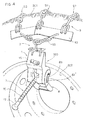
- FIG 3 a large wheel 200, such as a wheel of a truck or the like, is partially shown.
- the wheel 200 has a very wide tyre 201 mounted on a rim 202.
- the hook 32 of the first coupling means 3 of the coupling and tensioning device 100 is permanently coupled to a link of the front portion of chain 93.
- the outer flange 90 of the chain 9 is disposed on the outside wall of the tyre 201.
- the three portions of chain 92 are disposed on the tread of the tyre 201 and the inner flange 91 is disposed on the inside wall of the tyre.
- the coupling and tensioning device 100 abuts against the outer part of the rim 202 and the outside wall of the tyre 201.
- the terminal portion of chain 95 is passed through one of the holes in the rim 202 to be brought into the outward facing part of the wheel, so that the hook 71 of the second coupling means 7 hooks into a link of the terminal portion of chain 95.
- the user pulls on the cable 70 by means of the knob 72 so as to perform a first mild tensioning of the terminal portion 95 and thus of the snow chains 9.
- the cable 70, passing through the anti-return block 5, can slide only in the tensioning direction and not in the slackening direction, thus avoiding any unwanted slackening of the chains 9.
- the user gripping the handle 81, operates the lever operating means 8 by pulling the handle towards himself, that is to say by moving it away from the rim of the wheel.
- the discoid part 82 of the levers 80 turns around the first pivot 84 and the cam-shaped slot 83 pushes the second pivot 85, causing an outward translation of the anti-return block 5 which also pulls with it the cable 70 and thus allows a further tensioning of the terminal portion of chain 95 and of the snow chains 9.
- the lever 80 is prevented from coming back by the hooked end 83' of the cam-shaped slot 83, in which the pivot 85 comes to rest.
- the user simply operates the operating lever 8 pushing it towards the rim of the wheel, thus causing an inward translation of the anti-return block 5 and a first slackening of the chains 9. Afterwards, the user pushes with a finger on the button of the pawl 53 of the anti-return block 5, allowing sliding of the cable 70 in the direction of slackening of the chains.
- the operating movements of the lever means 8 can be inverted with respect to what is described above, that is to say the handle 81 can be pushed towards the wheel rim for tightening the chains and the handle 81 can be pulled away from the wheel rim for slackening the chains.
- a plurality of strap-on chains 9 with the respective coupling and tensioning devices 100 can be mounted on a wheel 200.
- Three strap-on chains 9 disposed at an equal distance from each other are preferably mounted on a truck wheel.
- the hook 32 of the first coupling means 3 is hinged rotatably in the plate 30 to allow reversibility of the snow chains 9. That is to say, when the surface of the chains 9 that abuts on the ice or on the asphalt deteriorates, the chains can be turned of 180° so that the deteriorated part abuts on the tyre tread, without the need to detach the hook 32 of the coupling and tensioning device from the snow chains.
- the body 1 of the coupling and tensioning device can be made of plastic to avoid deterioration of the wheel rim.
- the body 1 can be made in a single piece by injection moulding or it can be made in two shell halves that can be assembled together.
Landscapes
- Engineering & Computer Science (AREA)
- Mechanical Engineering (AREA)
- Tires In General (AREA)
Abstract
Description
- The present invention relates to a coupling and tensioning device for snow chains or anti-skid devices designed to be mounted on the tyres of vehicles. Said coupling and tensioning device is particularly suitable to be applied to lengths of emergency snow chains, commonly called strap-on chains and generally used in wheels of large vehicles, such as trucks and the like.
- When a vehicle is on a road surface covered by snow, sleet or ice, its tyres do not have a good grip and dangerous skidding and sliding can occur. To avoid said drawbacks, it is customary to use anti-skid devices, commonly called snow chains.
- Snow chains, normally mounted on the driving wheels of the vehicle, by biting into the snow and/or ice deposited on the road surface, increase the traction on the tread, permitting good holding by the tyres of the vehicle.
- In cases of emergency and especially for large tyres, such as those of trucks, emergency snow chains called strap-on chains are widely marketed. A strap-on chain generally comprises three lengths of chain disposed parallel, the ends of which are connected to two flanges, so that the lengths of chain abut on the tread of the tyre and the flanges abut respectively on the inside and outside walls of the tyre.
- A terminal length of chain is connected to the flange disposed on the inside wall of the tyre and is passed through one of the holes in the wheel rim to hook on to a coupling and tensioning device connected to the flange disposed on the outside wall of the tyre.
- The coupling and tensioning devices according to the prior art generally comprise a tie rod, which is hooked at one end and threaded at the other. The threaded end of the tie rod is connected by means of a nut to a plate in turn connected to the outer flange. In this manner the user hooks a link of the terminal length of chain to the hook of the tie rod and then, by means of a special tool such as a spanner, tightens the nut to tension the strap-on chain.
- It is evident that the both the mounting and removal operations for strap-on chains are complex, laborious, require the possession of special tools and do not ensure perfect tensioning of the strap-on chain.
- Furthermore, it should be noted that for reasons of safety the connecting plate between the tie rod and the outer flange is made of metal and since it abuts against the edge of the wheel rim, can cause damage or deterioration thereof.
- The object of the present invention is to overcome the drawbacks of the prior art, providing a coupling and tensioning device for snow chains that is safe, efficient and such as to allow perfect tensioning of the snow chains, avoiding any accidental slackening.
- Another object of the present invention is to provide a coupling and tensioning device for snow chains that is practical and easy to use for the user and at the same time allows extremely rapid mounting of the snow chains.
- Another object of the present invention is to provide a coupling and tensioning device for snow chains that is able to avoid damage to and deterioration of the wheel rim of the vehicle whereon it is mounted.
- Yet another object of the present invention is to provide a coupling and tensioning device for snow chains that is cheap and simple to make.
- These objects are achieved in accordance with the invention with the characteristics listed in appended
independent claim 1. - Advantageous embodiments of the invention are apparent from the dependent claims.
- The coupling and tensioning device according to the invention is suitable to be applied to chains comprising an outer flange able to be placed on the outside wall of the tyre, an inner flange able to be positioned on the inside wall of the tyre, said flanges being joined by variously composed elements creating the traction on the tread.
- The coupling and tensioning device comprises first coupling means designed to couple with the outer flange and second coupling means designed to couple with a terminal portion connected to the inner flange.
- The peculiar characteristic of the invention is represented by the fact that the coupling and tensioning device comprises:
- a main body, to which the first coupling means are connected,
- a non-return block, slidably mounted in the main body and able to receive second coupling means to allow a first mild tensioning of the snow chains by pulling manually on the second coupling means, and
- manually operated lever means, mounted in the main body to cause translation of the non-return block and allow a second tensioning of the snow chains.
- From this brief description the advantages of the coupling and tensioning device for snow chains according to the invention are evident.
- In fact, mounting and operation of said device are extremely simple and rapid, without any need to use special tools.
- Furthermore, the possibility of performing a double tensioning by pulling on the second tensioning means and by operating the operating lever allows an efficient and secure tensioning of the snow chains.
- Furthermore, the body of the coupling and tensioning device can be formed by means of plastic shells, avoiding damaging the wheel rim.
- Further characteristics of the invention will be made more apparent by the detailed description that follows, referring to a purely exemplary and therefore non-limiting embodiment thereof, illustrated in the appended drawings, in which:
- Figure 1 is a perspective view illustrating a coupling and tensioning device for snow chains according to the invention;
- Figure 2 is a perspective exploded view illustrating some elements of the coupling and tensioning device of Figure 1, and a strap-on type snow chain, shown broken off and on a reduced scale;
- Figure 3 is a perspective view illustrating a first stage of application of the coupling and tensioning device of Figure 1 to a strap-on chain disposed on a vehicle wheel; and
- Figure 4 is a perspective view, illustrating the coupling and tensioning device of Figure 3 in the ready state for final tensioning of the strap-on chain.
-
- The coupling and tensioning device according to the invention, designated as a whole with
reference numeral 100, will be described with the aid of the figures. - With particular reference for now to Figures 1 and 2, the coupling and
tensioning device 100 comprises amain body 1, fist coupling means 3 mounted at one end of thebody 1, ananti-return block 5 slidably mounted in thebody 1, second coupling means 7 mounted inside theanti-return block 5 and lever operating means 8 connected to thebody 1 to move theanti-return block 5. - The
body 1 is a substantially L-shaped box-type body, with a top part and a larger bottom part. With reference to the figures, thebody 1 has two side walls (only one visible in the figures), afront wall 11 destined to face outwards and a rear wall (not visible in the figure) destined to face towards the vehicle wheel. - A
slot 13, open towards the outside at the bottom, is formed in the bottom part of thebody 1. Theslot 13 communicates with a widenedcentral seat 14 rectangular in section. - A transverse, rectilinear through
slot 19 which runs from oneside wall 10 to the other side wall of thebody 1 passing through thecentral seat 14, is provided in the bottom part of thebody 1. - A transverse through
hole 20, which runs from aside wall 10 to the other side wall of thebody 1 passing through thecentral seat 14, is provided aligned to thetransverse slot 19. - A threaded
hole 22 to receive abolt 16 for mounting acoupling plate 15 is provided on thefront surface 11 of the top part of thebody 1. Thecoupling plate 15 is bent substantially in a Z shape, so that it protrudes forward from thefront surface 11. - Two
slots 17 parallel to each other are formed at the top end of thebody 1. Theslots 17 are passed through by a transverse throughhole 18, which pass through thebody 1 from one side wall to the other. - The first coupling means 3 comprise a
rectangular plate 30, to which two "ring rivets" 31 are fixed. Ahook 32, which protrudes in the opposite direction with respect to the ring rivets 31, is hinged in a central position of theplate 30. Hook 32 can rotate around its axis, which is at right angle to the plane of theplate 30. - The two
ring rivets 31 are so disposed to be able to engage in the twoslots 17 of the main body. Then, apin 38, which passes inside the ring, rivets 31 so as to constrain the first coupling means 3 is inserted in the transverse throughhole 18 in the front part of thebody 1. It should be noted that thering rivets 31 can turn around the axis of thepin 38 and that thehook 32 can turn around an axis substantially at right angles to the axis of thepin 38. - The
anti-return block 5 is of the type commonly known in the technical field of snow chains. An example of an anti-return block is described in patent application EP 1.132.221 in the name of the same applicant. - The
anti-return block 5 comprises anouter shell 50 having aparallelepiped portion 51 suitable to be inserted in thecentral seat 14 of thebody 1, so as to be to slide therein. - A
pawl 53 having one end shaped as a button that can be operated with a finger by the user is hinged in 52 in theanti-return block 5. Thepawl 53 is urged by a spring (not shown in the figures) disposed inside theshell 50 so that the other end (not visible in the figures) of thepawl 53 is situated in a throughslot 54 defined in theshell 50 and delimited by asupport 55 having a flared entry profile. In any case, when theanti-return block 5 is inserted into thebody 1, the button-shaped end of thepawl 53 is accessible from the outside to be operated by the user's finger. - A transverse through
hole 56 is provided in theparallelepiped part 51 of theanti-return block 5. - The second coupling means 7 comprise a
cable 70 for anti-return devices of the type commonly known in the technical field of snow chains. An example of a cable for anti-return devices is described in patent application EP 1.132.221 in the name of the same applicant. - The
cable 70 consists of a plurality of rounded stop elements disposed one behind the other and spaced out at a suitable pitch. In this manner thecable 70 can be inserted in theslot 54 of theanti-return block 5 and slide in the anti-return block so that the end of thepawl 53 of the anti-return block abuts against a stop element of thecable 70 stopping sliding of the cable in one direction. In this manner thepawl 53 acts as a jack for theanti-return block 5 and can be released by manual operation. Sliding of thecable 70 in the anti-return block is favoured by the flared profile of theentry support 55. - A
hook 71 is provided at one end of thecable 70, whilst at the other end of the cable 70 amushroom knob 72 is provided such as to provide a handgrip for pulling on thecable 70. - The lever operating means 8 comprise two
levers 80 parallel to each other, connected at their ends by means of atransverse handle 81 suitable to be gripped by the user. - At the other end, each
lever 80 has adiscoid part 82. An arched cam-shapedslot 83 and a pivot hole are provided in thediscoid part 82 of eachlever 80. The cam-shapedslot 83 has two ends: a first end distal to the pivot hole and a second end proximal to the pivot hole. - In this manner the
discoid parts 82 of the twolevers 80 are disposed in abutment against the side surfaces 10 in the bottom part of thebody 1. Then, afirst pivot 84 is inserted in the holes in the discoid parts of thelevers 80 and in thetransverse hole 20 of thebody 1, so as to pivot the lever operating means 8 to thebody 1. - A
second pivot 85 is passed through the cam-shapedslots 83 of thelevers 80 through therectilinear slot 19 of thebody 1 and through the transverse throughhole 56 of theanti-return block 5. In this manner manual operation of the lever means 8 causes a rotation of thelevers 80 around thepivot axis 84. - In Figure 1, the
second pivot 85 is shown abutting on the distal end of the cam-shapedslot 83. When the operatinglever 80 is rotated around thefirst pivot 84, thesecond pivot 85 follows the cam run defined by the cam-shapedslot 83 and moves in the proximal end of the cam-shapedslot 83. As a result thesecond pivot 85 is moved in translation inside therectilinear slot 19 of thebody 1. Consequently theanti-return block 5, which is constrained to thepivot 85, also performs a translation inside theslot 13 of thebody 1. - In accordance with the above, by operating the lever means 8 the
anti-return block 5 can perform a translation inside thebody 1 passing from a retracted resting position to a forward tensioning position. - The stroke of the
anti-return block 5 is determined by the shape of the cam-shapedslot 83, the ends of which 83', 83" form stops for thepivot 85. - The coupling and
tensioning device 100 is suitable to be applied to asnow chain 9 of the strap-on type, like that shown in Figure 2. The strap-onchain 9 comprises a front orouter flange 90 and a rear orinner flange 91 to which three portions ofchains 92 disposed parallel to each other are applied. - A front portion of
chain 93 is connected to theouter flange 90 and a rear terminal portion ofchain 95 is connected to theinner flange 91 by means of an intermediate portion ofchain 94. - Mounting of the
snow chains 9 with the aid of the coupling andtensioning device 100 according to the invention is described hereunder with reference to Figures 3 and 4. - In Figure 3 a
large wheel 200, such as a wheel of a truck or the like, is partially shown. Thewheel 200 has a verywide tyre 201 mounted on arim 202. - The
hook 32 of the first coupling means 3 of the coupling andtensioning device 100 is permanently coupled to a link of the front portion ofchain 93. Theouter flange 90 of thechain 9 is disposed on the outside wall of thetyre 201. The three portions ofchain 92 are disposed on the tread of thetyre 201 and theinner flange 91 is disposed on the inside wall of the tyre. - In this situation, the coupling and
tensioning device 100 abuts against the outer part of therim 202 and the outside wall of thetyre 201. The terminal portion ofchain 95 is passed through one of the holes in therim 202 to be brought into the outward facing part of the wheel, so that thehook 71 of the second coupling means 7 hooks into a link of the terminal portion ofchain 95. - At this point the user pulls on the
cable 70 by means of theknob 72 so as to perform a first mild tensioning of theterminal portion 95 and thus of thesnow chains 9. It should be noted that thecable 70, passing through theanti-return block 5, can slide only in the tensioning direction and not in the slackening direction, thus avoiding any unwanted slackening of thechains 9. - At this point the user, gripping the
handle 81, operates the lever operating means 8 by pulling the handle towards himself, that is to say by moving it away from the rim of the wheel. In this manner thediscoid part 82 of thelevers 80 turns around thefirst pivot 84 and the cam-shapedslot 83 pushes thesecond pivot 85, causing an outward translation of theanti-return block 5 which also pulls with it thecable 70 and thus allows a further tensioning of the terminal portion ofchain 95 and of thesnow chains 9. Thelever 80 is prevented from coming back by the hooked end 83' of the cam-shapedslot 83, in which thepivot 85 comes to rest. - Lastly, the user hooks the
cable 7 into thecoupling plate 15, so that thecable 7 does not protrude outward from thewheel 200 with the risk of causing unwanted damage. - To remove the snow chains, the user simply operates the operating
lever 8 pushing it towards the rim of the wheel, thus causing an inward translation of theanti-return block 5 and a first slackening of thechains 9. Afterwards, the user pushes with a finger on the button of thepawl 53 of theanti-return block 5, allowing sliding of thecable 70 in the direction of slackening of the chains. - At this point the user unhooks the chains from the coupling means 7 of the coupling and
tensioning device 100 and removes both the chains and the coupling andtensioning device 100 from the wheel. - Clearly, by changing the shape of the cam-shaped
slot 83 with respect to that shown in the drawings, the operating movements of the lever means 8 can be inverted with respect to what is described above, that is to say thehandle 81 can be pushed towards the wheel rim for tightening the chains and thehandle 81 can be pulled away from the wheel rim for slackening the chains. - Clearly, a plurality of strap-on
chains 9 with the respective coupling andtensioning devices 100 can be mounted on awheel 200. Three strap-onchains 9 disposed at an equal distance from each other are preferably mounted on a truck wheel. - It should be noted that the
hook 32 of the first coupling means 3 is hinged rotatably in theplate 30 to allow reversibility of thesnow chains 9. That is to say, when the surface of thechains 9 that abuts on the ice or on the asphalt deteriorates, the chains can be turned of 180° so that the deteriorated part abuts on the tyre tread, without the need to detach thehook 32 of the coupling and tensioning device from the snow chains. - Clearly the
body 1 of the coupling and tensioning device can be made of plastic to avoid deterioration of the wheel rim. Thebody 1 can be made in a single piece by injection moulding or it can be made in two shell halves that can be assembled together. - Numerous changes and modifications of detail within the reach of a person skilled in the art can be made to the present embodiment of the invention, without departing from the scope of the invention as set forth in the appended claims.
Claims (10)
- A coupling and tensioning device (100) for snow chains (9) comprising an outer flange (90) suitable to be placed on the outside wall of a tyre (201), an inner flange (91) suitable to be positioned on the inside wall of the tyre (201), said flanges being joined by variously composed elements (92) creating the traction on the tread, said coupling and tensioning device (100) comprising first coupling means (3) designed to couple to said outer flange (90) and second coupling means (7) designed to couple to a chain terminal portion (95) connected to said inner flange (91), characterised in that it comprises:a main body (1) bearing said first coupling means (3),an anti-return block (5) slidably mounted in said main body (1) and able to receive said second coupling means (7) to allow a first mild tensioning of the snow chains (9) by manual pulling of said second coupling means (7), andmanually operated lever means (8) mounted in said main body (1) to cause a translation of said anti-return block (5) and to allow a further tensioning of said snow chains (9).
- A coupling and tensioning device (100) according to claim 1, characterised in that said second coupling means (7) comprise a cable (70), consisting of a plurality of stop elements, able to slide in said anti-return block (5) in the tensioning direction of the snow chains (9), said cable (70) having at one end a hook (71) able to engage in a link of said terminal portion (95) of the snow chains.
- A coupling and tensioning device (100) according to claim 2, characterised in that a knob (72) is provided at the end of said cable (70) opposite to the hook (71) to facilitate manual pulling on the cable by the user.
- A coupling and tensioning device (100) according to claim 2 or 3, characterised in that a coupling plate (15), able to couple said cable (70) to prevent outward protrusion thereof, is mounted on the front surface of said main body (1).
- A coupling and tensioning device (100) according to any one of the preceding claims, characterised in that said manually operated lever means (8) comprise at least one lever (80) pivoted in said main body (1) by means of a first pivot (84) and having a cam-shaped slot (83) wherein a second pivot (85) constrained to said anti-return block (5) engages.
- A coupling and tensioning device (100) according to claim 5, characterised in that said main body (1) comprises a seat (14) wherein said anti-return block (5) is slidably mounted, a transverse hole (20) wherein said first pivot (84) of said lever (80) of the lever operating means (8) engages and a rectilinear transverse slot (19) wherein said second pivot (85) of said lever (80) of the lever operating means (8) engages.
- A coupling and tensioning device (100) according to claim 5 or 6, characterised in that said anti-return block (5) comprises a transverse through hole (56) wherein said second pivot (85) engaged in said cam slot (83) of said lever (80) of the lever operating means (8) engages.
- A coupling and tensioning device (100) according to any one of the preceding claims, characterised in that said lever operating means (8) comprise two levers (80) pivoted in the side walls of said main body (1) and connected at their free ends by a transverse handle (81) which can be gripped by the user.
- A coupling and tensioning device (100) according to any one of the preceding claims, characterised in that said anti-return block (5) has a pawl (53) urged by a spring and provided at one end with an release button protruding forward from said body (1) to be able to be operated by the user for slackening of the snow chains.
- A coupling and tensioning device (100) according to any one of the preceding claims, characterised in that said first coupling means (3) comprise a hook (32) rotatably mounted with respect to said main body (1) so as to allow rotation of said snow chains (9).
Priority Applications (2)
| Application Number | Priority Date | Filing Date | Title |
|---|---|---|---|
| DE2002606949 DE60206949T2 (en) | 2002-12-30 | 2002-12-30 | Connecting and tensioning device for snow chains |
| EP20020425812 EP1435304B1 (en) | 2002-12-30 | 2002-12-30 | Coupling and tensioning device for snow chains |
Applications Claiming Priority (1)
| Application Number | Priority Date | Filing Date | Title |
|---|---|---|---|
| EP20020425812 EP1435304B1 (en) | 2002-12-30 | 2002-12-30 | Coupling and tensioning device for snow chains |
Publications (2)
| Publication Number | Publication Date |
|---|---|
| EP1435304A1 true EP1435304A1 (en) | 2004-07-07 |
| EP1435304B1 EP1435304B1 (en) | 2005-10-26 |
Family
ID=32479865
Family Applications (1)
| Application Number | Title | Priority Date | Filing Date |
|---|---|---|---|
| EP20020425812 Expired - Lifetime EP1435304B1 (en) | 2002-12-30 | 2002-12-30 | Coupling and tensioning device for snow chains |
Country Status (2)
| Country | Link |
|---|---|
| EP (1) | EP1435304B1 (en) |
| DE (1) | DE60206949T2 (en) |
Cited By (1)
| Publication number | Priority date | Publication date | Assignee | Title |
|---|---|---|---|---|
| KR20060050065A (en) * | 2004-07-29 | 2006-05-19 | 툴레 에스피에이 | Non-turn block for snow chain |
Citations (3)
| Publication number | Priority date | Publication date | Assignee | Title |
|---|---|---|---|---|
| US1980362A (en) * | 1932-03-07 | 1934-11-13 | Columbus Mckinnon Chain Corp | Buckle plate |
| EP0323922B1 (en) * | 1988-01-04 | 1993-04-21 | Ets Cablac | Chain element for a pneumatic tyre |
| EP1132221A1 (en) * | 2000-02-22 | 2001-09-12 | König S.p.A. | Cable for anti-return device particulary for anti-skid devices |
-
2002
- 2002-12-30 DE DE2002606949 patent/DE60206949T2/en not_active Expired - Fee Related
- 2002-12-30 EP EP20020425812 patent/EP1435304B1/en not_active Expired - Lifetime
Patent Citations (3)
| Publication number | Priority date | Publication date | Assignee | Title |
|---|---|---|---|---|
| US1980362A (en) * | 1932-03-07 | 1934-11-13 | Columbus Mckinnon Chain Corp | Buckle plate |
| EP0323922B1 (en) * | 1988-01-04 | 1993-04-21 | Ets Cablac | Chain element for a pneumatic tyre |
| EP1132221A1 (en) * | 2000-02-22 | 2001-09-12 | König S.p.A. | Cable for anti-return device particulary for anti-skid devices |
Cited By (1)
| Publication number | Priority date | Publication date | Assignee | Title |
|---|---|---|---|---|
| KR20060050065A (en) * | 2004-07-29 | 2006-05-19 | 툴레 에스피에이 | Non-turn block for snow chain |
Also Published As
| Publication number | Publication date |
|---|---|
| EP1435304B1 (en) | 2005-10-26 |
| DE60206949T2 (en) | 2006-07-27 |
| DE60206949D1 (en) | 2005-12-01 |
Similar Documents
| Publication | Publication Date | Title |
|---|---|---|
| FI87329C (en) | SNOEKEDJA FOER FORDONSHJUL | |
| US6089291A (en) | Self-tensioning device for snow chains | |
| CA2905152C (en) | Tire chain tool | |
| US6681657B2 (en) | System for installing chains on vehicle tires | |
| EP1435304B1 (en) | Coupling and tensioning device for snow chains | |
| US6539995B2 (en) | Releasing device for snow chains | |
| US20060053976A1 (en) | Tire cuff | |
| US4192367A (en) | Anti-skid wheel attachment device | |
| US4306602A (en) | Tire chain tightener | |
| US20040055684A1 (en) | Traction device | |
| US20090314405A1 (en) | Tire traction device | |
| US6263554B1 (en) | System for installing chains on vehicle tires | |
| CA2351102C (en) | System for installing chains on vehicle tires | |
| US2705520A (en) | Non-skid chain | |
| US4282916A (en) | Easily mounted anti-skid tire chain | |
| EP1221386B1 (en) | Locking device for snow chains | |
| US3188893A (en) | Tire chain applying devices | |
| EP1072448B1 (en) | Self-tensioning device for snow chains | |
| US2063439A (en) | Tensioning device for antiskid armor | |
| US3479910A (en) | Device for applying skid chains to tires | |
| US3099928A (en) | Anti-skid chain operating device | |
| EP0993970A1 (en) | Anti-skid device with improved release system | |
| HU210372B (en) | Central clamp of snow bridles fixable onto tyre of vehicles | |
| EP1180439B1 (en) | Fastening device for a cable for snow chains | |
| KR101499560B1 (en) | Snow chain |
Legal Events
| Date | Code | Title | Description |
|---|---|---|---|
| PUAI | Public reference made under article 153(3) epc to a published international application that has entered the european phase |
Free format text: ORIGINAL CODE: 0009012 |
|
| AK | Designated contracting states |
Kind code of ref document: A1 Designated state(s): AT BE BG CH CY CZ DE DK EE ES FI FR GB GR IE IT LI LU MC NL PT SE SI SK TR |
|
| AX | Request for extension of the european patent |
Extension state: AL LT LV MK RO |
|
| 17P | Request for examination filed |
Effective date: 20041222 |
|
| GRAP | Despatch of communication of intention to grant a patent |
Free format text: ORIGINAL CODE: EPIDOSNIGR1 |
|
| AKX | Designation fees paid |
Designated state(s): DE FR IT |
|
| RAP1 | Party data changed (applicant data changed or rights of an application transferred) |
Owner name: THULE S.P.A. |
|
| GRAS | Grant fee paid |
Free format text: ORIGINAL CODE: EPIDOSNIGR3 |
|
| GRAA | (expected) grant |
Free format text: ORIGINAL CODE: 0009210 |
|
| AK | Designated contracting states |
Kind code of ref document: B1 Designated state(s): DE FR IT |
|
| REF | Corresponds to: |
Ref document number: 60206949 Country of ref document: DE Date of ref document: 20051201 Kind code of ref document: P |
|
| ET | Fr: translation filed | ||
| PLBE | No opposition filed within time limit |
Free format text: ORIGINAL CODE: 0009261 |
|
| STAA | Information on the status of an ep patent application or granted ep patent |
Free format text: STATUS: NO OPPOSITION FILED WITHIN TIME LIMIT |
|
| 26N | No opposition filed |
Effective date: 20060727 |
|
| PGFP | Annual fee paid to national office [announced via postgrant information from national office to epo] |
Ref country code: DE Payment date: 20080131 Year of fee payment: 6 |
|
| PGFP | Annual fee paid to national office [announced via postgrant information from national office to epo] |
Ref country code: FR Payment date: 20071227 Year of fee payment: 6 |
|
| REG | Reference to a national code |
Ref country code: FR Ref legal event code: ST Effective date: 20090831 |
|
| PG25 | Lapsed in a contracting state [announced via postgrant information from national office to epo] |
Ref country code: DE Free format text: LAPSE BECAUSE OF NON-PAYMENT OF DUE FEES Effective date: 20090701 |
|
| PG25 | Lapsed in a contracting state [announced via postgrant information from national office to epo] |
Ref country code: FR Free format text: LAPSE BECAUSE OF NON-PAYMENT OF DUE FEES Effective date: 20081231 |
|
| PGFP | Annual fee paid to national office [announced via postgrant information from national office to epo] |
Ref country code: IT Payment date: 20101227 Year of fee payment: 9 |
|
| PG25 | Lapsed in a contracting state [announced via postgrant information from national office to epo] |
Ref country code: IT Free format text: LAPSE BECAUSE OF NON-PAYMENT OF DUE FEES Effective date: 20111230 |