EP1435206B1 - Socks and method of manufacturing the socks - Google Patents
Socks and method of manufacturing the socks Download PDFInfo
- Publication number
- EP1435206B1 EP1435206B1 EP02767919.0A EP02767919A EP1435206B1 EP 1435206 B1 EP1435206 B1 EP 1435206B1 EP 02767919 A EP02767919 A EP 02767919A EP 1435206 B1 EP1435206 B1 EP 1435206B1
- Authority
- EP
- European Patent Office
- Prior art keywords
- section
- sock
- heel section
- knitted
- toe
- Prior art date
- Legal status (The legal status is an assumption and is not a legal conclusion. Google has not performed a legal analysis and makes no representation as to the accuracy of the status listed.)
- Expired - Lifetime
Links
- 238000004519 manufacturing process Methods 0.000 title claims description 6
- 238000009940 knitting Methods 0.000 claims description 45
- 210000000474 heel Anatomy 0.000 description 120
- 210000003371 toe Anatomy 0.000 description 93
- 210000001255 hallux Anatomy 0.000 description 59
- 210000002683 foot Anatomy 0.000 description 55
- 210000003423 ankle Anatomy 0.000 description 49
- 210000000454 fifth toe Anatomy 0.000 description 21
- 239000004744 fabric Substances 0.000 description 19
- 238000000034 method Methods 0.000 description 3
- 238000005516 engineering process Methods 0.000 description 2
- 210000002082 fibula Anatomy 0.000 description 2
- 238000003825 pressing Methods 0.000 description 2
- 210000004233 talus Anatomy 0.000 description 2
- 208000007366 Genu Valgum Diseases 0.000 description 1
- 208000010300 Genu Varum Diseases 0.000 description 1
- 206010062061 Knee deformity Diseases 0.000 description 1
- 210000000459 calcaneus Anatomy 0.000 description 1
- 230000000694 effects Effects 0.000 description 1
- 210000002414 leg Anatomy 0.000 description 1
Images





Classifications
-
- D—TEXTILES; PAPER
- D04—BRAIDING; LACE-MAKING; KNITTING; TRIMMINGS; NON-WOVEN FABRICS
- D04B—KNITTING
- D04B1/00—Weft knitting processes for the production of fabrics or articles not dependent on the use of particular machines; Fabrics or articles defined by such processes
- D04B1/22—Weft knitting processes for the production of fabrics or articles not dependent on the use of particular machines; Fabrics or articles defined by such processes specially adapted for knitting goods of particular configuration
- D04B1/24—Weft knitting processes for the production of fabrics or articles not dependent on the use of particular machines; Fabrics or articles defined by such processes specially adapted for knitting goods of particular configuration wearing apparel
- D04B1/26—Weft knitting processes for the production of fabrics or articles not dependent on the use of particular machines; Fabrics or articles defined by such processes specially adapted for knitting goods of particular configuration wearing apparel stockings
-
- A—HUMAN NECESSITIES
- A41—WEARING APPAREL
- A41B—SHIRTS; UNDERWEAR; BABY LINEN; HANDKERCHIEFS
- A41B11/00—Hosiery; Panti-hose
-
- D—TEXTILES; PAPER
- D04—BRAIDING; LACE-MAKING; KNITTING; TRIMMINGS; NON-WOVEN FABRICS
- D04B—KNITTING
- D04B1/00—Weft knitting processes for the production of fabrics or articles not dependent on the use of particular machines; Fabrics or articles defined by such processes
- D04B1/10—Patterned fabrics or articles
- D04B1/102—Patterned fabrics or articles with stitch pattern
- D04B1/108—Gussets, e.g. pouches or heel or toe portions
-
- D—TEXTILES; PAPER
- D04—BRAIDING; LACE-MAKING; KNITTING; TRIMMINGS; NON-WOVEN FABRICS
- D04B—KNITTING
- D04B15/00—Details of, or auxiliary devices incorporated in, weft knitting machines, restricted to machines of this kind
- D04B15/14—Needle cylinders
Definitions
- the present invention relates to hosiery and a method of manufacturing hosiery, more precisely relates to hosiery knitted by a hosiery knitting machine and method of manufacturing the hosiery.
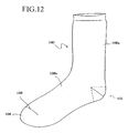
- a conventional sock 100 shown in Fig. 12 is manufactured by cylindrically knitting a cylindrical knitted part 106a from an inlet part toward a heel section 102, and knitting the heel section 102. Further, a cylindrical knitted part 106b is cylindrically knitted from the heel section 102 toward a tip toe section 104, then an opening formed in an instep part of the cylindrical knitted part 106b is seamed to finish the sock. In Fig. 12 , the seamed opening is shown as a seam line 108.
- the sock 100 shown in Fig. 12 is manufactured by, for example, a circular knitting machine having a needle holder, in which a plurality of knitting needles are provided on an outer circumferential face of a needle holder which is capable of rotating in a prescribed direction and turning in a normal direction and a reverse direction so as to knit the sock.
- the knitting needle has a hook section 52, which is formed at a front end, and a tongue section 54, whose one end is pivotably attached to a neck part of the hook section 52 by a shaft 56 so as to open and close the hook.
- the needle holder has a cylindrical member 62 and a plurality of longitudinal grooves 64, 64,...
- the knitting needles 50 shown in Fig. 13A are respectively inserted in the grooves 64 and capable of moving upward and downward.
- the knitting needles 50 are moved upward in order at a prescribed position so as to knit the sock.
- the sock 100 shown in Fig. 12 which has been manufactured by the knitting machine including the needles shown in Fig. 13A and the needle holder shown in Fig. 13B , is symmetrically formed, so that the sock can be put on a right foot and a left foot.
- the sock 100 shown in Fig. 12 has the symmetrical tip toe section 104; if it is put on an asymmetrical human foot, whose tip top is positioned nearer to a big toe side and which has a big toe thicker and longer than other toes, cloth of the sock is pulled by the big toe so that the big toe and a little toe of the person are pressed.
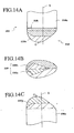
- a tip toe section 204 of a sock 200 shown in Figs. 14A-14C has an asymmetrical shape, in which a tip position G is shifted on a big toe side with respect to a center line X and in which a gusset part 220 for making bulge of the tip toe section 204 on the big toe side larger than that of the little toe side is knitted nearer to the big toe side of the tip toe section 204.
- Fig. 14A shows the tip toe section 204 seen from an instep side of the sock 200, wherein a seam line 208 is formed on the instep section of the sock 200.
- Fig. 14B shows the tip toe section 204 seen from a front end side of the sock 200
- Fig. 14C shows the tip toe section 204 seen from a sole part side of the sock 200.
- the gusset part 220 of the sock 200 shown in Figs. 14A-14C is constituted by a gusset part 220a of the sole part and a gusset part 220b of the instep section.
- the shape of the sock 200 having the tip toe section 204 is similar to that of the foot, whose big toe is thicker than other toes, so that foot comfort of the sock is better than that of the sock 100 shown in Fig. 12 .
- a length of the big toe side of the tip toe section 204 which is equal to a distance from a border between the tip toe section 204 and the sole part 206a or the instep section 206b (the widest portion of the tip toe section 204) to the tip position G, i.e., a distance between the seam line 208 and the tip position G, is too short for a foot whose big toe is longer than a little toe.
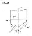
- the shape becomes the tip toe section 204' shown in Fig. 15 , wherein a length of the little toe side of the tip toe section 204' (a distance between an outermost edge of an inlet section, from which a foot is inserted, and the seam line 208) is also elongated as well as the big toe side. Therefore, when the sock having the tip toe section 204' is put on, cloth is slacken off on the little toe side, so that foot comfort is not good.
- the shape becomes the tip toe section 204" shown in Fig. 15 , wherein the tip position G of the tip toe section 204" is close to the center line X so that the shape of the tip toe section 204" becomes a symmetrical shape. Therefore, by putting on the sock having the tip toe section 204", the big toe and the little toe are pressed, so that foot comfort is not good.
- An object of the present invention is to provide hosiery, which has good foot comfort for walking and which is capable of preventing cloth of an inner ankle part and an outer ankle part of a heel section from damaging, and a method of manufacturing the hosiery.
- the inventors of the present invention has studied to achieve the object and found that: by forming a gusset part nearer to one side of a heel section, the hosiery has good foot comfort for walking and is capable of preventing cloth of an inner ankle part and an outer ankle part of a heel section from damaging.
- an asymmetrical heel section includes a gusset part positioned nearer to one side of the heel section, and an edge of said gusset part locates at the one side of the heel section when the person wear said hosiery.
- a method for achieving the object is a method of manufacturing hosiery knitted by a hosiery knitting machine, wherein a heel section of the hosiery is knitted with shifting a knitting direction of the hosiery knitting machine toward one side of the heel section so that a gusset part is knitted near to the one side of the heel section.
- an asymmetrical heel section may include a third gusset part positioned nearer to one side of the heel section, and an edge of the third fourchett part may locate at the one side of the heel section when the person wear the hosiery; with this structure, the hosiery can have good foot comfort for walking and is capable of preventing cloth of the inner ankle part and the outer ankle part of the heel section from damaging.
- the gusset part is knitted one-sided or the edge of the fourchett part locates at the one side of the heel section, so that the heel section is asymmetrically formed.
- Figs. 1A-1C are explanation views of a sock relating to the present invention
- Fig. 2 is an explanation view explaining functions and effects of the sock
- Fig. 3 is a partial side view of the sock shown in Fig. 1
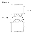
- Fig. 4A is a side view of a heel section seen from a direction of an arrow D
- Fig. 4B is a side view of the heel section seen from a direction of an arrow E
- Fig. 5 is an explanation view showing a skeletal structure of a human leg
- Fig. 6A is a side view of a heel section of a modified sock for a left foot seen from one side
- FIG. 6B is a perspective view of the heel section of the modified sock for the left foot seen from the other side;
- Fig. 7A is a partial side view of the heel section of the modified sock for the left foot seen from the direction of an arrow B shown in Fig. 6A ;
- Fig. 7B is a partial bottom view of the heel section of the modified sock for the left foot seen from the direction of an arrow C shown in Fig. 6A ;
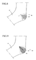
- Fig. 8 is a partial perspective view of another example of the heel section of the modified sock for the left foot;
- Fig. 9 is a partial perspective view of another example of the heel section of the modified sock for the left foot;
- Fig. 7A is a partial side view of the heel section of the modified sock for the left foot seen from the direction of an arrow B shown in Fig. 6A
- Fig. 7B is a partial bottom view of the heel section of the modified sock for the left foot seen from the direction of
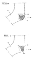
- FIG. 10 is a partial perspective view of another example of the heel section of the modified sock for the left foot
- Fig. 11 is a partial perspective view of another example of the heel section of the modified sock for the left foot
- Fig. 12 is a perspective view of the conventional sock
- Figs. 13A and 13B are explanation views of the circular sock knitting machine
- Figs. 14A-14C are explanation view of another conventional sock modified the sock shown in Fig. 12
- Fig. 15 is an explanation view explaining disadvantages of the tip toe section of the sock shown in Fig. 14 .
- FIG. 1A shows the tip toe section 14 of a sock 10 for a left foot, in which a cylindrical knitted part 12 is seen from an instep part 12b side, and a seam line 20 is formed in the instep part 12b.
- Fig. 1B shows the tip toe section 14 of the sock 10 seen from a tip toe side
- Fig. 1C shows the tip toe section 14 of the sock 10, in which the cylindrical knitted part 12 is seen from a sole part 12a side.
- a left side of the tip toe section 14 is a big toe side 16 covering a big toe of a human foot; a right side of the tip toe section 14 is a little toe side 18 covering a little toe of the human foot.
- the tip toe section 14 of the sock 10 has an asymmetrical shape, in which a tip position G is shifted nearer to the big toe side 16 with respect to a center line Y.
- the shape is similar to the shape of the human foot.
- the tip toe section 14 of the sock 10 has a first gusset part 22, which is knitted nearer to the big toe side 16 of the tip toe section 14, and a second gusset part 24 is knitted nearer to the big toe side 16 following the first gusset part 22.
- bulge of the tip toe section 14 on the big toe side 16 is made larger than that of the little toe side 18 by the first gusset part 22 as shown in Fig. 1B ; the big toe side 16 of the tip toe section 14 is extended without substantially extending the little toe side 18 by the second gusset part 24 as shown in Figs. 1A and 1B .
- the sock 10 shown in Figs. 1A-1C has the asymmetrical shape, in which the tip position G of the tip toe section 14 is located nearer to the big toe side 16 and which is similar to the human foot having the big toe thicker and longer than other toes, so that foot comfort of the sock can be better than that of the sock 200 shown in Fig. 14 .
- the first gusset part 22 is integrally constituted by a sole side part 22a of the first gusset part and an instep side part 22b of the first gusset part;
- the second gusset part 24 is integrally constituted by a sole side part 24a of the second gusset part and an instep side part 24b of the second gusset part.
- the tip position is included in the second gusset part 24, and a side face of the big toe side 16 of the tip toe section 14 is constituted by the first gusset part 22 and the second gusset part 24.
- the big toe side 16 of the tip toe section 14 can be further thicker and longer than the little toe side 18, so that the shape of the tip toe section can be further similar to that of the human foot.
- edges of the first gusset part 22 and the second gusset part 24 make V-shaped lines, whose distance is gradually made longer toward the front end of the tip toe section 14 and which form the bulge of the big toe side 16.
- edges of the first gusset part 22 and the second gusset part 24 forming the V-shaped lines are arranged, in order, toward the front end of the tip toe section 14, and the length of the big toe side 16 is longer than that of the little toe side 18.
- the sock 10 shown in Figs. 1A-1C can be knitted by a known circular knitting machine shown in Figs. 13A and 13B .
- a knitting direction of the needle holder 60 of the circular knitting machine is shifted toward the big toe side of the tip toe section 14, so that the first gusset part 22, which makes the bulge of the tip toe section 14 on the big toe side 16 larger than that of the little toe side, and the second gusset part 24, which is knitted nearer to the big toe side 16 following the first gusset part 22 so as to extend the big toe side 16 without substantially extending the little toe side 18 of the tip toe section 14, are knitted near to the big toe side.
- the needle holder 60 of the circular knitting machine is rotated in a prescribed direction until the cylindrical knitted part 12 having a prescribed length is knitted, then the needle holder 60 is alternately turned in one direction and the reverse direction with changing number of the actually knitting needles 50 until the tip toe section 14 of the sock 10 is knitted.
- the change of the number of the actually knitting needles 50 is performed when the turning direction of the needle holder 60 is changed.
- the tip toe section 14 When the tip toe section 14 is knitted, firstly the section is knitted until reaching a position H-I shown in Fig. 1C , which shows a sole side part 12b of the cylindrical knitted part 12 of the sock 10, then the section is further knitted with gradually reducing the number of the actually knitting needles 50 (the number of the needles) until reaching a position J-K. Note that, number of reducing the needles while the needle holder 60 is turned in one direction and number of reducing the needles while the needle holder is turned in the reverse direction are substantially equal.
- the needle holder 60 After reaching the position J-K, the needle holder 60 is turned toward the position J, and the tip toe section is knitted with gradually increasing the number of the needles until reaching the position H; and the needle holder 60 is turned toward the position K, and the tip toe section is knitted with gradually reducing the number of the needles until reaching a position L.
- the tip toe section is knitted with gradually reducing the number of the needles until reaching a position M-N. Note that, number of reducing the needles while the needle holder 60 is turned in one direction and number of reducing the needles while the needle holder is turned in the reverse direction are substantially equal.
- the knitting direction can be shifted toward the big toe side 16 of the sock 10. Therefore, the sole side part 22a of the first gusset part can be knitted in the sole part 10a of the tip toe section 12 and located nearer to the big toe side 16.
- the needle holder 60 After reaching the position M-N, the needle holder 60 is turned toward the position M, and the tip toe section is knitted with gradually increasing the number of the needles until reaching a position O; and the needle holder 60 is turned toward the position N, and the tip toe section is knitted with gradually reducing the number of the needles until reaching a position P. Therefore, the sole side part 24a of the second gusset part, which follows the sole side part 22a of the first gusset part, can be knitted and located nearer to the big toe side 16.
- the position O is located between the positions M and H.
- the needle holder 60 After reaching the position O-P, the needle holder 60 is further turned toward the position O, and the tip toe section is knitted with gradually reducing the number of the needles until reaching a position Q; and the needle holder 60 is turned toward the position P, and the tip toe section is knitted with gradually increasing the number of the needles until reaching the position N.
- an instep side part 24b of the second gusset part can be formed and integrated with a sole side part 24b so as to form the second gusset part 24.
- the tip toe section is further knitted with gradually increasing the number of the needles until reaching the position H-L. Note that, number of increasing the needles while the needle holder 60 is turned in one direction and number of increasing the needles while the needle holder is turned in the reverse direction are substantially equal.
- a track of an end of the needle holder 60 turning toward the position Q is extended to the position H via the position O.
- the needle holder 60 After reaching the position H-L, the needle holder 60 is turned toward the position H, and the tip toe section is knitted with gradually reducing the number of the needles until reaching a position R; and the needle holder 60 is turned toward the position L, and the tip toe section is knitted with gradually increasing the number of the needles until reaching the position K.
- an instep side part 22b of the first gusset part which follows the instep side part 24b of the second gusset part, can be formed and integrated with the sole side part 22a of the first gusset part so as to form the first gusset part 22.
- the needle holder 60 After reaching the position R-K, the needle holder 60 is turned, and the tip toe section is knitted with gradually increasing the number of the needles until reaching the position H-I. Note that, number of increasing the needles while the needle holder 60 is turned in one direction and number of increasing the needles while the needle holder is turned in the reverse direction are substantially equal.
- the position H-I is an open end of the knitted part in the instep part 12b of the sock 10, and the open end is seamed so that the seam line 20 is formed therein.
- Loops of edges of the knitted parts, which constitute the tip toe section 14, are mutually tangled, so that the edges are mutually connected and constitute connected lines H-J, I-K, K-L-N, H-O-M, N-P, Q-O-H, and R-H.
- the connected lines correspond to ends of turning the needle holder 60.
- the connected line Q-O-M corresponds to edges of the second gusset part 24, which constitutes a part of a front face and a side face of the big toe side 16, and the line is formed into a V-shape, whose is gradually made wider toward the front end of the big toe side 16, when the line is seen from the side of the big toe side 16 of the tip toe section 14 [or seen from a direction of an arrow A shown in Fig. 1B ].
- the connected line R-H-J corresponds to edges of the first gusset part 22, which constitutes a part of a side face of the big toe side 16, and the line is formed into a V-shape, which is gradually made wider toward the front end of the big toe side 16, when the line is seen from the side of the big toe side 16 of the tip toe section 14 [or seen from the direction of the arrow A shown in Fig. 1B ].
- V-shaped lines (the connected lines R-H-J and Q-O-M) of the first gusset part 22 and the second gusset part 24 are arranged, in order, toward the front end of the big toe side 16.
- the expression "substantially equal” means that a difference between the number of increasing or reducing the needles while the needle holder is turned in one direction and the number of increasing or reducing the needles while the needle holder is turned in the reverse direction is 10 % of the number of actually knitting needles or less.
- the big toe side 16 can be extended without substantially extending the little toe side 14.
- the shape of the tip toe section 14 is similar to that of the human foot whose big toe is thicker and longer than the other toes, and the big toe side 16 can be extended without slackening cloth in the little toe side 18 so that foot comfort can be highly improved.
- the heel section 26 is formed as in the conventional sock 100 shown in Fig. 12 .
- the heel section 26 is knitted by the circular knitting machine shown in Fig. 13
- the cylindrical knitted part is knitted until reaching a position X-Y shown in Fig. 4A by rotating the needle holder 60 in a prescribed direction, then the needle holder 60 is alternately turned in one direction and the reverse direction with gradually reducing the number of the needles until reaching a position Z-W shown in Fig. 4A .
- the needle holder 60 After reaching the position Z-W shown in Fig. 4A , the needle holder 60 is alternately turned in one direction and the reverse direction with gradually increasing the number of the needles until reaching the position X-Y shown in Fig. 4B , so that the heel section 26 can be knitted.
- the needle holder 60 After reaching the position X-Y shown in Fig. 4B , the needle holder 60 is rotated in the prescribed direction with maintaining the number of the needles so as to knit the cylindrical knitted part 12.
- the heel section 26 of the sock 10 has a symmetrical shape.
- a human foot looks like symmetrical, but, as shown in Fig. 5 , a heel bone 30 is located nearer to an outer ankle bone (an outer ankle) 32, which is located at an lower end of a fibula, further an arch of foot is located nearer to an inner ankle bone (an inner ankle) 34, so that weight is concentrated to the outer ankle of the heel section 26 while walking.
- an outer ankle bone an outer ankle
- an inner ankle an inner ankle
- the shape of the tip toe section 14 is similar to that of the human foot whose big toe is thicker and longer than other toes, further the shape of the heel section 26 of the sock 10 is similar to that of the human foot, so that foot comfort of the sock 10 can be further improved.
- FIG. 6A is a partial side view of the heel section 36 of a sock 10 for a left foot seen from an outer ankle side
- Fig. 6B is a partial side view of the heel section 36 of the sock 10 for the left foot seen from an inner ankle side.
- a third gusset part 28 is knitted nearer to the outer ankle side of the heel section 36 of the sock 10, and the third gusset part 28 in the heel section 36 is knitted to make an edge of the third gusset part 28 locate on the outer ankle side of the heel section 36 when the sock 10 is put on.
- a partial side view of the heel section 36 seen from a rear side [from the direction of an arrow B shown in Fig. 6A ] is shown in Fig. 7A;
- a partial bottom view of the heel section 36 seen from a sole side [from the direction of an arrow C shown in Fig. 6A ] is shown in Fig. 7B.
- the third gusset part 28 is knitted in the heel section 36 of the sock 10 and located nearer to the outer ankle side.
- the third gusset part 28 which has been knitted nearer to one side, makes a slackened cloth part on the outer ankle side of the heel section 36 of the sock 10.
- the heel section 36 of the sock 10 shown in Figs. 6A, 6B , 7A and 7B may be knitted by the circular knitting machine shown in Figs. 13A and 13B , namely the knitting direction of the circular knitting machine is shifted toward the outer ankle side of the heel section 36 while knitting, so that the third gusset part 28 can be knitted nearer to the outer ankle side of the heel section 36.
- the needle holder 60 of the circular knitting machine is rotated in a prescribed direction until a cylindrical knitted part 11 having a prescribed length is knitted, then the needle holder 60 is alternately turned in one direction and the reverse direction with changing number of the actually knitting needles of the needle holder 60 to knit the heel section 36.
- the change of the number of the actually knitting needles is performed when the turning direction of the needle holder 60 is changed.
- the heel section 36 When the heel section 36 is knitted by alternately turning the needle holder 60 with changing the number of the needles, after the needle holder 60 knitting the cylindrical knitted part 11 reaches a position a-b, the section is knitted until reaching a position c-d with gradually reducing the number of the needles. Note that, number of reducing the needles while the needle holder is turned in one direction and number of reducing the needles while the needle holder is turned in the reverse direction are substantially equal.
- the needle holder 60 After reaching the position c-d, the needle holder 60 is turned toward the position c, and the heel section is knitted with gradually increasing the number of the needles until reaching a position e; and the needle holder 60 is turned toward the position d, and the heel section is knitted with gradually reducing the number of the needles until reaching a position f, so that the heel section 36 can be knitted with shifting the knitting direction toward the outer ankle side of the heel section. Therefore, a rear side part 28a of the third gusset part 28 can be knitted in a rear part of the heel section 36 and located nearer to the outer ankle side.
- the needle holder 60 is turned toward a position f, the heel section is knitted with gradually increasing the number of the needles until reaching the position d; and the needle holder 60 is turned toward the position e, and the heel section is knitted with gradually reducing the number of the needles until reaching a position h [see Fig. 7B], so that the heel section can be knitted with shifting the knitting direction toward the outer ankle side of the heel section 36. Therefore, a front side part 28b of the third gusset part 28 can be knitted in a front part of the heel section 36, and the whole third gusset part 28 is located nearer to the outer ankle side of the heel section 36.
- the needle holder After reaching the position h-d, the needle holder knits with gradually increasing the number of the needles until reaching the position a-b, so that the section 12 can be formed.
- the needle holder knits from the position h-d to the position a-b the number of increasing the needles while the needle holder 60 is turned in one direction and the number of increasing the needles while the needle holder is turned in the reverse direction are substantially equal.
- the third gusset part may be formed by making knitted stitches of the prescribed part of the heel section 36 bigger than other parts of the heel section 36.
- the bigger stitches of the third gusset part can be extended easier than other parts of the heel section 36.
- the third gusset part 28 shown in Figs. 6A, 6B , 7A and 7B is formed by the knitted stitches, which are bigger than stitches of other parts of the heel section 36, area of the third gusset part 28 can be small.
- the third gusset part 28, which is constituted by the knitted stitches bigger than stitches of other parts of the heel section 36, can be extended easier than other parts of the heel section 36.
- the sock 10, whose heel section 36 has the third gusset part 28 may have another gusset part, which is formed in any sections other than the heel section 12 of the sock 10 to which weight is applied during walk, another gusset part may be formed, for example, in a section between the heel section 12 and the tip toe section 14.
- the third gusset part 28 is knitted nearer to the outer ankle side, but if weight is applied to the inner ankle side of the sock during walk and cloth of the inner ankle side is apt to be damaged, the third gusset part 28 may be knitted nearer to the inner ankle side.
- the third gusset part 28 shown in Figs. 6A, 6B , 7A and 7B is mostly formed on the sole side of the sock, but the edges (the connected lines e-c and e-h) of the V-shaped third gusset part 28 may be formed near the ankle so as to shift the whole third gusset part 28 toward the ankle.
- the big third gusset part 28 which is bigger than the third gusset part 28 shown in Fig. 6A , can be formed in one side part of the heel section 36.
- the shape of the third gusset part 28 may be designed according to a shape of a heel of a user who puts on the sock 10.
- a plurality of V-shaped connected lines may be arranged as shown in Fig. 9 so as to arrange a plurality of third gusset parts 28 and 28, and a plurality of V-shaped connected lines may be serially formed as shown in Fig. 10 so as to form the third gusset part 28 in another third gusset part 28.
- a V-shaped connecting line is extended from one of front ends of another V-shaped connecting line as shown in Fig. 11 so as to form a plurality of third gusset parts 28 and 28 like meshes.
- the shape of the heel section 36 can be corresponded to a shape of a heel of a user who puts on the sock 10, and bulge of one side of the heel section 36 can be larger than the other side of the heel section 36.
- the socks are manufactured by the circular knitting machine, but they may be manufactured by a horizontal knitting machine.
- the seam line 20 is formed in the instep part of the sock 10, but the seam line 20 may be formed in the sole part according to designs, further the sock 10 may be knitted without forming the seam line 20.
- the sock 10 for the right foot or the left foot is determined by the tip toe section 14, or the tip toe section 14 and the heel section 36, so a mark for identifying for a right foot or a left foot may be attached to the sock 10.
- Figs. 6A-11 relate to the sock 10 having the tip toe section 14 shown in Figs. 1A-1C , further the heel section 36 shown in Figs. 6A-11 may be applied to a sock 100 shown in Fig. 12 , which has a symmetrical tip toe section 104.
- the third gusset part 28 is formed in one side part of the heel section 36, and the heel section 36 has an asymmetrical shape; the third gusset part 28 is knitted nearer to one side of the heel section 36, so that an edge of the third gusset part 28 locates on the one side of the heel section 36 when the sock 100 is put on.
- the foot comfort of the sock 100 having the heel section 36 shown in Figs. 6A-11 is better than that of the conventional sock 100 shown in Fig. 12 , which has the symmetrical tip toe section 104 and the symmetrical heel section 102.
- heel section 36 shown in Figs. 6A-11 may be applied to a sock 200 having a tip toe section 204 shown in Figs. 14A-14C .
- a tip toe section 204 has an asymmetrical shape, in which a tip position G is located on the big toe side with respect to a center line X, a gusset part 220, which makes bulge of the tip toe section 204 on the big toe side larger than that of the little toe side, is knitted nearer to the big toe side of the tip toe section 204.
- the third gusset part 28 is formed in one side part of the heel section 36, and the heel section 36 has an asymmetrical shape; the third gusset part 28 is knitted nearer to one side of the heel section 36, so that an edge of the third gusset part 28 locates on the one side of the heel section 36 when the sock 200 is put on.
- the shape of the tip toe section 204 is similar to that of a human foot whose big toe is thicker than other toes, and, degree of tensing the cloth on the outer ankle side or the inner ankle side of the heel section 36 can be relieved when a person wearing the sock 200 walks. Therefore, foot comfort of the sock 200, which has the heel section 36 shown in Figs. 6A-11 , is better than that of the sock 200 shown in Figs. 14A-14C , which has the symmetrical heel section 26, and damage of the cloth of the heel section 36 of the sock 200 can be prevented.
- the hosiery is the sock whose length is designed to cover an ankle of a human foot, but the present invention can be applied to other hosiery, e.g., long socks, tights, stockings.
- the shape of the tip toe section is similar to that of a human foot, whose big toe is thicker and longer than other toes. Therefore, a force pressing the big toe toward other toes can be reduced as much as possible, so that pressure to the big toe and the little toe can be reduced.
- the cloth of the little toe side of the tip toe section is not slackened, so that foot comfort of the hosiery can be improved.
- the hosiery is proper for sports, in which a force is applied to the big toe, and effective for preventing deformation of the big toe and the little toe.
Landscapes
- Engineering & Computer Science (AREA)
- Textile Engineering (AREA)
- Socks And Pantyhose (AREA)
- Knitting Of Fabric (AREA)
Description
- The present invention relates to hosiery and a method of manufacturing hosiery, more precisely relates to hosiery knitted by a hosiery knitting machine and method of manufacturing the hosiery.
- A
conventional sock 100 shown inFig. 12 is manufactured by cylindrically knitting a cylindrical knittedpart 106a from an inlet part toward aheel section 102, and knitting theheel section 102. Further, a cylindrical knittedpart 106b is cylindrically knitted from theheel section 102 toward atip toe section 104, then an opening formed in an instep part of the cylindrical knittedpart 106b is seamed to finish the sock. InFig. 12 , the seamed opening is shown as aseam line 108. - The
sock 100 shown inFig. 12 is manufactured by, for example, a circular knitting machine having a needle holder, in which a plurality of knitting needles are provided on an outer circumferential face of a needle holder which is capable of rotating in a prescribed direction and turning in a normal direction and a reverse direction so as to knit the sock. As shown inFig. 13A , the knitting needle has ahook section 52, which is formed at a front end, and atongue section 54, whose one end is pivotably attached to a neck part of thehook section 52 by ashaft 56 so as to open and close the hook. As shown inFig. 13B , the needle holder has acylindrical member 62 and a plurality oflongitudinal grooves knitting needles 50 shown inFig. 13A are respectively inserted in thegrooves 64 and capable of moving upward and downward. By rotating theneedle holder 60 in the prescribed direction, the knittingneedles 50 are moved upward in order at a prescribed position so as to knit the sock. - The
sock 100 shown inFig. 12 , which has been manufactured by the knitting machine including the needles shown inFig. 13A and the needle holder shown inFig. 13B , is symmetrically formed, so that the sock can be put on a right foot and a left foot. - However, the
sock 100 shown inFig. 12 has the symmetricaltip toe section 104; if it is put on an asymmetrical human foot, whose tip top is positioned nearer to a big toe side and which has a big toe thicker and longer than other toes, cloth of the sock is pulled by the big toe so that the big toe and a little toe of the person are pressed. - To solve the problem of pressing the toes caused by the
sock 100 shown inFig. 12 , one of the inventors invented hosiery shown inFigs. 14A-14C , which was disclosed asU.S. Pat. No. 6,000,247 . - A
tip toe section 204 of asock 200 shown inFigs. 14A-14C has an asymmetrical shape, in which a tip position G is shifted on a big toe side with respect to a center line X and in which agusset part 220 for making bulge of thetip toe section 204 on the big toe side larger than that of the little toe side is knitted nearer to the big toe side of thetip toe section 204. -
Fig. 14A shows thetip toe section 204 seen from an instep side of thesock 200, wherein aseam line 208 is formed on the instep section of thesock 200.Fig. 14B shows thetip toe section 204 seen from a front end side of thesock 200, andFig. 14C shows thetip toe section 204 seen from a sole part side of thesock 200. - Note that, the
gusset part 220 of thesock 200 shown inFigs. 14A-14C is constituted by agusset part 220a of the sole part and agusset part 220b of the instep section. - The shape of the
sock 200 having thetip toe section 204 is similar to that of the foot, whose big toe is thicker than other toes, so that foot comfort of the sock is better than that of thesock 100 shown inFig. 12 . - However, in the
tip toe section 204 shown inFigs. 14A-14C , a length of the big toe side of thetip toe section 204, which is equal to a distance from a border between thetip toe section 204 and thesole part 206a or theinstep section 206b (the widest portion of the tip toe section 204) to the tip position G, i.e., a distance between theseam line 208 and the tip position G, is too short for a foot whose big toe is longer than a little toe. - To improve foot comfort of the
sock 200 for the foot whose big toe is thicker and longer than other toes, it is necessary to locate the tip position G of thetip toe section 204 on the big toe side and to extend the distance between theseam line 208 and the tip position G so as to correspond to the big toe side of the foot. - However, if the tip position G is located on the big toe side and the distance between the
seam line 208 and the tip position G is extended with maintaining the shape of thetip toe section 204 shown inFigs. 14A-14C (with maintaining similarity), the shape becomes the tip toe section 204' shown inFig. 15 , wherein a length of the little toe side of the tip toe section 204' (a distance between an outermost edge of an inlet section, from which a foot is inserted, and the seam line 208) is also elongated as well as the big toe side. Therefore, when the sock having the tip toe section 204' is put on, cloth is slacken off on the little toe side, so that foot comfort is not good. - On the other hand, if the distance between the edge of the big toe side of the
tip toe section 204 and theseam line 208 is elongated with limiting elongation of the distance between an edge on the little toe side and theseam line 208, the shape becomes thetip toe section 204" shown inFig. 15 , wherein the tip position G of thetip toe section 204" is close to the center line X so that the shape of thetip toe section 204" becomes a symmetrical shape. Therefore, by putting on the sock having thetip toe section 204", the big toe and the little toe are pressed, so that foot comfort is not good. - When the sock having the tip toe section shown in
Figs. 14A-14C is put on, an inner ankle part and an outer ankle part of the heel section are pulled, so that foot comfort of the sock is made worse and cloth of the ankle parts are apt to be damaged. - An object of the present invention is to provide hosiery, which has good foot comfort for walking and which is capable of preventing cloth of an inner ankle part and an outer ankle part of a heel section from damaging, and a method of manufacturing the hosiery.
- The inventors of the present invention has studied to achieve the object and found that: by forming a gusset part nearer to one side of a heel section, the hosiery has good foot comfort for walking and is capable of preventing cloth of an inner ankle part and an outer ankle part of a heel section from damaging.
- The object is achieved by hosiery knitted by a hosiery knitting machine, wherein an asymmetrical heel section includes a gusset part positioned nearer to one side of the heel section, and an edge of said gusset part locates at the one side of the heel section when the person wear said hosiery.
- A method for achieving the object is a method of manufacturing hosiery knitted by a hosiery knitting machine, wherein a heel section of the hosiery is knitted with shifting a knitting direction of the hosiery knitting machine toward one side of the heel section so that a gusset part is knitted near to the one side of the heel section.
- In the hosiery, an asymmetrical heel section may include a third gusset part positioned nearer to one side of the heel section, and an edge of the third fourchett part may locate at the one side of the heel section when the person wear the hosiery; with this structure, the hosiery can have good foot comfort for walking and is capable of preventing cloth of the inner ankle part and the outer ankle part of the heel section from damaging.
- In the hosiery achieving the object, the gusset part is knitted one-sided or the edge of the fourchett part locates at the one side of the heel section, so that the heel section is asymmetrically formed. With this structure, extension of the cloth of the inner or outer ankle part of the heel section, which occurs when a person puts on the hosiery achieving the object, can be eased, foot comfort can be improved and damaging the cloth of the heel section can be prevented.
-
Figs. 1A-1C are explanation views of a sock relating to the present invention;Fig. 2 is an explanation view explaining functions and effects of the sock;Fig. 3 is a partial side view of the sock shown inFig. 1 ;Fig. 4A is a side view of a heel section seen from a direction of an arrow D;Fig. 4B is a side view of the heel section seen from a direction of an arrow E;Fig. 5 is an explanation view showing a skeletal structure of a human leg;Fig. 6A is a side view of a heel section of a modified sock for a left foot seen from one side;Fig. 6B is a perspective view of the heel section of the modified sock for the left foot seen from the other side; Fig. 7A is a partial side view of the heel section of the modified sock for the left foot seen from the direction of an arrow B shown inFig. 6A ; Fig. 7B is a partial bottom view of the heel section of the modified sock for the left foot seen from the direction of an arrow C shown inFig. 6A ;Fig. 8 is a partial perspective view of another example of the heel section of the modified sock for the left foot;Fig. 9 is a partial perspective view of another example of the heel section of the modified sock for the left foot;Fig. 10 is a partial perspective view of another example of the heel section of the modified sock for the left foot;Fig. 11 is a partial perspective view of another example of the heel section of the modified sock for the left foot;Fig. 12 is a perspective view of the conventional sock;Figs. 13A and 13B are explanation views of the circular sock knitting machine;Figs. 14A-14C are explanation view of another conventional sock modified the sock shown inFig. 12 ; andFig. 15 is an explanation view explaining disadvantages of the tip toe section of the sock shown inFig. 14 . - An example of a tip toe section of a sock relating to the present invention is shown in
Figs. 1A-1C. Fig. 1A shows thetip toe section 14 of asock 10 for a left foot, in which a cylindricalknitted part 12 is seen from aninstep part 12b side, and aseam line 20 is formed in theinstep part 12b.Fig. 1B shows thetip toe section 14 of thesock 10 seen from a tip toe side, andFig. 1C shows thetip toe section 14 of thesock 10, in which the cylindricalknitted part 12 is seen from asole part 12a side. - In the
tip toe section 14 of thesock 10 shown inFigs. 1A-1C , a left side of thetip toe section 14 is abig toe side 16 covering a big toe of a human foot; a right side of thetip toe section 14 is alittle toe side 18 covering a little toe of the human foot. - As shown in
Figs. 1A and 1C , thetip toe section 14 of thesock 10 has an asymmetrical shape, in which a tip position G is shifted nearer to thebig toe side 16 with respect to a center line Y. The shape is similar to the shape of the human foot. - As shown in
Fig. 1B , thetip toe section 14 of thesock 10 has afirst gusset part 22, which is knitted nearer to thebig toe side 16 of thetip toe section 14, and asecond gusset part 24 is knitted nearer to thebig toe side 16 following thefirst gusset part 22. - As to the
first gusset part 22 and thesecond gusset part 24, bulge of thetip toe section 14 on thebig toe side 16 is made larger than that of thelittle toe side 18 by thefirst gusset part 22 as shown inFig. 1B ; thebig toe side 16 of thetip toe section 14 is extended without substantially extending thelittle toe side 18 by thesecond gusset part 24 as shown inFigs. 1A and 1B . - With this structure, the
sock 10 shown inFigs. 1A-1C has the asymmetrical shape, in which the tip position G of thetip toe section 14 is located nearer to thebig toe side 16 and which is similar to the human foot having the big toe thicker and longer than other toes, so that foot comfort of the sock can be better than that of thesock 200 shown inFig. 14 . - The
first gusset part 22 is integrally constituted by asole side part 22a of the first gusset part and aninstep side part 22b of the first gusset part; thesecond gusset part 24 is integrally constituted by asole side part 24a of the second gusset part and aninstep side part 24b of the second gusset part. - In the
tip toe section 14 shown inFigs. 1A-1C , the tip position is included in thesecond gusset part 24, and a side face of thebig toe side 16 of thetip toe section 14 is constituted by thefirst gusset part 22 and thesecond gusset part 24. In thesock 10, thebig toe side 16 of thetip toe section 14 can be further thicker and longer than thelittle toe side 18, so that the shape of the tip toe section can be further similar to that of the human foot. - When the
tip toe section 14 of thesock 10 is seen from the big toe side 16 [or seen from a direction of an arrow A shown inFig. 1B ], edges of thefirst gusset part 22 and thesecond gusset part 24 make V-shaped lines, whose distance is gradually made longer toward the front end of thetip toe section 14 and which form the bulge of thebig toe side 16. - Further, the edges of the
first gusset part 22 and thesecond gusset part 24 forming the V-shaped lines are arranged, in order, toward the front end of thetip toe section 14, and the length of thebig toe side 16 is longer than that of thelittle toe side 18. - The
sock 10 shown inFigs. 1A-1C can be knitted by a known circular knitting machine shown inFigs. 13A and 13B . - When the
tip toe section 14 of thesock 10 is knitted, a knitting direction of theneedle holder 60 of the circular knitting machine is shifted toward the big toe side of thetip toe section 14, so that thefirst gusset part 22, which makes the bulge of thetip toe section 14 on thebig toe side 16 larger than that of the little toe side, and thesecond gusset part 24, which is knitted nearer to thebig toe side 16 following thefirst gusset part 22 so as to extend thebig toe side 16 without substantially extending thelittle toe side 18 of thetip toe section 14, are knitted near to the big toe side. - Namely, firstly the
needle holder 60 of the circular knitting machine is rotated in a prescribed direction until the cylindricalknitted part 12 having a prescribed length is knitted, then theneedle holder 60 is alternately turned in one direction and the reverse direction with changing number of the actually knittingneedles 50 until thetip toe section 14 of thesock 10 is knitted. The change of the number of the actually knittingneedles 50 is performed when the turning direction of theneedle holder 60 is changed. - When the
tip toe section 14 is knitted, firstly the section is knitted until reaching a position H-I shown inFig. 1C , which shows asole side part 12b of the cylindricalknitted part 12 of thesock 10, then the section is further knitted with gradually reducing the number of the actually knitting needles 50 (the number of the needles) until reaching a position J-K. Note that, number of reducing the needles while theneedle holder 60 is turned in one direction and number of reducing the needles while the needle holder is turned in the reverse direction are substantially equal. - After reaching the position J-K, the
needle holder 60 is turned toward the position J, and the tip toe section is knitted with gradually increasing the number of the needles until reaching the position H; and theneedle holder 60 is turned toward the position K, and the tip toe section is knitted with gradually reducing the number of the needles until reaching a position L. - After reaching the position H-L, the tip toe section is knitted with gradually reducing the number of the needles until reaching a position M-N. Note that, number of reducing the needles while the
needle holder 60 is turned in one direction and number of reducing the needles while the needle holder is turned in the reverse direction are substantially equal. - By knitting from the position J-K to the position M-N with turning the
needle holder 60 and changing the number of the needles, the knitting direction can be shifted toward thebig toe side 16 of thesock 10. Therefore, thesole side part 22a of the first gusset part can be knitted in the sole part 10a of thetip toe section 12 and located nearer to thebig toe side 16. - After reaching the position M-N, the
needle holder 60 is turned toward the position M, and the tip toe section is knitted with gradually increasing the number of the needles until reaching a position O; and theneedle holder 60 is turned toward the position N, and the tip toe section is knitted with gradually reducing the number of the needles until reaching a position P. Therefore, thesole side part 24a of the second gusset part, which follows thesole side part 22a of the first gusset part, can be knitted and located nearer to thebig toe side 16. The position O is located between the positions M and H. - After reaching the position O-P, the
needle holder 60 is further turned toward the position O, and the tip toe section is knitted with gradually reducing the number of the needles until reaching a position Q; and theneedle holder 60 is turned toward the position P, and the tip toe section is knitted with gradually increasing the number of the needles until reaching the position N. By knitting from the position O-P to the position Q-N, aninstep side part 24b of the second gusset part can be formed and integrated with asole side part 24b so as to form thesecond gusset part 24. - After reaching the position Q-N, the tip toe section is further knitted with gradually increasing the number of the needles until reaching the position H-L. Note that, number of increasing the needles while the
needle holder 60 is turned in one direction and number of increasing the needles while the needle holder is turned in the reverse direction are substantially equal. - A track of an end of the
needle holder 60 turning toward the position Q is extended to the position H via the position O. - After reaching the position H-L, the
needle holder 60 is turned toward the position H, and the tip toe section is knitted with gradually reducing the number of the needles until reaching a position R; and theneedle holder 60 is turned toward the position L, and the tip toe section is knitted with gradually increasing the number of the needles until reaching the position K. By knitting from the position Q-N to the position R-K, aninstep side part 22b of the first gusset part, which follows theinstep side part 24b of the second gusset part, can be formed and integrated with thesole side part 22a of the first gusset part so as to form thefirst gusset part 22. - After reaching the position R-K, the
needle holder 60 is turned, and the tip toe section is knitted with gradually increasing the number of the needles until reaching the position H-I. Note that, number of increasing the needles while theneedle holder 60 is turned in one direction and number of increasing the needles while the needle holder is turned in the reverse direction are substantially equal. - The position H-I is an open end of the knitted part in the
instep part 12b of thesock 10, and the open end is seamed so that theseam line 20 is formed therein. - Loops of edges of the knitted parts, which constitute the
tip toe section 14, are mutually tangled, so that the edges are mutually connected and constitute connected lines H-J, I-K, K-L-N, H-O-M, N-P, Q-O-H, and R-H. The connected lines correspond to ends of turning theneedle holder 60. - The connected line Q-O-M corresponds to edges of the
second gusset part 24, which constitutes a part of a front face and a side face of thebig toe side 16, and the line is formed into a V-shape, whose is gradually made wider toward the front end of thebig toe side 16, when the line is seen from the side of thebig toe side 16 of the tip toe section 14 [or seen from a direction of an arrow A shown inFig. 1B ]. The connected line R-H-J corresponds to edges of thefirst gusset part 22, which constitutes a part of a side face of thebig toe side 16, and the line is formed into a V-shape, which is gradually made wider toward the front end of thebig toe side 16, when the line is seen from the side of thebig toe side 16 of the tip toe section 14 [or seen from the direction of the arrow A shown inFig. 1B ]. - The V-shaped lines (the connected lines R-H-J and Q-O-M) of the
first gusset part 22 and thesecond gusset part 24 are arranged, in order, toward the front end of thebig toe side 16. - Note that, in the above described example shown in
Figs. 1A-1C , the expression "substantially equal" means that a difference between the number of increasing or reducing the needles while the needle holder is turned in one direction and the number of increasing or reducing the needles while the needle holder is turned in the reverse direction is 10 % of the number of actually knitting needles or less. - Unlike the
sock 200 shown inFigs. 14A-14C , in thetip toe section 14 of thesock 10 shown inFig. 2 , thebig toe side 16 can be extended without substantially extending thelittle toe side 14. In thesock 10 shown inFigs. 1A-1C , the shape of thetip toe section 14 is similar to that of the human foot whose big toe is thicker and longer than the other toes, and thebig toe side 16 can be extended without slackening cloth in thelittle toe side 18 so that foot comfort can be highly improved. - In the
sock 10 shown inFigs. 1A-1C and2 , as shown inFig. 3 , theheel section 26 is formed as in theconventional sock 100 shown inFig. 12 . Namely, theheel section 26 is knitted by the circular knitting machine shown inFig. 13 , the cylindrical knitted part is knitted until reaching a position X-Y shown inFig. 4A by rotating theneedle holder 60 in a prescribed direction, then theneedle holder 60 is alternately turned in one direction and the reverse direction with gradually reducing the number of the needles until reaching a position Z-W shown inFig. 4A . - After reaching the position Z-W shown in
Fig. 4A , theneedle holder 60 is alternately turned in one direction and the reverse direction with gradually increasing the number of the needles until reaching the position X-Y shown inFig. 4B , so that theheel section 26 can be knitted. - After reaching the position X-Y shown in
Fig. 4B , theneedle holder 60 is rotated in the prescribed direction with maintaining the number of the needles so as to knit the cylindricalknitted part 12. - With this method, the
heel section 26 of thesock 10 has a symmetrical shape. - A human foot looks like symmetrical, but, as shown in
Fig. 5 , aheel bone 30 is located nearer to an outer ankle bone (an outer ankle) 32, which is located at an lower end of a fibula, further an arch of foot is located nearer to an inner ankle bone (an inner ankle) 34, so that weight is concentrated to the outer ankle of theheel section 26 while walking. - Many people have X-shaped knock-knees or O-shaped bow-legs, so weight is concentrated to the outer ankle or the inner ankle of the
heel section 26 while walking. - Therefore, if a person wears the
socks 10 shown inFigs. 3 ,4A and 4B , whoseheel sections 26 have symmetrical shapes, and walks, an outer ankle side or an inner ankle side of theheel section 26 of eachsock 10 is pulled and tensed, so that foot comfort of thesocks 10 become worse and cloth of the outer ankle side or the inner ankle side of theheel section 26 is damaged. - The shape of the
tip toe section 14 is similar to that of the human foot whose big toe is thicker and longer than other toes, further the shape of theheel section 26 of thesock 10 is similar to that of the human foot, so that foot comfort of thesock 10 can be further improved. - An example of a
heel section 36 whose shape is similar to that of a human foot is shown inFigs. 6A and 6B. Fig. 6A is a partial side view of theheel section 36 of asock 10 for a left foot seen from an outer ankle side, andFig. 6B is a partial side view of theheel section 36 of thesock 10 for the left foot seen from an inner ankle side. - In the
heel section 36 of thesock 10 shown inFig. 6A , athird gusset part 28 is knitted nearer to the outer ankle side of theheel section 36 of thesock 10, and thethird gusset part 28 in theheel section 36 is knitted to make an edge of thethird gusset part 28 locate on the outer ankle side of theheel section 36 when thesock 10 is put on. - Note that, as shown in
Fig. 6B , the edge of thethird gusset part 28 is not seen from the inner ankle side of theheel section 36. - As to the
heel section 36 shown inFigs. 6A and 6B , a partial side view of theheel section 36 seen from a rear side [from the direction of an arrow B shown inFig. 6A ] is shown in Fig. 7A; a partial bottom view of theheel section 36 seen from a sole side [from the direction of an arrow C shown inFig. 6A ] is shown in Fig. 7B. - As clearly shown in Figs. 7A and 7B, the
third gusset part 28 is knitted in theheel section 36 of thesock 10 and located nearer to the outer ankle side. With this structure, thethird gusset part 28, which has been knitted nearer to one side, makes a slackened cloth part on the outer ankle side of theheel section 36 of thesock 10. - Degree of tensing the cloth on the outer ankle side of the
heel section 36, which is caused by the fibula 30 (seeFig. 5 ) which is located nearer to the outer ankle, can be relieved, so that foot comfort of thesock 10 is better than that of thesock 10 shown inFigs. 3 ,4A and 4B , which has theheel section 26, and damage of the cloth of theheel section 36 can be prevented. - The
heel section 36 of thesock 10 shown inFigs. 6A, 6B , 7A and 7B may be knitted by the circular knitting machine shown inFigs. 13A and 13B , namely the knitting direction of the circular knitting machine is shifted toward the outer ankle side of theheel section 36 while knitting, so that thethird gusset part 28 can be knitted nearer to the outer ankle side of theheel section 36. - A method of knitting the
heel section 36, in which thethird gusset part 28 is located nearer to the outer ankle side, with the circular knitting machine shown inFigs. 13A and 13B will be explained with reference to Figs. 7A and 7B. - Firstly the
needle holder 60 of the circular knitting machine is rotated in a prescribed direction until a cylindricalknitted part 11 having a prescribed length is knitted, then theneedle holder 60 is alternately turned in one direction and the reverse direction with changing number of the actually knitting needles of theneedle holder 60 to knit theheel section 36. The change of the number of the actually knitting needles is performed when the turning direction of theneedle holder 60 is changed. - When the
heel section 36 is knitted by alternately turning theneedle holder 60 with changing the number of the needles, after theneedle holder 60 knitting the cylindricalknitted part 11 reaches a position a-b, the section is knitted until reaching a position c-d with gradually reducing the number of the needles. Note that, number of reducing the needles while the needle holder is turned in one direction and number of reducing the needles while the needle holder is turned in the reverse direction are substantially equal. - After reaching the position c-d, the
needle holder 60 is turned toward the position c, and the heel section is knitted with gradually increasing the number of the needles until reaching a position e; and theneedle holder 60 is turned toward the position d, and the heel section is knitted with gradually reducing the number of the needles until reaching a position f, so that theheel section 36 can be knitted with shifting the knitting direction toward the outer ankle side of the heel section. Therefore, a rear side part 28a of thethird gusset part 28 can be knitted in a rear part of theheel section 36 and located nearer to the outer ankle side. - Further, the
needle holder 60 is turned toward a position f, the heel section is knitted with gradually increasing the number of the needles until reaching the position d; and theneedle holder 60 is turned toward the position e, and the heel section is knitted with gradually reducing the number of the needles until reaching a position h [see Fig. 7B], so that the heel section can be knitted with shifting the knitting direction toward the outer ankle side of theheel section 36. Therefore, a front side part 28b of thethird gusset part 28 can be knitted in a front part of theheel section 36, and the wholethird gusset part 28 is located nearer to the outer ankle side of theheel section 36. - After reaching the position h-d, the needle holder knits with gradually increasing the number of the needles until reaching the position a-b, so that the
section 12 can be formed. When the needle holder knits from the position h-d to the position a-b, the number of increasing the needles while theneedle holder 60 is turned in one direction and the number of increasing the needles while the needle holder is turned in the reverse direction are substantially equal. - The third gusset part may be formed by making knitted stitches of the prescribed part of the
heel section 36 bigger than other parts of theheel section 36. The bigger stitches of the third gusset part can be extended easier than other parts of theheel section 36. - If the
third gusset part 28 shown inFigs. 6A, 6B , 7A and 7B is formed by the knitted stitches, which are bigger than stitches of other parts of theheel section 36, area of thethird gusset part 28 can be small. Thethird gusset part 28, which is constituted by the knitted stitches bigger than stitches of other parts of theheel section 36, can be extended easier than other parts of theheel section 36. - Further, the
sock 10, whoseheel section 36 has thethird gusset part 28, may have another gusset part, which is formed in any sections other than theheel section 12 of thesock 10 to which weight is applied during walk, another gusset part may be formed, for example, in a section between theheel section 12 and thetip toe section 14. - In the
heel section 36 shown inFigs. 6A, 6B , 7A and 7B, thethird gusset part 28 is knitted nearer to the outer ankle side, but if weight is applied to the inner ankle side of the sock during walk and cloth of the inner ankle side is apt to be damaged, thethird gusset part 28 may be knitted nearer to the inner ankle side. - The
third gusset part 28 shown inFigs. 6A, 6B , 7A and 7B is mostly formed on the sole side of the sock, but the edges (the connected lines e-c and e-h) of the V-shapedthird gusset part 28 may be formed near the ankle so as to shift the wholethird gusset part 28 toward the ankle. By forming the edges of the V-shapedthird gusset part 28 near the ankle, the bigthird gusset part 28, which is bigger than thethird gusset part 28 shown inFig. 6A , can be formed in one side part of theheel section 36. - The shape of the
third gusset part 28 may be designed according to a shape of a heel of a user who puts on thesock 10. For example, a plurality of V-shaped connected lines may be arranged as shown inFig. 9 so as to arrange a plurality ofthird gusset parts Fig. 10 so as to form thethird gusset part 28 in anotherthird gusset part 28. Further, a V-shaped connecting line is extended from one of front ends of another V-shaped connecting line as shown inFig. 11 so as to form a plurality ofthird gusset parts - By forming a plurality of
third gusset parts heel section 36, the shape of theheel section 36 can be corresponded to a shape of a heel of a user who puts on thesock 10, and bulge of one side of theheel section 36 can be larger than the other side of theheel section 36. - In the
heel sections 36 of thesocks 10 shown inFigs. 8-11 too, when theheel section 36 is seen from the inner ankle side, the connected lines, which are formed by mutually tangling loops of the colth constituting a side part and a sole part of theheel section 36, can be seen as shown inFig. 6B , but the V-shaped edges of thethird gusset part 28 is not seen from the inner ankle side of theheel section 36. - In the above described embodiments, the socks are manufactured by the circular knitting machine, but they may be manufactured by a horizontal knitting machine.
- The
seam line 20 is formed in the instep part of thesock 10, but theseam line 20 may be formed in the sole part according to designs, further thesock 10 may be knitted without forming theseam line 20. - Note that, the
sock 10 for the right foot or the left foot is determined by thetip toe section 14, or thetip toe section 14 and theheel section 36, so a mark for identifying for a right foot or a left foot may be attached to thesock 10. -
Figs. 6A-11 relate to thesock 10 having thetip toe section 14 shown inFigs. 1A-1C , further theheel section 36 shown inFigs. 6A-11 may be applied to asock 100 shown inFig. 12 , which has a symmetricaltip toe section 104. - In the
sock 100 having theheel section 36 shown inFigs. 6A-11 , thethird gusset part 28 is formed in one side part of theheel section 36, and theheel section 36 has an asymmetrical shape; thethird gusset part 28 is knitted nearer to one side of theheel section 36, so that an edge of thethird gusset part 28 locates on the one side of theheel section 36 when thesock 100 is put on. - In the
sock 100 having theheel section 36, when a person wearing thesock 100 walks, degree of tensing the cloth on the outer ankle side or the inner ankle side of theheel section 36 can be relieved, so that foot comfort of thesock 100 is better than that of thesock 100 shown inFigs. 12 , which has thesymmetrical heel section 102, and damage of the cloth of theheel section 36 can be prevented. Namely, the foot comfort of thesock 100 having theheel section 36 shown inFigs. 6A-11 is better than that of theconventional sock 100 shown inFig. 12 , which has the symmetricaltip toe section 104 and thesymmetrical heel section 102. - Further, the
heel section 36 shown inFigs. 6A-11 may be applied to asock 200 having atip toe section 204 shown inFigs. 14A-14C . - In the
sock 200 having theheel section 36 shown inFigs. 6A-11 , atip toe section 204 has an asymmetrical shape, in which a tip position G is located on the big toe side with respect to a center line X, agusset part 220, which makes bulge of thetip toe section 204 on the big toe side larger than that of the little toe side, is knitted nearer to the big toe side of thetip toe section 204. Further, in theheel section 36 of thesock 200, thethird gusset part 28 is formed in one side part of theheel section 36, and theheel section 36 has an asymmetrical shape; thethird gusset part 28 is knitted nearer to one side of theheel section 36, so that an edge of thethird gusset part 28 locates on the one side of theheel section 36 when thesock 200 is put on. - Therefore, in the
sock 200 having theheel section 36 shown inFigs. 6A-11 , the shape of thetip toe section 204 is similar to that of a human foot whose big toe is thicker than other toes, and, degree of tensing the cloth on the outer ankle side or the inner ankle side of theheel section 36 can be relieved when a person wearing thesock 200 walks. Therefore, foot comfort of thesock 200, which has theheel section 36 shown inFigs. 6A-11 , is better than that of thesock 200 shown inFigs. 14A-14C , which has thesymmetrical heel section 26, and damage of the cloth of theheel section 36 of thesock 200 can be prevented. - In the above described embodiments, the hosiery is the sock whose length is designed to cover an ankle of a human foot, but the present invention can be applied to other hosiery, e.g., long socks, tights, stockings.
- In the hosiery of the present invention, the shape of the tip toe section is similar to that of a human foot, whose big toe is thicker and longer than other toes. Therefore, a force pressing the big toe toward other toes can be reduced as much as possible, so that pressure to the big toe and the little toe can be reduced.
- Further, the cloth of the little toe side of the tip toe section is not slackened, so that foot comfort of the hosiery can be improved.
- Therefore, the hosiery is proper for sports, in which a force is applied to the big toe, and effective for preventing deformation of the big toe and the little toe.
Claims (4)
- Hosiery (10) knitted by a hosiery knitting machine, characterized in that
an asymmetrical heel section (36) includes a gusset part (28) positioned nearer to one side of the heel section (36), and
an edge of said gusset part (28) locates at the one side of the heel section (36) when the person wear said hosiery (10). - The hosiery (10) according to claim 1, wherein edges of said gusset part (28) substantially form V-shaped lines.
- The hosiery according to claim 1, wherein mesh of knitted stitches of said gusset part (28) of the heel section (36) is larger than that of other parts thereof.
- A method of manufacturing hosiery (10) knitted by a hosiery knitting machine, wherein a heel section (36) of the hosiery is knitted with shifting a knitting direction of the hosiery knitting machine toward one side of the heel section (36) so that a gusset part (28) is knitted near to the one side of the heel section (36).
Priority Applications (1)
| Application Number | Priority Date | Filing Date | Title |
|---|---|---|---|
| EP11180815.0A EP2394524B1 (en) | 2001-09-10 | 2002-09-06 | Hosiery and method of manufacturing hosiery |
Applications Claiming Priority (5)
| Application Number | Priority Date | Filing Date | Title |
|---|---|---|---|
| JP2001274039A JP2003082502A (en) | 2001-09-10 | 2001-09-10 | Hosiery and method for making the same |
| JP2001284032 | 2001-09-10 | ||
| JP2001274032A JP4147013B2 (en) | 2001-09-10 | 2001-09-10 | Socks and manufacturing method thereof |
| JP2001284039 | 2001-09-10 | ||
| PCT/JP2002/009133 WO2003022083A1 (en) | 2001-09-10 | 2002-09-06 | Socks and method of manufacturing the socks |
Related Child Applications (2)
| Application Number | Title | Priority Date | Filing Date |
|---|---|---|---|
| EP11180815.0A Division-Into EP2394524B1 (en) | 2001-09-10 | 2002-09-06 | Hosiery and method of manufacturing hosiery |
| EP11180815.0A Division EP2394524B1 (en) | 2001-09-10 | 2002-09-06 | Hosiery and method of manufacturing hosiery |
Publications (3)
| Publication Number | Publication Date |
|---|---|
| EP1435206A1 EP1435206A1 (en) | 2004-07-07 |
| EP1435206A4 EP1435206A4 (en) | 2007-08-15 |
| EP1435206B1 true EP1435206B1 (en) | 2014-05-14 |
Family
ID=26621939
Family Applications (2)
| Application Number | Title | Priority Date | Filing Date |
|---|---|---|---|
| EP11180815.0A Expired - Lifetime EP2394524B1 (en) | 2001-09-10 | 2002-09-06 | Hosiery and method of manufacturing hosiery |
| EP02767919.0A Expired - Lifetime EP1435206B1 (en) | 2001-09-10 | 2002-09-06 | Socks and method of manufacturing the socks |
Family Applications Before (1)
| Application Number | Title | Priority Date | Filing Date |
|---|---|---|---|
| EP11180815.0A Expired - Lifetime EP2394524B1 (en) | 2001-09-10 | 2002-09-06 | Hosiery and method of manufacturing hosiery |
Country Status (6)
| Country | Link |
|---|---|
| US (1) | US6935141B2 (en) |
| EP (2) | EP2394524B1 (en) |
| KR (1) | KR100591036B1 (en) |
| CN (1) | CN1553778A (en) |
| CA (1) | CA2460016C (en) |
| WO (1) | WO2003022083A1 (en) |
Families Citing this family (15)
| Publication number | Priority date | Publication date | Assignee | Title |
|---|---|---|---|---|
| KR100549121B1 (en) * | 2002-07-03 | 2006-02-02 | 다케다 레구웨아 가부시키가이샤 | Socks |
| US7103922B1 (en) * | 2002-09-10 | 2006-09-12 | Linda A Doorley | Hosiery having a toe notch and bubble for accommodating a sandal strap |
| WO2005087027A1 (en) * | 2004-03-16 | 2005-09-22 | Cooma Co., Ltd. | Socks and method of manufacturing the same |
| US7971280B2 (en) * | 2006-02-08 | 2011-07-05 | Okamoto Corporation | Socks |
| KR101210782B1 (en) * | 2006-12-01 | 2012-12-10 | 나이키 인터내셔널 엘티디. | A sock and a method for its manufacture |
| US20140317833A1 (en) | 2006-12-01 | 2014-10-30 | Nike, Inc. | Sock And A Method For Its Manufacture |
| US20120246803A1 (en) * | 2011-03-29 | 2012-10-04 | Habert Joseph | Method of making a knit sock/heel |
| US10299531B2 (en) * | 2013-05-14 | 2019-05-28 | Nike, Inc. | Article of footwear incorporating a knitted component for a heel portion of an upper |
| JP2015010298A (en) * | 2013-06-27 | 2015-01-19 | 岡本株式会社 | Legwear |
| US9476148B2 (en) * | 2013-09-20 | 2016-10-25 | Interloop Limited | Sock toe construction |
| US9661892B2 (en) * | 2014-07-29 | 2017-05-30 | Nike, Inc. | Article of footwear incorporating an upper with a shifted knit structure |
| US10130142B2 (en) * | 2015-04-14 | 2018-11-20 | Nike, Inc. | Article of footwear with knitted component having biased inter-toe member |
| US10385486B2 (en) | 2017-02-06 | 2019-08-20 | Nike, Inc. | Garment for foot with triangular ankle panels |
| US11992090B2 (en) * | 2017-08-07 | 2024-05-28 | Nike, Inc. | Knitted components having self supportive heel |
| US12082625B2 (en) * | 2022-06-20 | 2024-09-10 | ONDO, Inc. | Blank for manufacturing outer socks of fabric, outer socks using the same and manufacturing method of outer socks |
Family Cites Families (11)
| Publication number | Priority date | Publication date | Assignee | Title |
|---|---|---|---|---|
| US461183A (en) * | 1891-10-13 | Stocking | ||
| US369637A (en) * | 1887-09-06 | Stocking | ||
| US1452302A (en) * | 1922-02-16 | 1923-04-17 | Loven Carl | Stocking |
| US1515667A (en) * | 1922-11-13 | 1924-11-18 | Herbert E Esche | Process for the manufacture of pockets or caps in articles of hosiery |
| US3128763A (en) * | 1963-04-02 | 1964-04-14 | Andrew G Langenfeld | Stocking with special toe construction |
| CS231618B1 (en) * | 1982-02-15 | 1984-12-14 | Jan Ando | Rotary knitting of heel |
| JPH0835152A (en) * | 1994-07-19 | 1996-02-06 | Nagata Seiki Co Ltd | Tube knitting product and manufacturing method thereof |
| IT1284437B1 (en) * | 1996-04-22 | 1998-05-21 | Lonati Spa | PROCESS FOR THE PRODUCTION OF TUBULAR PRODUCTS, PARTICULARLY FOR THE PRODUCTION OF SOCKS, OR OTHER ITEMS |
| JPH09296302A (en) * | 1996-04-26 | 1997-11-18 | Masaaki Sano | Cloths for foot |
| JP2895473B2 (en) * | 1997-05-06 | 1999-05-24 | 武田レッグウェアー株式会社 | Socks manufacturing method |
| US6381755B2 (en) * | 2000-04-25 | 2002-05-07 | Karyn J. Cortani | Notched toe panty hose and method of use |
-
2002
- 2002-09-06 CA CA002460016A patent/CA2460016C/en not_active Expired - Fee Related
- 2002-09-06 US US10/488,948 patent/US6935141B2/en not_active Expired - Lifetime
- 2002-09-06 CN CNA028175727A patent/CN1553778A/en active Pending
- 2002-09-06 WO PCT/JP2002/009133 patent/WO2003022083A1/en not_active Ceased
- 2002-09-06 EP EP11180815.0A patent/EP2394524B1/en not_active Expired - Lifetime
- 2002-09-06 KR KR1020047003451A patent/KR100591036B1/en not_active Expired - Fee Related
- 2002-09-06 EP EP02767919.0A patent/EP1435206B1/en not_active Expired - Lifetime
Also Published As
| Publication number | Publication date |
|---|---|
| KR100591036B1 (en) | 2006-06-22 |
| US20040261466A1 (en) | 2004-12-30 |
| CA2460016C (en) | 2007-11-20 |
| EP1435206A4 (en) | 2007-08-15 |
| EP2394524A2 (en) | 2011-12-14 |
| CN1553778A (en) | 2004-12-08 |
| CA2460016A1 (en) | 2003-03-20 |
| EP1435206A1 (en) | 2004-07-07 |
| US6935141B2 (en) | 2005-08-30 |
| EP2394524B1 (en) | 2014-05-14 |
| WO2003022083A1 (en) | 2003-03-20 |
| EP2394524A3 (en) | 2012-10-31 |
| KR20040034715A (en) | 2004-04-28 |
Similar Documents
| Publication | Publication Date | Title |
|---|---|---|
| EP2394524B1 (en) | Hosiery and method of manufacturing hosiery | |
| KR101954655B1 (en) | Manufacturing method of shoes upper and shoes upper | |
| ES2597002T3 (en) | A garment, in particular a compression garment, for medical use | |
| US4422307A (en) | Sock | |
| CN114081213A (en) | Sock with heel positioning feature | |
| JP4347524B2 (en) | Improved footwear garment, manufacturing method and knitting machine | |
| EP4271867B1 (en) | Athletic sock | |
| CA2325369C (en) | Sock with an asymmetrical tip | |
| CN107893283A (en) | The knitting method and socks of cylindrical fabric, cylindrical fabric | |
| EP3802935B1 (en) | Knit garment and a manufacturing method | |
| US20160278439A1 (en) | Leg garment with expansive panel | |
| JP3700147B2 (en) | Socks provided with first and second mouth opening edges on the upper and lower sides and a knitting method thereof | |
| CN1754471B (en) | Socks and method of manufacturing the socks | |
| JP6171130B2 (en) | socks | |
| US20190029330A1 (en) | Leg garment with expansive panel | |
| JP3805729B2 (en) | Manufacturing method of foot cover | |
| JP3056820U (en) | New socks | |
| JP2002348702A (en) | Hosiery and method for making the same | |
| JP2002317303A (en) | Socks having opening at top and bottom thereof, and method for knitting the same | |
| JP3068097B1 (en) | Socks | |
| JP2003082502A (en) | Hosiery and method for making the same | |
| KR102497771B1 (en) | Manufacturing method of socks and itself | |
| EP3890532B1 (en) | Sock with knitted straps | |
| JP3063340U (en) | Socks | |
| HK40069295A (en) | Sock with heel locating features |
Legal Events
| Date | Code | Title | Description |
|---|---|---|---|
| PUAI | Public reference made under article 153(3) epc to a published international application that has entered the european phase |
Free format text: ORIGINAL CODE: 0009012 |
|
| 17P | Request for examination filed |
Effective date: 20040319 |
|
| AK | Designated contracting states |
Kind code of ref document: A1 Designated state(s): AT BE BG CH CY CZ DE DK EE ES FI FR GB GR IE IT LI LU MC NL PT SE SK TR |
|
| AX | Request for extension of the european patent |
Extension state: AL LT LV MK RO SI |
|
| A4 | Supplementary search report drawn up and despatched |
Effective date: 20070717 |
|
| 17Q | First examination report despatched |
Effective date: 20091016 |
|
| GRAP | Despatch of communication of intention to grant a patent |
Free format text: ORIGINAL CODE: EPIDOSNIGR1 |
|
| INTG | Intention to grant announced |
Effective date: 20131129 |
|
| GRAS | Grant fee paid |
Free format text: ORIGINAL CODE: EPIDOSNIGR3 |
|
| GRAA | (expected) grant |
Free format text: ORIGINAL CODE: 0009210 |
|
| AK | Designated contracting states |
Kind code of ref document: B1 Designated state(s): AT BE BG CH CY CZ DE DK EE ES FI FR GB GR IE IT LI LU MC NL PT SE SK TR |
|
| REG | Reference to a national code |
Ref country code: GB Ref legal event code: FG4D |
|
| REG | Reference to a national code |
Ref country code: AT Ref legal event code: REF Ref document number: 667561 Country of ref document: AT Kind code of ref document: T Effective date: 20140615 |
|
| REG | Reference to a national code |
Ref country code: IE Ref legal event code: FG4D |
|
| REG | Reference to a national code |
Ref country code: DE Ref legal event code: R096 Ref document number: 60246284 Country of ref document: DE Effective date: 20140626 |
|
| REG | Reference to a national code |
Ref country code: NL Ref legal event code: VDEP Effective date: 20140514 Ref country code: AT Ref legal event code: MK05 Ref document number: 667561 Country of ref document: AT Kind code of ref document: T Effective date: 20140514 |
|
| PG25 | Lapsed in a contracting state [announced via postgrant information from national office to epo] |
Ref country code: GR Free format text: LAPSE BECAUSE OF FAILURE TO SUBMIT A TRANSLATION OF THE DESCRIPTION OR TO PAY THE FEE WITHIN THE PRESCRIBED TIME-LIMIT Effective date: 20140815 Ref country code: CY Free format text: LAPSE BECAUSE OF FAILURE TO SUBMIT A TRANSLATION OF THE DESCRIPTION OR TO PAY THE FEE WITHIN THE PRESCRIBED TIME-LIMIT Effective date: 20140514 Ref country code: FI Free format text: LAPSE BECAUSE OF FAILURE TO SUBMIT A TRANSLATION OF THE DESCRIPTION OR TO PAY THE FEE WITHIN THE PRESCRIBED TIME-LIMIT Effective date: 20140514 |
|
| PG25 | Lapsed in a contracting state [announced via postgrant information from national office to epo] |
Ref country code: ES Free format text: LAPSE BECAUSE OF FAILURE TO SUBMIT A TRANSLATION OF THE DESCRIPTION OR TO PAY THE FEE WITHIN THE PRESCRIBED TIME-LIMIT Effective date: 20140514 Ref country code: AT Free format text: LAPSE BECAUSE OF FAILURE TO SUBMIT A TRANSLATION OF THE DESCRIPTION OR TO PAY THE FEE WITHIN THE PRESCRIBED TIME-LIMIT Effective date: 20140514 Ref country code: SE Free format text: LAPSE BECAUSE OF FAILURE TO SUBMIT A TRANSLATION OF THE DESCRIPTION OR TO PAY THE FEE WITHIN THE PRESCRIBED TIME-LIMIT Effective date: 20140514 |
|
| PG25 | Lapsed in a contracting state [announced via postgrant information from national office to epo] |
Ref country code: PT Free format text: LAPSE BECAUSE OF FAILURE TO SUBMIT A TRANSLATION OF THE DESCRIPTION OR TO PAY THE FEE WITHIN THE PRESCRIBED TIME-LIMIT Effective date: 20140915 |
|
| PG25 | Lapsed in a contracting state [announced via postgrant information from national office to epo] |
Ref country code: SK Free format text: LAPSE BECAUSE OF FAILURE TO SUBMIT A TRANSLATION OF THE DESCRIPTION OR TO PAY THE FEE WITHIN THE PRESCRIBED TIME-LIMIT Effective date: 20140514 Ref country code: DK Free format text: LAPSE BECAUSE OF FAILURE TO SUBMIT A TRANSLATION OF THE DESCRIPTION OR TO PAY THE FEE WITHIN THE PRESCRIBED TIME-LIMIT Effective date: 20140514 Ref country code: BE Free format text: LAPSE BECAUSE OF FAILURE TO SUBMIT A TRANSLATION OF THE DESCRIPTION OR TO PAY THE FEE WITHIN THE PRESCRIBED TIME-LIMIT Effective date: 20140514 Ref country code: CZ Free format text: LAPSE BECAUSE OF FAILURE TO SUBMIT A TRANSLATION OF THE DESCRIPTION OR TO PAY THE FEE WITHIN THE PRESCRIBED TIME-LIMIT Effective date: 20140514 Ref country code: EE Free format text: LAPSE BECAUSE OF FAILURE TO SUBMIT A TRANSLATION OF THE DESCRIPTION OR TO PAY THE FEE WITHIN THE PRESCRIBED TIME-LIMIT Effective date: 20140514 |
|
| REG | Reference to a national code |
Ref country code: DE Ref legal event code: R097 Ref document number: 60246284 Country of ref document: DE |
|
| PG25 | Lapsed in a contracting state [announced via postgrant information from national office to epo] |
Ref country code: NL Free format text: LAPSE BECAUSE OF FAILURE TO SUBMIT A TRANSLATION OF THE DESCRIPTION OR TO PAY THE FEE WITHIN THE PRESCRIBED TIME-LIMIT Effective date: 20140514 |
|
| PLBE | No opposition filed within time limit |
Free format text: ORIGINAL CODE: 0009261 |
|
| STAA | Information on the status of an ep patent application or granted ep patent |
Free format text: STATUS: NO OPPOSITION FILED WITHIN TIME LIMIT |
|
| 26N | No opposition filed |
Effective date: 20150217 |
|
| PG25 | Lapsed in a contracting state [announced via postgrant information from national office to epo] |
Ref country code: IT Free format text: LAPSE BECAUSE OF FAILURE TO SUBMIT A TRANSLATION OF THE DESCRIPTION OR TO PAY THE FEE WITHIN THE PRESCRIBED TIME-LIMIT Effective date: 20140514 Ref country code: MC Free format text: LAPSE BECAUSE OF FAILURE TO SUBMIT A TRANSLATION OF THE DESCRIPTION OR TO PAY THE FEE WITHIN THE PRESCRIBED TIME-LIMIT Effective date: 20140514 Ref country code: LU Free format text: LAPSE BECAUSE OF FAILURE TO SUBMIT A TRANSLATION OF THE DESCRIPTION OR TO PAY THE FEE WITHIN THE PRESCRIBED TIME-LIMIT Effective date: 20140906 |
|
| REG | Reference to a national code |
Ref country code: CH Ref legal event code: PL |
|
| GBPC | Gb: european patent ceased through non-payment of renewal fee |
Effective date: 20140906 |
|
| REG | Reference to a national code |
Ref country code: DE Ref legal event code: R097 Ref document number: 60246284 Country of ref document: DE Effective date: 20150217 |
|
| REG | Reference to a national code |
Ref country code: IE Ref legal event code: MM4A |
|
| PG25 | Lapsed in a contracting state [announced via postgrant information from national office to epo] |
Ref country code: GB Free format text: LAPSE BECAUSE OF NON-PAYMENT OF DUE FEES Effective date: 20140906 Ref country code: CH Free format text: LAPSE BECAUSE OF NON-PAYMENT OF DUE FEES Effective date: 20140930 Ref country code: LI Free format text: LAPSE BECAUSE OF NON-PAYMENT OF DUE FEES Effective date: 20140930 |
|
| PG25 | Lapsed in a contracting state [announced via postgrant information from national office to epo] |
Ref country code: IE Free format text: LAPSE BECAUSE OF NON-PAYMENT OF DUE FEES Effective date: 20140906 |
|
| PG25 | Lapsed in a contracting state [announced via postgrant information from national office to epo] |
Ref country code: BG Free format text: LAPSE BECAUSE OF FAILURE TO SUBMIT A TRANSLATION OF THE DESCRIPTION OR TO PAY THE FEE WITHIN THE PRESCRIBED TIME-LIMIT Effective date: 20140514 |
|
| REG | Reference to a national code |
Ref country code: FR Ref legal event code: PLFP Year of fee payment: 15 |
|
| REG | Reference to a national code |
Ref country code: FR Ref legal event code: PLFP Year of fee payment: 16 |
|
| REG | Reference to a national code |
Ref country code: FR Ref legal event code: PLFP Year of fee payment: 17 |
|
| PGFP | Annual fee paid to national office [announced via postgrant information from national office to epo] |
Ref country code: FR Payment date: 20180926 Year of fee payment: 17 |
|
| PGFP | Annual fee paid to national office [announced via postgrant information from national office to epo] |
Ref country code: TR Payment date: 20180903 Year of fee payment: 17 |
|
| PGFP | Annual fee paid to national office [announced via postgrant information from national office to epo] |
Ref country code: DE Payment date: 20180927 Year of fee payment: 17 |
|
| REG | Reference to a national code |
Ref country code: DE Ref legal event code: R119 Ref document number: 60246284 Country of ref document: DE |
|
| PG25 | Lapsed in a contracting state [announced via postgrant information from national office to epo] |
Ref country code: DE Free format text: LAPSE BECAUSE OF NON-PAYMENT OF DUE FEES Effective date: 20200401 |
|
| PG25 | Lapsed in a contracting state [announced via postgrant information from national office to epo] |
Ref country code: FR Free format text: LAPSE BECAUSE OF NON-PAYMENT OF DUE FEES Effective date: 20190930 |
|
| PG25 | Lapsed in a contracting state [announced via postgrant information from national office to epo] |
Ref country code: TR Free format text: LAPSE BECAUSE OF NON-PAYMENT OF DUE FEES Effective date: 20190906 |