EP1435002B1 - Vorrichtung und verfahren zur berechnung des dreiphasen-leistungsfaktors - Google Patents
Vorrichtung und verfahren zur berechnung des dreiphasen-leistungsfaktors Download PDFInfo
- Publication number
- EP1435002B1 EP1435002B1 EP02761502A EP02761502A EP1435002B1 EP 1435002 B1 EP1435002 B1 EP 1435002B1 EP 02761502 A EP02761502 A EP 02761502A EP 02761502 A EP02761502 A EP 02761502A EP 1435002 B1 EP1435002 B1 EP 1435002B1
- Authority
- EP
- European Patent Office
- Prior art keywords
- phase
- voltage
- line
- source line
- source lines
- Prior art date
- Legal status (The legal status is an assumption and is not a legal conclusion. Google has not performed a legal analysis and makes no representation as to the accuracy of the status listed.)
- Expired - Lifetime
Links
- 238000000034 method Methods 0.000 title claims description 44
- 238000005070 sampling Methods 0.000 claims abstract description 27
- 238000001514 detection method Methods 0.000 claims description 9
- 238000012935 Averaging Methods 0.000 claims 2
- 238000001914 filtration Methods 0.000 claims 2
- 238000004364 calculation method Methods 0.000 abstract description 12
- 230000009471 action Effects 0.000 abstract description 2
- 230000006870 function Effects 0.000 description 5
- 238000010586 diagram Methods 0.000 description 4
- 238000012545 processing Methods 0.000 description 4
- 239000003990 capacitor Substances 0.000 description 3
- 230000001052 transient effect Effects 0.000 description 3
- 230000002411 adverse Effects 0.000 description 2
- 238000013459 approach Methods 0.000 description 2
- 230000008901 benefit Effects 0.000 description 2
- 238000005259 measurement Methods 0.000 description 2
- 238000012544 monitoring process Methods 0.000 description 2
- 239000003507 refrigerant Substances 0.000 description 2
- 238000000926 separation method Methods 0.000 description 2
- 241000084490 Esenbeckia delta Species 0.000 description 1
- 241001465754 Metazoa Species 0.000 description 1
- 230000009286 beneficial effect Effects 0.000 description 1
- 238000006243 chemical reaction Methods 0.000 description 1
- 238000012937 correction Methods 0.000 description 1
- 125000004122 cyclic group Chemical group 0.000 description 1
- 230000001419 dependent effect Effects 0.000 description 1
- 230000001066 destructive effect Effects 0.000 description 1
- 238000012986 modification Methods 0.000 description 1
- 230000004048 modification Effects 0.000 description 1
- 230000008569 process Effects 0.000 description 1
- 238000005057 refrigeration Methods 0.000 description 1
- 238000012358 sourcing Methods 0.000 description 1
- 239000007858 starting material Substances 0.000 description 1
- 238000006467 substitution reaction Methods 0.000 description 1
- 238000004804 winding Methods 0.000 description 1
Images

Classifications
-
- G—PHYSICS
- G01—MEASURING; TESTING
- G01R—MEASURING ELECTRIC VARIABLES; MEASURING MAGNETIC VARIABLES
- G01R21/00—Arrangements for measuring electric power or power factor
- G01R21/006—Measuring power factor
Definitions
- This disclosed embodiment relates to a three-phase power system such as, for example, a large commercial chiller. More particularly, this disclosed embodiment relates to determining three-phase power factor of a three-phase power system under load and using this three-phase power factor to protect the system from damage caused by such phenomenon as momentary power loss conditions.
- Three-phase is the power of choice.
- Three-phase power systems consist of three alternating sources nominally spaced 120 degrees with respect to each other. The spatial separation of these sources set up a cyclic pattern that, when applied to a specific load, sets up a rotating magnetic field. This rotating magnetic field is ideal for allowing motors to turn successfully by converting electrical energy to mechanical energy.
- this mechanical energy is used to turn a refrigerant compressor, one of the critical stages in the refrigerant cycle.
- the present invention is intended to encompass the calculation of power factor in other applications.
- Another type of power source is single-phase.
- power is delivered to a load via a single alternating source. Even though the source is alternating, it is alternating within itself only and has no point of reference upon which a rotating magnetic field may result. If single-phase power is used to energize motors, a rotating magnetic field needs to be artificially created locally to the motor, usually with a capacitor.
- Single-phase motors tend to be small in horsepower and have a large ratio of line current to horsepower.
- Three-phase power has the added advantage of delivering its energy through three sources instead of just one, resulting in smaller wire gauges to deliver the same amount of energy.
- the determination of power factor is not a straight-forward calculation involving single entities of current and voltage phase angle.
- ⁇ p is the angle the current lags the voltage for currents and voltages measured in the same configuration. These are, for example, the currents and voltages across the load phase itself (i.e. delta currents and voltages). They also could be the currents and voltages of the source lines (i.e. wye currents and voltages).
- Typical control modules measure line currents and line-to-line voltages which, since they are not in the same configuration, have a 30 degree offset in the phase angle even if the load is a pure resistor.
- the true three-phase power factor is unity (the true power factor angle is zero).
- Momentary power losses are short durations of interruptions of the power being supplied to a load such as a motor. These interruptions may be the complete loss of all three phases of incoming power, the loss of one or two phases, or a dip in one, two, or all three phases. These interruptions may be very destructive to the rotating devices being powered.
- the devices include the motors themselves and/or their loads such as, for example, compressors. The destructiveness of the interruption is dependent on the type of motor and load and the nature and duration of the interruption. For small inertia loads, the motor/load decelerates and accelerates with the interruption with little impact on the reliability of the electromechanical system.
- Transient currents may be as high as twelve times full load amps and transient torques may be as high as twelve times full load torque.
- Momentary power losses may result in large transient torques that could damage motor stator windings, motor shafts, impeller or shaft keyways, the impellers themselves, starter contactors, and branch circuit components.
- Momentary power losses may also cause the electronic controls to drop out unexpectedly and keep the system off until an operator gets involved. This could mean significant downtime for the system, resulting in a dissatisfied customer.
- Momentary power losses may be caused by fault clearing devices being activated as the result of the forces of nature such as lightning strikes or animals coming into contact with the power lines. These interruptions may also be caused by power switching gear where a section of the power supply is moved from one power source to another.
- US Patent 4 751 653 to Junk et al is directed to a microprocessor based fault detector for identifying phase reversal, phase loss, and power loss in three-phase circuits.
- US Patent 4 802 053 to Wojtak et al is directed to a system for sensing the phase of a three-phase AC system and detecting phase reversal, under voltage, and phase unbalance.
- US Patent 5 058 031 to Swanson et al is directed to a method of protecting the compressor motor of a refrigeration system using a multi-phase AC power source.
- US Patent 5 184 063 to Eisenhauer is directed to a three-phase reversal detection and correction system.
- US Patent 5 200 682 to Kim et al is directed to motor current phase delay compensating method and apparatus.
- US 5 469 045 discloses that a microprocessor is coupled to sense the current and voltage in a power phase at a high sampling rate such as two hundred fifty five (255) times per cycle, and to determine the power factor.
- the primary of a transformer is coupled across the power lines, and at least two capacitors, forming separate switching paths, are coupled to the secondary of the transformer.
- High speed switching circuitry under the control of the microprocessor alternately charges and discharges the capacitors, at varying frequencies, to alternately store energy from the power lines when the variable load is returning energy to the power lines, and to supply the stored energy back to the power lines when the variable load is absorbing energy from the power lines. This corrects the power factor since the frequency of the high speed switching circuitry is varied with the varying reactance of the load.
- EP 0 498 953 discloses a monolithic integrated circuit as may be used in combination with a plurality of sensors for generating respective sensor output signals, which monolithic integrated circuit includes means for converting each sensor output signal to bit-serial digital format, together with some initial processing circuitry comprising a bit-serial multiply-add processor.
- This processor includes a bit-serial digital multiplier for multiplying a first digital processor input signal in bit-serial form by a second digital processor input signal to generate a digital product signal, a digital adder for adding a third digital processor input signal to the digital product signal to generate a digital sum signal, and means for supplying a digital processor output signal with bits corresponding to those of said digital sum signal.
- a memory system provides memory for storing program instructions, memory for storing successive values of the second digital processor input signal, memory for storing successive values of the third digital processor input signal, and memory for storing successive values of the digital processor output signal as written into the memory system.
- the first digital processor input signal can be selected from among the sensor output signals as converted to bit-serial digital format.
- the second digital processor input signals applied to the bit-serial multiply-add processor are at least at selected times read from the memory system, as are the third digital processor input signals applied to the bit-serial multiply-add processor.
- a controller retrieves stored program instructions in a prescribed order from the memory for storing program instructions and generates control signals for controlling at least the reading and writing of the memory system, as well as the selecting of the first digital processor input signal.
- One aspect of the disclosed embodiment is a three-phase power system capable of sourcing power to a motor that drives a load such as, for example, the compressor of a chiller.
- the system sources three-phase power to a motor by applying three lines of voltage and current to the motor.
- Apparent power from a source has components of real power, reactive power, and distortion power.
- Real power is the power supplied by the source and dissipated by the load.
- Reactive power is a measure of the energy exchanged between the source and the load without being dissipated.
- Distortion power is that portion of the apparent power that cannot be used by the load due to distortions in the waveforms of the voltage and current.
- Power factor is the ratio of real power to apparent power and is, therefore, that fraction of the apparent power actually dissipated by the load. Power factor is also expressed as the cosine of the phase angle by which the current lags the voltage. In a three-phase power system, all three voltages and currents must be considered when determining a meaningful power factor.
- Apparatus for determining instantaneous three-phase power factor and true three-phase power factor is provided. "True” means representative of the effective load the power is being sourced to over a line cycle. "Instantaneous” means representative of the load the power is being sourced to at a specific point in time.
- This apparatus includes a processor that monitors voltage levels and current levels from the source power lines of the three-phase power system. These voltage and current levels are sampled at a predetermined rate and are used to calculate the power factors.
- Another aspect of the disclosed embodiment is an apparatus for detecting momentary power loss conditions and other conditions with respect to normal operation.
- This apparatus includes the processor described above to process the three-phase power factor in order to detect these conditions. This allows the processor to react to the system to prevent damage to the motor and/or load of the system by these conditions.
- a method for determining instantaneous three-phase power factor and true three-phase power factor is provided.
- Truste means representative of the effective load the power is being sourced to over a line cycle.
- Constantaneous means representative of the load the power is being sourced to at a specific point in time. This method includes monitoring voltage levels and current levels from the source power lines of the three-phase power system. These voltage and current levels are sampled at a pre-determined rate and are used to calculate the power factors.
- Another aspect of the disclosed embodiment is a method for detecting momentary power loss conditions and other conditions with respect to normal operation.
- This method includes processing the three-phase power factors in order to detect these conditions.
- the method is able to react to the detection of these conditions to prevent damage to the motor and/or load of the system by these conditions.
- the present invention provides a method of calculating power factor.
- the method comprises the steps of: determining three sets of currents respectively associated with three motor phases; determining three sets of voltages respectively associated with three motor phases; calculating current phasors and voltage phasors from the sets of currents and sets of voltages; and determining an instantaneous power factor from the calculated current and voltage phasors.
- the present invention further provides an arrangement for calculating power factor.
- the arrangement comprises apparatus determining the magnitude of three sets of currents respectively associated with three motor phases; apparatus determining the magnitude of three sets of voltages respectively associated with three motor phases; apparatus calculating current phasors and voltage phasors from the sets of currents and sets of voltages; and apparatus determining an instantaneous power factor from the calculated current and voltage phasors.
- the features of one embodiment enable a simple, low cost apparatus and method for determining three-phase power factor in a three-phase power system under load. This power factor is then used to detect momentary power loss conditions and other adverse conditions to allow action to be taken in order to protect the motor and load of the three-phase power system from damage when these conditions occur. This is accomplished by using a low-cost processor to sample voltage and current levels from the source lines of the three-phase power system and to perform subsequent calculations of power factor and detection of adverse conditions from these voltage and current levels.
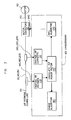
- FIG. 1 is a schematic block diagram of a three-phase power system 10 made in accordance with the disclosed embodiment.
- a three-phase source 20 provides three-phase power over source lines 30, 40, and 50 to a three-phase motor 60 that drives a load 70.
- a processor 80 is configured to sample voltage levels and current levels from the source lines 30, 40, and 50.
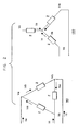
- Figure 2 shows the traditional delta configuration 90 and wye configuration 100 of how the source 20 and motor 60 can be configured in a three-phase power system 10.
- the disclosed embodiment is independent of these configurations and the various combinations thereof.
- Figure 3 illustrates more detail of the disclosed embodiment including digitizers 110 and 120 of processor 80 for digitizing the voltage and current levels, and motor contactors 130 for connecting and disconnecting the motor 60 from the source lines 30, 40, and 50.
- the processor 80 also employs several software algorithms. These comprise a three-phase power factor algorithm 140, a momentary power loss (MPL) algorithm 150, and a surge algorithm 160.
- MPL momentary power loss
- the three-phase source 20 is electrically connected to the motor contactors 130 over the source lines 30, 40, and 50.
- the motor contactors 130 are electrically connected to the three-phase motor 60 over a contactor/motor interface 170 to provide three-phase power to the motor 60.
- the voltage digitizer 110 in the processor 80 is electrically connected to the source lines 30, 40, and 50 over voltage sampling interfaces 180, 190, and 200 to sample voltage levels.
- the current digitizer 120 in the processor 80 is electrically connected to the source lines 30, 40, and 50 over current sampling interfaces 210, 220, and 230 to sample current levels.
- the processor 80 is electrically connected to the motor contactors 130 through a processor/contactor interface 240.
- the positive and negative levels of voltages and currents are measured from the source lines 30, 40, and 50 by the processor 80, maintaining the positive and negative signs of the measured levels.
- the measurements may be taken in various combinations of phase and/or line voltage levels and current levels (see Figure 2 ) such as: first combination: Vab, Vbc, Vca, Ia, Ib, Ic second combination: Va, Vb, Vc, Iab, Ibc, Ica third combination: Vab, Vbc, Vca, Iab, Ibc, Ica fourth combination: Va, Vb, Vc, Ia, Ib, Ic where a, b, and c refer to the three source lines 30, 40, and 50 respectively.
- Va is the phase voltage level on source line a with respect to a voltage reference.
- Vab is the line voltage levels between source lines a and b.
- the three voltage levels and three current levels are sampled and digitized by the processor 80 and used to calculate values of a voltage phasor and values of a current phasor based on the expected geometric arrangement of the magnetic fields produced by the three phases.
- the values of real components (Vr and Ir) and the values of imaginary components (Vi and Ii) of the phasors are given by the following equations based on the 120° separation of the three phases:
- instantaneous power factor cos ⁇
- ⁇ is the spatial or geometric angle by which the current lags the voltage
- the calculation of power is well-known by various calculations but the present invention's calculation of apparent power is unique.
- This equation is the form used by the processor 80 and the algorithm 140 to calculate a value of instantaneous power factor. This equation uses the levels of the voltages and currents and does not directly use trigonometric functions or phase angles. No conversion between wye and delta configurations is needed.
- the processor 80 samples and calculates multiple instances of values of instantaneous power factor at a pre-determined sampling rate over a pre-determined time interval (such as about but preferably not equal to a line cycle) of the three-phase power system. It is preferable that sampling rate not be equal to a line cycle so that sample locations in a line cycle are distributed in relation to a line cycle period but it is also preferable that the interval over which the samples are averaged is an exact multiple of the line cycles both for 50 Hz and 60 Hz. This provides a representative sampling of the instantaneous power factor. In one embodiment of the invention, this pre-determined sampling rate is every 2.5 msec. A line cycle is typically 20 msec or 16.67 msec corresponding to 50 Hz or 60 Hz source power respectively. The algorithm 140 then averages these values of instantaneous power factor to obtain a value of true three-phase power factor.
- a pre-determined sampling rate is every 2.5 msec.
- a line cycle is typically 20 msec or 16.67 msec corresponding to 50
- This value of true three-phase power factor represents the effective power factor of the load the power is being sourced to and has improved insensitivity to any imbalances of the source, line, or load.
- This method of calculating power factor is independent of source and load wye and delta configurations. This method is also independent of the configuration in which the voltage and current levels are measured. For example, they may be measured inside or outside a delta motor with the same results. Time intensive sampling of the voltage and current levels is avoided with this method. A processor with a fast clock and higher cost can, therefore, be avoided.
- These calculations of power factor are highly accurate to give the customer a true sense of the operating point of the system.
- These calculations of power factor can be used in time critical functions such as detection of momentary power loss (MPL) conditions and detection of surge conditions. With this implementation, expensive instrument grade power factor meters can be avoided.
- MPL momentary power loss
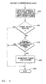
- Figure 4 illustrates how the processor 80 uses values of instantaneous power factor to detect a momentary loss of power (MPL) condition using the MPL algorithm 150.
- the three-phase power system is continuously monitored for an MPL condition.
- the algorithm 140 is called to calculate consecutive instances of values of instantaneous three-phase power factor at a pre-determined sampling rate. In one embodiment of the invention, this sampling rate is every 7.5 msec.
- this sampling rate is every 7.5 msec.
- the values of instantaneous three-phase power factor are checked to determine if they are positive (numerically greater than zero). As long as the instantaneous power factors are positive, an MPL condition does not exist.
- step 270 the algorithm 150 checks to see if the last six consecutive values of instantaneous three-phase power factors have been non-positive (numerically less than or equal to zero). If this is the case, then an MPL condition is detected as shown in step 280. The processor 80 then commands the motor contactors 130 to disconnect power from the motor 60. This will prevent damage from occurring to the motor 60 and/or load 70 due to the MPL condition. A pre-determined time interval elapses before the processor 80 attempts to re-connect source power to the motor 60.
- Using power factor to determine an MPL condition is beneficial because the power factor represents the true state of the motor 60 at any point in time.
- This method is very responsive to power line anomalies, allowing the controls to obtain accurate information quickly.
- This method is also insensitive to DC offsets and non-symmetry of reclosure currents. It is also less sensitive to voltage and current unbalance conditions.
- the voltage and current levels may not be sampled at the same time.
- the up to six inputs could be sampled and stored one at a time with a standard analog-to-digital converter that is subsequently read by the processor, or sampled in some other combination.
- the three-phase power system may be monitored non-continuously for an MPL condition instead of continuously.
- monitoring for an MPL condition may be initiated only when some other condition is detected first, such as, for example, a surge condition.
Landscapes
- Engineering & Computer Science (AREA)
- Power Engineering (AREA)
- Physics & Mathematics (AREA)
- General Physics & Mathematics (AREA)
- Control Of Ac Motors In General (AREA)
Claims (42)
- Vorrichtung zum Erzeugen eines Datenwerts, welcher repräsentativ ist für einen momentanen Dreiphasen-Leistungsfaktor für ein Dreiphasen-Stromversorgungsnetz (10), wobei die Vorrichtung umfasst:eine Auswerte-Einheit (80) zum Abtasten von Spannungswerten und Stromwerten von Stromversorgungsleitern (30, 40, 50) des Dreiphasen-Stromversorgungsnetzes (10), zum Bilden einer Gruppe von Spannungswerten und Stromwerten, wobei die Auswerte-Einheit (80) auf die Gruppe von Spannungswerten und Stromwerten anspricht, zum Erzeugen des Datenwerts, welcher für den momentanen Dreiphasen-Leistungsfaktor repräsentativ ist, wobei die Auswerte-Einheit (80) die Gleichung verwendet:

zum Berechnen eines Werts des momentanen Dreiphasen-Leistungsfaktors, wobei Vr und Ir die Realkomponenten und Vi und Ii die Imaginärkomponenten des Stromzeigers und des Spannungszeigers repräsentieren, welche aus den abgetasteten Stromwerten und Spannungswerten berechnet werden. - Vorrichtung nach Anspruch 1, wobei das Abtasten der Spannungswerte und der Stromwerte von den Stromversorgungsleitern (30, 40, 50) des Dreiphasen-Stromversorgungsnetzes (10) zum Bilden der Gruppe von Spannungswerten und Stromwerten durch die Auswerte-Einheit (80) gleichzeitig ausgeführt wird.
- Vorrichtung nach Anspruch 1, wobei die Auswerte-Einheit (80) auf eine Untergruppe von Spannungswerten der Gruppe von Spannungswerten und Stromwerten anspricht, zum Erzeugen von Datenwerten für Realkomponenten und Imaginärkomponenten, welche für einen Spannungszeiger repräsentativ sind, als ein Teil des Erzeugens des Datenwerts, welcher für den momentanen Dreiphasen-Leistungsfaktor repräsentativ ist.
- Vorrichtung nach Anspruch 3, wobei die Untergruppe von Spannungswerten wenigstens zwei umfasst von:einem Spannungswert der ersten Phase, welcher von einem ersten Versorgungsleiter (30) der Stromversorgungsleitung abgetastet wird, relativ zu einer gemeinsamen Spannungsreferenz;einem Spannungswert der zweiten Phase, welcher von einem zweiten Versorgungsleiter (40) der Stromversorgungsleitung abgetastet wird, relativ zu einer gemeinsamen Spannungsreferenz; undeinem Spannungswert der dritten Phase, welcher von einem dritten Versorgungsleiter (50) der Stromversorgungsleitung abgetastet wird, relativ zu einer gemeinsamen Spannungsreferenz.
- Vorrichtung nach Anspruch 4, wobei die Untergruppe von Spannungswerten umfasst:einen Spannungswert der ersten Phase, welcher von einem ersten Versorgungsleiter (30) der Stromversorgungsleitung abgetastet wird, relativ zu einer gemeinsamen Spannungsreferenz;einen Spannungswert der zweiten Phase, welcher von einem zweiten Versorgungsleiter (40) der Stromversorgungsleitung abgetastet wird, relativ zu einer gemeinsamen Spannungsreferenz; undeinen Spannungswert der dritten Phase, welcher von einem dritten Versorgungsleiter (50) der Stromversorgungsleitung abgetastet wird, relativ zu einer gemeinsamen Spannungsreferenz.
- Vorrichtung nach Anspruch 3, wobei die Untergruppe von Spannungswerten wenigstens zwei umfasst von:einem Spannungswert des ersten Leiters, welcher von einem ersten Versorgungsleiter (30) abgetastet wird, relativ zu einem zweiten Versorgungsleiter der Stromversorgungsleitung;einem Spannungswert des zweiten Leiters, welcher von dem zweiten Versorgungsleiter (40) abgetastet wird, relativ zu einem dritten Versorgungsleiter der Stromversorgungsleitung; undeinem Spannungswert des dritten Leiters, welcher von dem dritten Versorgungsleiter (50) abgetastet wird, relativ zu dem ersten Versorgungsleiter der Stromversorgungsleitung.
- Vorrichtung nach Anspruch 6, wobei die Untergruppe von Spannungswerten umfasst:einen Spannungswert des ersten Leiters, welcher von einem ersten versorgungsleiter (30) abgetastet wird, relativ zu einem zweiten Versorgungsleiter der Stromversorgungsleitung;einen Spannungswert des zweiten Leiters, welcher von dem zweiten Versorgungsleiter (40) abgetastet wird, relativ zu einem dritten Versorgungsleiter der Stromversorgungsleitung; undeinen Spannungswert des dritten Leiters, welcher von dem dritten Versorgungsleiter (50) abgetastet wird, relativ zu dem ersten Versorgungsleiter der Stromversorgungsleitung.
- Vorrichtung nach Anspruch 1, wobei die Auswerte-Einheit (80) auf eine Untergruppe von Stromwerten der Gruppe von Spannungswerten und Stromwerten anspricht, zum Erzeugen von Datenwerten für Realkomponenten und Imaginärkomponenten, welche für einen Stromzeiger als ein Teil des Erzeugens des Datenwerts repräsentativ sind, welcher für den momentanen Dreiphasen-Leistungsfaktor repräsentativ ist.
- Vorrichtung nach Anspruch 8, wobei die Untergruppe von Stromwerten wenigstens zwei umfasst von:einem Stromwert der ersten Phase, welcher von einem ersten Versorgungsleiter (30) der Stromversorgungsleitung abgetastet wird;einem Stromwert der zweiten Phase, welcher von einem zweiten Versorgungsleiter (40) der Stromversorgungsleitung abgetastet wird; undeinem Stromwert der dritten Phase, welcher von einem dritten versorgungsleiter (50) der der Stromversorgungsleitung abgetastet wird.
- Vorrichtung nach Anspruch 9, wobei die Untergruppe von Stromwerten umfasst:einen Stromwert der ersten Phase, welcher von einem ersten Versorgungsleiter (30) der Stromversorgungsleitung abgetastet wird;einen Stromwert der zweiten Phase, welcher von einem zweiten Versorgungsleiter (40) der Stromversorgungsleitung abgetastet wird;einen Stromwert der dritten Phase, welcher von einem dritten Versorgungsleiter (50) der Stromversorgungsleitung abgetastet wird.
- Vorrichtung nach Anspruch 8, wobei die Untergruppe von Stromwerten wenigstens zwei umfasst von:einem Stromwert des ersten Leiters, welcher von einem ersten Versorgungsleiter (30) der Stromversorgungsleitung abgetastet wird;einem Stromwert des zweiten Leiters, welcher von einem zweiten Versorgungsleiter (40) der Stromversorgungsleitung abgetastet wird; undeinem Stromwert des dritten Leiters, welcher von einem dritten Versorgungsleiter (50) der Stromversorgungsleitung abgetastet wird.
- Vorrichtung nach Anspruch 11, wobei die Untergruppe von Stromwerten umfasst:einen Stromwert des ersten Leiters, welcher von einem ersten Versorgungsleiter (30) der Stromversorgungsleitung abgetastet wird;einen Stromwert des zweiten Leiters, welcher von einem zweiten Versorgungsleiter (40) der Stromversorgungsleitung abgetastet wird; undeinen Stromwert des dritten Leiters, welcher von einem dritten Versorgungsleiter (50) der Stromversorgungsleitung abgetastet wird.
- Vorrichtung nach Anspruch 1, ferner umfassend die Auswerte-Einheit (80), welche mehrere Gruppen von Spannungs- und Stromwerten abtastet, bei einer vorbestimmten Abtastrate, über ein vorbestimmtes Zeitintervall, zum Erzeugen einer Gruppe von Datenwerten momentaner Dreiphasen-Leistungsfaktoren.
- Vorrichtung nach Anspruch 13, wobei die Abtastrate derart ausgewählt ist, dass die Zeitpunkte zum Abtasten in der Schwingungsperiode eines Leiters eingeteilt sind, und dass ein repräsentatives Abtasten der Werte momentaner Leistungsfaktoren gegeben ist.
- Vorrichtung nach Anspruch 13, wobei die Auswerte-Einheit (80) auf die Gruppe von Datenwerten momentaner Dreiphasen-Leistungsfaktoren anspricht, zum Erzeugen eines Datenwerts eines True-Power-Factor-Werts des Dreiphasen-Leistungsfaktors, durch Filtern der Gruppe von Datenwerten momentaner Dreiphasen-Leistungsfaktoren.
- Vorrichtung nach Anspruch 1, wobei die Auswerte-Einheit (80) zum Abtasten mehrerer Gruppen von Spannungswerten und Stromwerten geeignet ist, bei einer vorbestimmten Abtastrate, zum fortlaufenden Erzeugen entsprechender mehrerer Datenwerte momentaner Dreiphasen-Leistungsfaktoren.
- Vorrichtung nach Anspruch 16, wobei die Auswerte-Einheit (80) zum fortlaufenden Prüfen geeignet ist, ob jeder von einer vorbestimmten Anzahl aufeinanderfolgender aktueller Datenwerte für die entsprechenden mehreren Datenwerte momentaner Dreiphasen-Leistungsfaktoren kleiner oder gleich null, d.h. nicht positiv, ist.
- Vorrichtung nach Anspruch 17, wobei die Auswerte-Einheit (80) zum Erklären eines Vorliegens eines Zustands eines momentanen Stromausfalls geeignet ist, wenn jeder von der vorbestimmten Anzahl aufeinanderfolgender aktueller Datenwerte für die entsprechenden mehreren Datenwerte momentaner Dreiphasen-Leistungsfaktoren kleiner oder gleich null, d.h. nicht positiv, ist.
- Vorrichtung nach Anspruch 18, wobei die Auswerte-Einheit (80) zum Befehlen geeignet ist, dass eine Last an dem Dreiphasen-Stromversorgungsnetz (10) wenigstens temporär von den Strom-Zuleitungen (30, 40, 50) getrennt wird, wenn die Auswerte-Einheit (80) das Vorliegen des Zustands eines momentanen Stromausfalls erklärt.
- Verfahren zum Erzeugen eines Datenwerts, welcher für einen momentanen Dreiphasen-Leistungsfaktor in einem Dreiphasen-Stromversorgungsnetz repräsentativ ist, wobei das Verfahren umfasst:Abtasten von Spannungswerten und Stromwerten von Stromversorgungsleitern (30, 40, 50) des Dreiphasen-Stromversorgungsnetzes (10) zum Bilden einer Gruppe von Spannungswerten und Stromwerten; undErzeugen des Datenwerts, welcher für den momentanen Dreiphasen-Leistungsfaktor repräsentativ ist, in Antwort auf die Gruppe von Spannungswerten und Stromwerten, auf Basis der Gleichung:

zum Berechnen eines Werts des momentanen Dreiphasen-Leistungsfaktors, wobei Vr und Ir die Realkomponenten und Vi und Ii die Imaginärkomponenten des Stromzeigers und des Spannungszeigers repräsentieren, welche aus den abgetasteten Stromwerten und Spannungswerten berechnet werden. - Verfahren nach Anspruch 20, wobei das Abtasten der Spannungswerte und der Stromwerte von den Stromversorgungsleitern des Dreiphasen-Stromnetzes (10) zum Bilden der Gruppe von Spannungswerten und Stromwerten gleichzeitig ausgeführt wird.
- Verfahren nach Anspruch 20, ferner umfassend Erzeugen von Datenwerten für Realkomponenten und Imaginärkomponenten, welche für einen Spannungszeiger repräsentativ sind, in Antwort auf eine Untergruppe von Spannungswerten der Gruppe von Spannungswerten und Stromwerten, als ein Teil des Erzeugens des Datenwerts, welcher für den momentanen Dreiphasen-Leistungsfaktor repräsentativ ist.
- Verfahren nach Anspruch 22, wobei die Untergruppe von Spannungswerten wenigstens zwei umfasst von:einem Spannungswert der ersten Phase, welcher von einem ersten Versorgungsleiter (30) der Stromversorgungsleitung abgetastet wird, relativ zu einer gemeinsamen Spannungsreferenz;einem Spannungswert der zweiten Phase, welcher von einem zweiten Versorgungsleiter (40) der Stromversorgungsleitung abgetastet wird, relativ zu einer gemeinsamen Spannungsreferenz; undeinem Spannungswert der dritten Phase, welcher von einem dritten Versorgungsleiter (50) der Stromversorgungsleitung abgetastet wird, relativ zu einer gemeinsamen Spannungsreferenz.
- Verfahren nach Anspruch 23, wobei die Untergruppe von Spannungswerten umfasst:einen Spannungswert der ersten Phase, welcher von einem ersten Versorgungsleiter (30) der Stromversorgungsleitung abgetastet wird, relativ zu einer gemeinsamen Spannungsreferenz;einen spannungswert der zweiten Phase, welcher von einem zweiten Versorgungsleiter (40) der Stromversorgungsleitung abgetastet wird, relativ zu einer gemeinsamen Spannungsreferenz; undeinen Spannungswert der dritten Phase, welcher von einem dritten Versorgungsleiter (50) der Stromversorgungsleitung abgetastet wird, relativ zu einer gemeinsamen Spannungsreferenz.
- Verfahren nach Anspruch 22, wobei die Untergruppe von Spannungswerten wenigstens zwei umfasst von:einem Spannungswert des ersten Leiters, welcher von einem ersten Versorgungsleiter (30) abgetastet wird, relativ zu einem zweiten Versorgungsleiter der Stromversorgungsleitung;einem Spannungswert des zweiten Leiters, welcher von dem zweiten Versorgungsleiter (40) abgetastet wird, relativ zu einem dritten Versorgungsleiter der Stromversorgungsleitung; undeinem Spannungswert des dritten Leiters, welcher von dem dritten versorgungsleiter (50) abgetastet wird, relativ zu dem ersten Versorgungsleiter der Strom-Stromversorgungsleitung.
- Verfahren nach Anspruch 25, wobei die Untergruppe von Spannungswerten umfasst:einen Spannungswert des ersten Leiters, welcher von einem ersten Versorgungsleiter (30) abgetastet wird, relativ zu einem zweiten Versorgungsleiter der Stromversorgungsleitung;einen Spannungswert des zweiten Leiters, welcher von dem zweiten Versorgungsleiter (40) abgetastet wird, relativ zu einem dritten Versorgungsleiter der Stromversorgungsleitung; undeinen Spannungswert des dritten Leiters, welcher von dem dritten Versorgungsleiter (50) abgetastet wird, relativ zu dem ersten Versorgungsleiter der Stromversorgungsleitung.
- Verfahren nach Anspruch 20, ferner umfassend Erzeugen von Datenwerten für Realkomponenten und Imaginärkomponenten, welche für einen Stromzeiger repräsentativ sind, in Antwort auf eine Untergruppe von Stromwerten der Gruppe von Spannungswerten und Stromwerten, als ein Teil des Erzeugens des Datenwerts, welcher für den momentanen Dreiphasen-Leistungsfaktor repräsentativ ist.
- Verfahren nach Anspruch 27, wobei die Untergruppe von Stromwerten wenigstens zwei umfasst von:einem Stromwert der ersten Phase, welcher von einem ersten versorgungsleiter (30) der Stromversorgungsleitung abgetastet wird;einem Stromwert der zweiten Phase, welcher von einem zweiten versorgungsleiter (40) der Stromversorgungsleitung abgetastet wird; undeinem Stromwert der dritten Phase, welcher von einer dritten Versorgungsleiter (50) der Stromversorgungsleitung abgetastet wird.
- Verfahren nach Anspruch 28, wobei die Untergruppe von Stromwerten umfasst:einen Stromwert der ersten Phase, welcher von einem ersten Versorgungsleiter (30) der Stromversorgungsleitung abgetastet wird;einen Stromwert der zweiten Phase, welcher von einem zweiten Versorgungsleiter (40) der Stromversorgungsleitung abgetastet wird;einen Stromwert der dritten Phase, welcher von einem dritten Versorgungsleiter (50) der Stromversorgungsleitung abgetastet wird.
- Verfahren nach Anspruch 27, wobei die Untergruppe von Stromwerten wenigstens zwei umfasst von:einem Stromwert des ersten Leiters, welcher von einem ersten Versorgungsleiter (30) der Stromversorgungsleitung abgetastet wird;einem Stromwert des zweiten Leiters, welcher von einem zweiten Versorgungsleiter (40) der Stromversorgungsleitung abgetastet wird; undeinem Stromwert des dritten Leiters, welcher von einem dritten Versorgungsleiter (50) der Stromversorgungsleitung abgetastet wird.
- Verfahren nach Anspruch 30, wobei die Untergruppe von Stromwerten umfasst:einen Stromwert des ersten Leiters, welcher von einem ersten Versorgungsleiter (30) der Stromversorgungsleitung abgetastet wird;einen Stromwert des zweiten Leiters, welcher von einem zweiten Versorgungsleiter (40) der Stromversorgungsleitung abgetastet wird; undeinen Stromwert des dritten Leiters, welcher von einem dritten versorgungsleiter (50) der Stromversorgungsleitung abgetastet wird.
- Verfahren nach Anspruch 20, ferner umfassend Abtasten mehrerer Gruppen von Spannungs- und Stromwerten, bei einer vorbestimmten Abtastrate, über ein vorbestimmtes Zeitintervall, zum Erzeugen einer Gruppe von Datenwerten momentaner Dreiphasen-Leistungsfaktoren.
- Verfahren nach Anspruch 32, wobei die Abtastrate derart ausgewählt wird, dass die Zeitpunkte zum Abtasten in der Schwingungsperiode eines Leiters eingeteilt sind, und dass ein repräsentatives Abtasten der Werte momentaner Leistungsfaktoren gegeben ist.
- Verfahren nach Anspruch 32, ferner umfassend Erzeugen eines Datenwerts eines True-Power-Factor-Werts des Dreiphasen-Leistungsfaktors, durch Filtern der Gruppe von Datenwerten momentaner Dreiphasen-Leistungsfaktoren.
- Verfahren nach Anspruch 20, ferner umfassend Abtasten mehrerer Gruppen von Spannungswerten und Stromwerte, bei einer vorbestimmten Abtastrate, zum fortlaufenden Erzeugen entsprechender mehrerer Datenwerte momentaner Dreiphasen-Leistungsfaktoren.
- Verfahren nach Anspruch 35, ferner umfassend fortlaufendes Prüfen, ob jeder von einer vorbestimmten Anzahl aufeinanderfolgender aktueller Datenwerte für die entsprechenden mehreren Datenwerte momentaner Dreiphasen-Leistungsfaktoren kleiner oder gleich null, d.h. nicht positiv, ist.
- Verfahren nach Anspruch 36, ferner umfassend Erklären eines vorliegens eines Zustands eines momentanen Stromausfalls, wenn jeder von der vorbestimmten Anzahl aufeinanderfolgender neuester Datenwerte für die entsprechenden mehreren Datenwerte momentaner Dreiphasen-Leistungsfaktoren kleiner oder gleich null, d.h. nicht positiv, ist.
- Verfahren nach Anspruch 37, ferner umfassend Befehlen, dass eine Last an dem Dreiphasen-Stromversorgungsnetz (10) wenigstens temporär von den Stromversorgungsleitungen getrennt wird, wenn das Vorliegen des Zustands eines momentanen Stromausfalls erklärt wird.
- Verfahren nach Anspruch 20, wobei der Schritt des Abtastens die Schritte umfasst:Bestimmen von drei Gruppen von Strömen, welche jeweils drei Motorphasen zugeordnet sind;Bestimmen von drei Gruppen von Spannungen, welche jeweils drei Motorphasen zugeordnet sind, und wobei der Schritt des Erzeugens den Schritt umfasst:Berechnen von Stromzeigern und Spannungszeigern aus den Gruppen von Strömen und den Gruppen von Spannungen; undBestimmen eines momentanen Leistungsfaktors aus den berechneten Stromzeigern und Spannungszeigern.
- Verfahren nach Anspruch 39, umfassend den weiteren Schritt des mittelns des momentanen Leistungsfaktors über eine Schwingungsperiode eines Leiters, zum Bestimmen des Leistungsfaktors.
- Vorrichtung nach Anspruch 1, ferner umfassend:Mittel zum Bestimmen von drei Gruppen von Strömen, welche jeweils drei Motorphasen zugeordnet sind;Mittel zum Bestimmen von drei Gruppen von Spannungen, welche jeweils drei Motorphasen zugeordnet sind;Mittel zum Berechnen von Stromzeigern und Spannungszeigern aus den Gruppen von Strömen und den Gruppen von Spannungen; undMittel zum Bestimmen eines momentanen Leistungsfaktors aus den berechneten Stromzeigern und Spannungszeigern.
- Anordnung nach Anspruch 41, ferner umfassend Mittel zum Mitteln des momentanen Leistungsfaktors über eine Schwingungsperiode eines Leiters zum Bestimmen des Leistungsfaktors.
Applications Claiming Priority (3)
| Application Number | Priority Date | Filing Date | Title |
|---|---|---|---|
| US09/976,194 US20030078742A1 (en) | 2001-10-11 | 2001-10-11 | Determination and applications of three-phase power factor |
| US976194 | 2001-10-11 | ||
| PCT/US2002/027162 WO2003031996A1 (en) | 2001-10-11 | 2002-08-26 | Apparatus and method for calculating of three-phase power factor |
Publications (2)
| Publication Number | Publication Date |
|---|---|
| EP1435002A1 EP1435002A1 (de) | 2004-07-07 |
| EP1435002B1 true EP1435002B1 (de) | 2011-10-05 |
Family
ID=25523844
Family Applications (1)
| Application Number | Title | Priority Date | Filing Date |
|---|---|---|---|
| EP02761502A Expired - Lifetime EP1435002B1 (de) | 2001-10-11 | 2002-08-26 | Vorrichtung und verfahren zur berechnung des dreiphasen-leistungsfaktors |
Country Status (5)
| Country | Link |
|---|---|
| US (1) | US20030078742A1 (de) |
| EP (1) | EP1435002B1 (de) |
| CN (1) | CN100354635C (de) |
| CA (1) | CA2458178A1 (de) |
| WO (1) | WO2003031996A1 (de) |
Families Citing this family (36)
| Publication number | Priority date | Publication date | Assignee | Title |
|---|---|---|---|---|
| US7102343B1 (en) * | 2003-03-31 | 2006-09-05 | Invensys Systems, Inc. | Methods and systems having multiple cooperating transformers |
| US7173345B2 (en) * | 2003-09-15 | 2007-02-06 | Rockwell Automation Technologies, Inc. | Multi-function integrated automation cable connector system and method |
| US7412842B2 (en) | 2004-04-27 | 2008-08-19 | Emerson Climate Technologies, Inc. | Compressor diagnostic and protection system |
| US7038423B2 (en) * | 2004-05-07 | 2006-05-02 | Bay Controls, Inc. | Apparatus and method for ride through for AC induction motors |
| US7216049B2 (en) * | 2004-06-23 | 2007-05-08 | Whirlpool Corporation | Method for calibrating current offset and filtering bad data in a system that detects power output |
| US7275377B2 (en) | 2004-08-11 | 2007-10-02 | Lawrence Kates | Method and apparatus for monitoring refrigerant-cycle systems |
| US8590329B2 (en) | 2004-12-22 | 2013-11-26 | Johnson Controls Technology Company | Medium voltage power controller |
| US7353662B2 (en) * | 2004-12-22 | 2008-04-08 | York International Corporation | Medium voltage starter for a chiller unit |
| US8590325B2 (en) | 2006-07-19 | 2013-11-26 | Emerson Climate Technologies, Inc. | Protection and diagnostic module for a refrigeration system |
| US20080216494A1 (en) | 2006-09-07 | 2008-09-11 | Pham Hung M | Compressor data module |
| US20090037142A1 (en) | 2007-07-30 | 2009-02-05 | Lawrence Kates | Portable method and apparatus for monitoring refrigerant-cycle systems |
| US8393169B2 (en) | 2007-09-19 | 2013-03-12 | Emerson Climate Technologies, Inc. | Refrigeration monitoring system and method |
| US8160827B2 (en) * | 2007-11-02 | 2012-04-17 | Emerson Climate Technologies, Inc. | Compressor sensor module |
| AU2012241185B2 (en) * | 2007-11-02 | 2014-07-10 | Emerson Climate Technologies, Inc. | Compressor Sensor Module |
| US9140728B2 (en) * | 2007-11-02 | 2015-09-22 | Emerson Climate Technologies, Inc. | Compressor sensor module |
| US8405382B2 (en) * | 2009-10-19 | 2013-03-26 | Eaton Corporation | Selectable delta or wye voltage configuration for power measurement |
| US9825574B2 (en) | 2010-05-11 | 2017-11-21 | Carrier Corporation | Chiller motor control system |
| EP2681497A4 (de) | 2011-02-28 | 2017-05-31 | Emerson Electric Co. | Hvac-überwachung und diagnose für haushaltsanwendungen |
| CN102801145A (zh) * | 2011-05-24 | 2012-11-28 | 深圳市万禧节能科技有限公司 | 系统节电器 |
| US8964338B2 (en) | 2012-01-11 | 2015-02-24 | Emerson Climate Technologies, Inc. | System and method for compressor motor protection |
| US9480177B2 (en) | 2012-07-27 | 2016-10-25 | Emerson Climate Technologies, Inc. | Compressor protection module |
| US9310439B2 (en) | 2012-09-25 | 2016-04-12 | Emerson Climate Technologies, Inc. | Compressor having a control and diagnostic module |
| CN103852640B (zh) * | 2012-12-04 | 2016-05-04 | 中国北车股份有限公司 | 电网电压相位计算方法、装置及单相脉冲宽度调制整流器 |
| US20140230463A1 (en) * | 2013-02-15 | 2014-08-21 | GM Global Technology Operations LLC | Method for controlling a compressor of a thermal storage heat pump system |
| NZ713115A (en) * | 2013-03-13 | 2019-06-28 | Franklin Control Systems Llc | Apparatus, system, and/or method for intelligent motor protection and/or control |
| US9551504B2 (en) | 2013-03-15 | 2017-01-24 | Emerson Electric Co. | HVAC system remote monitoring and diagnosis |
| WO2014144446A1 (en) | 2013-03-15 | 2014-09-18 | Emerson Electric Co. | Hvac system remote monitoring and diagnosis |
| US9803902B2 (en) | 2013-03-15 | 2017-10-31 | Emerson Climate Technologies, Inc. | System for refrigerant charge verification using two condenser coil temperatures |
| CA2908362C (en) | 2013-04-05 | 2018-01-16 | Fadi M. Alsaleem | Heat-pump system with refrigerant charge diagnostics |
| PL2843427T3 (pl) * | 2013-09-02 | 2019-03-29 | Advanced Energy Industries Gmbh | Wyznaczanie wielkości elektrycznych w obwodach wielobocznych i gwiazdowych |
| US9982930B2 (en) * | 2014-02-05 | 2018-05-29 | Lennox Industries Inc. | System for controlling operation of an HVAC system |
| CN103926449B (zh) * | 2014-04-24 | 2016-11-02 | 江苏省电力公司常州供电公司 | 电力电缆接地电流的自适应监测方法 |
| CN109444534A (zh) * | 2016-03-02 | 2019-03-08 | 中国人民解放军91663部队 | 带有计量接口的功率表的原位计量方法 |
| WO2017147838A1 (en) * | 2016-03-03 | 2017-09-08 | The University Of Hong Kong | Power measurement system |
| CN116699235B (zh) * | 2023-08-08 | 2023-11-07 | 安徽融兆智能有限公司 | 一种具有异常检测功能的三相三线电能表 |
| US20250283955A1 (en) * | 2024-03-06 | 2025-09-11 | Eaton Intelligent Power Limited | Electric circuit health indicator and efficiency improvement device and method |
Family Cites Families (19)
| Publication number | Priority date | Publication date | Assignee | Title |
|---|---|---|---|---|
| GB1559649A (en) * | 1976-09-27 | 1980-01-23 | Waurick & Ass B G | Methods of and devices for measuring ac power |
| US4333046A (en) * | 1979-08-15 | 1982-06-01 | The Scott & Fetzer Company | Power factor control of a three-phase induction motor |
| US4317076A (en) * | 1980-03-20 | 1982-02-23 | Hilscher-Clarke Electric Co. | Power factor control system |
| ES2040012T3 (es) * | 1989-12-14 | 1993-10-01 | Landis & Gyr Business Support Ag | Disposicion para la determinacion de valores de magnitudes electricas, que se pueden deducir de valores de medida de al menos dos magnitudes electricas de entrada de la disposicion. |
| US5495384A (en) * | 1990-04-02 | 1996-02-27 | Square D Company | Apparatus and method for detecting a fault in a distributed line network |
| US5485393A (en) * | 1990-08-30 | 1996-01-16 | Metricom, Inc. | Method and apparatus for measuring electrical parameters using a differentiating current sensor and a digital integrator |
| US5349676A (en) * | 1991-02-11 | 1994-09-20 | General Electric Company | Data acquisition systems with programmable bit-serial digital signal processors |
| US5229713A (en) * | 1991-04-25 | 1993-07-20 | General Electric Company | Method for determining electrical energy consumption |
| US5521482A (en) * | 1993-06-29 | 1996-05-28 | Liberty Technologies, Inc. | Method and apparatus for determining mechanical performance of polyphase electrical motor systems |
| US5519300A (en) * | 1993-06-29 | 1996-05-21 | Liberty Technologies, Inc. | Method and apparatus for analysis of polyphase electrical motor systems |
| US5434738A (en) * | 1993-07-12 | 1995-07-18 | American Standard Inc. | Apparatus and method for protecting induction motors from momentary power loss |
| US5465040A (en) * | 1993-09-23 | 1995-11-07 | Yasotornrat; Hemtong | Three phase power factor correction device and method |
| US5469045A (en) * | 1993-12-07 | 1995-11-21 | Dove; Donald C. | High speed power factor controller |
| US5528136A (en) * | 1994-10-06 | 1996-06-18 | Teradyne, Inc. | VLSI component tester with average current measuring capability |
| US5673196A (en) * | 1995-11-30 | 1997-09-30 | General Electric Company | Vector electricity meters and associated vector electricity metering methods |
| US6128583A (en) * | 1996-05-20 | 2000-10-03 | Crane Nuclear, Inc. | Motor stator condition analyzer |
| US20010035690A1 (en) * | 1997-12-01 | 2001-11-01 | Kato Keith G. | Magneto-cumulative generator performance by using variable bitter coil-type stator windings |
| US6094952A (en) * | 1998-01-02 | 2000-08-01 | Sargent & Greenleaf, Inc. | Dead bolt combination lock with integrated re-locking features |
| US6160374A (en) * | 1999-08-02 | 2000-12-12 | General Motors Corporation | Power-factor-corrected single-stage inductive charger |
-
2001
- 2001-10-11 US US09/976,194 patent/US20030078742A1/en not_active Abandoned
-
2002
- 2002-08-26 CN CNB028200772A patent/CN100354635C/zh not_active Expired - Lifetime
- 2002-08-26 EP EP02761502A patent/EP1435002B1/de not_active Expired - Lifetime
- 2002-08-26 CA CA002458178A patent/CA2458178A1/en not_active Abandoned
- 2002-08-26 WO PCT/US2002/027162 patent/WO2003031996A1/en not_active Ceased
Also Published As
| Publication number | Publication date |
|---|---|
| CA2458178A1 (en) | 2003-04-17 |
| WO2003031996A1 (en) | 2003-04-17 |
| US20030078742A1 (en) | 2003-04-24 |
| EP1435002A1 (de) | 2004-07-07 |
| CN100354635C (zh) | 2007-12-12 |
| CN1568428A (zh) | 2005-01-19 |
Similar Documents
| Publication | Publication Date | Title |
|---|---|---|
| EP1435002B1 (de) | Vorrichtung und verfahren zur berechnung des dreiphasen-leistungsfaktors | |
| US5805395A (en) | Half-cycle summation V/Hz relay for generator and transformer over-excitation protection | |
| EP2482411B1 (de) | Laufwerkfehlerschutz | |
| US5671112A (en) | Digital integrator V/Hz relay for generator and transformer over-excitation protection | |
| EP2905630B1 (de) | Fehlererkennung in bürstenlosen Erregern | |
| EP2309280B1 (de) | Erdfehlermessgerät | |
| US8791715B2 (en) | Method for monitoring a controller of a three-phase electric motor and/or the electric motor | |
| WO2013004285A1 (en) | System for detecting internal winding faults of a synchronous generator, computer program product and method | |
| EP2178185B1 (de) | Motorgetriebeerdschlusserkennung | |
| EP3611836B1 (de) | Induktionsmotor-langstartschutz | |
| US12140637B2 (en) | Motor winding fault diagnosis | |
| Kral et al. | Model-based detection of rotor faults without rotor position sensor-the sensorless Vienna monitoring method | |
| EP4199346B1 (de) | Fehlerdiagnose für motorwicklung | |
| JP2980698B2 (ja) | インバータ装置 | |
| EP2337216B1 (de) | Mehrzweck-Permanentmagnete für einen Geschwindigkeitssensor und einen Generator | |
| JP2008032633A (ja) | 電気設備の絶縁監視装置およびその方法 | |
| CN115000975B (zh) | 配电系统的无功补偿方法及配电系统 | |
| CN110554313A (zh) | 一种电流故障检测方法及装置 | |
| JPH11174105A (ja) | 交流フィルタ回路の異常検出装置 | |
| JPH06165364A (ja) | 交流電源の欠相検出方法 | |
| GB2409905A (en) | Plausibility check of an electric three-phase system | |
| JPH08262085A (ja) | 3相不平衡検出装置及び電力変換装置 | |
| HU192855B (en) | Method and circuit arrangement for evaluation of instantaneous value of phase-quantities of poly-phase circuit without time delay |
Legal Events
| Date | Code | Title | Description |
|---|---|---|---|
| PUAI | Public reference made under article 153(3) epc to a published international application that has entered the european phase |
Free format text: ORIGINAL CODE: 0009012 |
|
| 17P | Request for examination filed |
Effective date: 20040324 |
|
| AK | Designated contracting states |
Kind code of ref document: A1 Designated state(s): AT BE BG CH CY CZ DE DK EE ES FI FR GB GR IE IT LI LU MC NL PT SE SK TR |
|
| AX | Request for extension of the european patent |
Extension state: AL LT LV MK RO SI |
|
| RIN1 | Information on inventor provided before grant (corrected) |
Inventor name: VOGEL, RICHARD, L. Inventor name: MURRY, MICHAEL, W. Inventor name: SHEPECK, MATTHEW, A. Inventor name: VANDERZEE, JOEL, C. |
|
| RIN1 | Information on inventor provided before grant (corrected) |
Inventor name: SHEPECK, MATTHEW, A. Inventor name: MURRY, MICHAEL, W. Inventor name: VANDERZEE, JOEL, C. Inventor name: VOGEL, RICHARD, L. |
|
| 17Q | First examination report despatched |
Effective date: 20070705 |
|
| REG | Reference to a national code |
Ref country code: DE Ref legal event code: 8566 |
|
| RAP1 | Party data changed (applicant data changed or rights of an application transferred) |
Owner name: TRANE INTERNATIONAL INC. |
|
| GRAP | Despatch of communication of intention to grant a patent |
Free format text: ORIGINAL CODE: EPIDOSNIGR1 |
|
| GRAS | Grant fee paid |
Free format text: ORIGINAL CODE: EPIDOSNIGR3 |
|
| GRAA | (expected) grant |
Free format text: ORIGINAL CODE: 0009210 |
|
| AK | Designated contracting states |
Kind code of ref document: B1 Designated state(s): FR GB |
|
| REG | Reference to a national code |
Ref country code: GB Ref legal event code: FG4D |
|
| PLBE | No opposition filed within time limit |
Free format text: ORIGINAL CODE: 0009261 |
|
| STAA | Information on the status of an ep patent application or granted ep patent |
Free format text: STATUS: NO OPPOSITION FILED WITHIN TIME LIMIT |
|
| 26N | No opposition filed |
Effective date: 20120706 |
|
| REG | Reference to a national code |
Ref country code: FR Ref legal event code: PLFP Year of fee payment: 15 |
|
| REG | Reference to a national code |
Ref country code: FR Ref legal event code: PLFP Year of fee payment: 16 |
|
| REG | Reference to a national code |
Ref country code: FR Ref legal event code: PLFP Year of fee payment: 17 |
|
| PGFP | Annual fee paid to national office [announced via postgrant information from national office to epo] |
Ref country code: FR Payment date: 20210722 Year of fee payment: 20 |
|
| PGFP | Annual fee paid to national office [announced via postgrant information from national office to epo] |
Ref country code: GB Payment date: 20210720 Year of fee payment: 20 |
|
| REG | Reference to a national code |
Ref country code: GB Ref legal event code: PE20 Expiry date: 20220825 |
|
| PG25 | Lapsed in a contracting state [announced via postgrant information from national office to epo] |
Ref country code: GB Free format text: LAPSE BECAUSE OF EXPIRATION OF PROTECTION Effective date: 20220825 |