EP1434914B1 - Elevator belt assembly with noise reducing groove arrangement - Google Patents
Elevator belt assembly with noise reducing groove arrangement Download PDFInfo
- Publication number
- EP1434914B1 EP1434914B1 EP02761752A EP02761752A EP1434914B1 EP 1434914 B1 EP1434914 B1 EP 1434914B1 EP 02761752 A EP02761752 A EP 02761752A EP 02761752 A EP02761752 A EP 02761752A EP 1434914 B1 EP1434914 B1 EP 1434914B1
- Authority
- EP
- European Patent Office
- Prior art keywords
- grooves
- jacket
- belt
- assembly
- cords
- Prior art date
- Legal status (The legal status is an assumption and is not a legal conclusion. Google has not performed a legal analysis and makes no representation as to the accuracy of the status listed.)
- Expired - Lifetime
Links
Images


Classifications
-
- D—TEXTILES; PAPER
- D07—ROPES; CABLES OTHER THAN ELECTRIC
- D07B—ROPES OR CABLES IN GENERAL
- D07B5/00—Making ropes or cables from special materials or of particular form
- D07B5/005—Making ropes or cables from special materials or of particular form characterised by their outer shape or surface properties
- D07B5/006—Making ropes or cables from special materials or of particular form characterised by their outer shape or surface properties by the properties of an outer surface polymeric coating
-
- F—MECHANICAL ENGINEERING; LIGHTING; HEATING; WEAPONS; BLASTING
- F16—ENGINEERING ELEMENTS AND UNITS; GENERAL MEASURES FOR PRODUCING AND MAINTAINING EFFECTIVE FUNCTIONING OF MACHINES OR INSTALLATIONS; THERMAL INSULATION IN GENERAL
- F16G—BELTS, CABLES, OR ROPES, PREDOMINANTLY USED FOR DRIVING PURPOSES; CHAINS; FITTINGS PREDOMINANTLY USED THEREFOR
- F16G1/00—Driving-belts
-
- D—TEXTILES; PAPER
- D07—ROPES; CABLES OTHER THAN ELECTRIC
- D07B—ROPES OR CABLES IN GENERAL
- D07B1/00—Constructional features of ropes or cables
- D07B1/16—Ropes or cables with an enveloping sheathing or inlays of rubber or plastics
- D07B1/162—Ropes or cables with an enveloping sheathing or inlays of rubber or plastics characterised by a plastic or rubber enveloping sheathing
-
- D—TEXTILES; PAPER
- D07—ROPES; CABLES OTHER THAN ELECTRIC
- D07B—ROPES OR CABLES IN GENERAL
- D07B1/00—Constructional features of ropes or cables
- D07B1/22—Flat or flat-sided ropes; Sets of ropes consisting of a series of parallel ropes
-
- D—TEXTILES; PAPER
- D07—ROPES; CABLES OTHER THAN ELECTRIC
- D07B—ROPES OR CABLES IN GENERAL
- D07B2201/00—Ropes or cables
- D07B2201/20—Rope or cable components
- D07B2201/2083—Jackets or coverings
- D07B2201/2087—Jackets or coverings being of the coated type
-
- D—TEXTILES; PAPER
- D07—ROPES; CABLES OTHER THAN ELECTRIC
- D07B—ROPES OR CABLES IN GENERAL
- D07B2501/00—Application field
- D07B2501/20—Application field related to ropes or cables
- D07B2501/2007—Elevators
Definitions
- This invention generally relates to load bearing members for use in elevator systems. More particularly, this invention relates to an elevator belt assembly having a specialized groove arrangement.
- Elevator systems typically include a cab and counterweight that move within a hoistway to transport passengers or cargo to different landings within a building, for example.
- a load bearing member such as roping or a belt typically moves over a set of sheaves and supports the load of the cab and counterweight.
- load bearing members used in elevator systems.
- One type of load bearing member is a coated steel belt.
- Typical arrangements include a plurality of steel cords extending along the length of the belt assembly.
- a jacket is applied over the cords and forms an exterior of the belt assembly.
- Some jacket application processes result in grooves being formed in the jacket surface on at least one side of the belt assembly.
- Some processes also tend to cause distortions or irregularities in the position of the steel cords relative to the exterior of the jacket along the length of the belt.
- Figure 8 illustrates both of these phenomena.
- the spacing between the exterior of the jacket 200 and the cords 210 varies along the length of the belt.
- the cords 210 are set within the jacket as if they comprise a series of cord segments of equal length corresponding to the groove spacing.
- the illustration of Figure 8 includes an exaggeration of the typical physical cord layout for purposes of illustration. The actual distortions or changes in the position of the cords relative to the jacket outer surfaces may not be discernable by the human eye in some examples.
- this invention is a belt assembly for use in an elevator system.
- the belt assembly includes a plurality of cords extending generally parallel to a longitudinal axis of the belt.
- a jacket over the cords includes a plurality of grooves that are situated to minimize the occurrence of an annoying audible tone during elevator operation.
- the grooves are longitudinally spaced such that spacings between the grooves varies along the length of the belt. Having different spacings between adjacent grooves eliminates the steady state frequency of groove contact with other system components, which is a major contributor to the potential for undesirable noise or vibration during elevator operation.
- the grooves extend across the width of the jacket. At least a portion of each of the grooves is aligned to be not perpendicular to the longitudinal axis of the belt. In one example, the grooves comprise straight lines. In another example, the grooves comprise a series of line segments, each of which is at a different angle relative to the longitudinal axis of the belt.
- a belt assembly designed according to this invention may include the inventive different spacings, the inventive angular alignment of the grooves or a combination of both.
- Figure I schematically illustrates a portion of an example belt assembly designed according to an embodiment of this invention.
- Figure 2 is a cross-sectional illustration taken along the lines 2-2 in Figure 1.
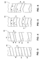
- Figure 3 is a planar, schematic illustration of an alternative groove alignment compared to the embodiment of Figure 1.
- Figure 4 schematically illustrates another alternative groove alignment.
- Figure 5 schematically illustrates another alternative groove alignment.
- Figure 6 schematically illustrates another alternative groove alignment.
- Figure 7 schematically illustrates a device and method useful for making a belt assembly designed according to an embodiment of this invention.
- Figures 1 and 2 schematically illustrate a belt assembly 20 that is designed for use in an elevator system.
- a plurality of cords 22 are aligned generally parallel to a longitudinal axis of the belt assembly 20.
- the cords 22 are made of strands of steel wire.
- a jacket 24 covers over the cords 22.
- the jacket 24 preferably comprises a polyurethane-based material.
- a variety of such materials are commercially available and known in the art to be useful for elevator belt assemblies. Given this description, those skilled in the art will be able to select a proper jacket material to suit the needs of their particular situation.
- the jacket 24 establishes an exterior length, L, width, W, and a thickness, t, of the belt assembly 20.
- the width W of the belt assembly is 30 millimeters
- the thickness t is 3 millimeters
- the depth of each groove is 0.7 millimeters.
- the cords 22 have a diameter of 1.65 millimeters.
- the cords 22 preferably extend along the entire length L of the assembly.
- the jacket 24 includes a plurality of grooves 30, 32, 34, 36, 38, 40 and 42 on at least one side of the jacket 24.
- the grooves extend across the entire width of the belt assembly.
- the noise component caused by contact of the belt assembly with other elevator system components, such as the sheaves, during system operation, is spread over a broader range of frequencies.
- steady state frequencies of noise are avoided which eliminates the potential for an audible, annoying tone.
- the segments are of various lengths, there is no periodic, repeated geometric pattern of the cords relative to the jacket outer surfaces.
- varying the length of the cord segments i.e., changing spacing between similar distortions in the position of the cord relative to the jacket outer surfaces
- any contribution to noise or vibration caused by the cord geometry is reduced or eliminated.
- this invention provides a significant advantage for reducing vibration and noise generation during elevator system operation.
- Figures 3 through 6 illustrate various strategies according to this invention for avoiding noise levels caused by belt movement during elevator operation.
- the example of Figure 3 includes a jacket 24a having a plurality of grooves 56.
- an equal spacing 58 separates adjacent grooves 56.
- the grooves 56 comprise straight lines extending across the width of the belt assembly.
- Each groove 56 is at an acute angle 60 relative to the longitudinal axis of the belt. Whether the angle of groove alignment is acute or obtuse depends only on a frame of reference.
- Arranging at least a portion of the grooves 56 to be non-perpendicular to the longitudinal axis of the belt avoids the steady state frequency of noise generation, that otherwise occurs when perpendicularly aligned grooves (and associated cord distortions) are equally spaced along the length of the belt.
- the example of Figure 6 includes a jacket 24d that has a plurality of grooves 70', each of which includes line segments 72' and 74'.
- different spacings 78 and 80 for example, separate each of the grooves from an adjacent groove.
- the machinery 100 includes a plurality of cord supports 110.
- the spacing between the cord supports is variable.
- the spacing between two adjacent cord supports 110 may be the same, it is preferred that the spacing between the cord supports 110 not be arranged in a repeating pattern.
- the spacing should be randomized within an acceptable range that will depend on the machinery.
Landscapes
- Engineering & Computer Science (AREA)
- General Engineering & Computer Science (AREA)
- Mechanical Engineering (AREA)
- Lift-Guide Devices, And Elevator Ropes And Cables (AREA)
- Cage And Drive Apparatuses For Elevators (AREA)
Description
- This invention generally relates to load bearing members for use in elevator systems. More particularly, this invention relates to an elevator belt assembly having a specialized groove arrangement.
- Elevator systems typically include a cab and counterweight that move within a hoistway to transport passengers or cargo to different landings within a building, for example. A load bearing member, such as roping or a belt typically moves over a set of sheaves and supports the load of the cab and counterweight. There are a variety of types of load bearing members used in elevator systems.
- One type of load bearing member is a coated steel belt. Typical arrangements include a plurality of steel cords extending along the length of the belt assembly. A jacket is applied over the cords and forms an exterior of the belt assembly. Some jacket application processes result in grooves being formed in the jacket surface on at least one side of the belt assembly. Some processes also tend to cause distortions or irregularities in the position of the steel cords relative to the exterior of the jacket along the length of the belt.
- Figure 8, for example, illustrates both of these phenomena. As can be seen, the spacing between the exterior of the
jacket 200 and thecords 210 varies along the length of the belt. As can be appreciated from the illustration, thecords 210 are set within the jacket as if they comprise a series of cord segments of equal length corresponding to the groove spacing. The illustration of Figure 8 includes an exaggeration of the typical physical cord layout for purposes of illustration. The actual distortions or changes in the position of the cords relative to the jacket outer surfaces may not be discernable by the human eye in some examples. - When conventional jacket application processes are used, the manner in which the cords are supported during the jacket application process tends to result in such distortion in the geometry or configuration of the cords relative to the jacket outer surfaces along the length of the belt.
- While such arrangements have proven useful, there is need for improvement. One particular difficulty associated with such belt assemblies is that as the belt moves in the elevator system, the grooves and the cord placement in the jacket interact with other system components such as the sheaves and generate undesirable noise, vibration or both. For example, as the belt assembly moves at a constant velocity, a steady state frequency of groove contact with the sheaves creates an annoying, audible tone. The repeated pattern of changes in the cord spacing from the jacket outer surfaces is believed to contribute to such noise generation.
- An alternative arrangement is required to minimize or eliminate the occurrence of vibrations or an annoying tone during elevator system operation. This invention addresses that need.
- In general terms, this invention is a belt assembly for use in an elevator system. The belt assembly includes a plurality of cords extending generally parallel to a longitudinal axis of the belt. A jacket over the cords includes a plurality of grooves that are situated to minimize the occurrence of an annoying audible tone during elevator operation.
- In one example, the grooves are longitudinally spaced such that spacings between the grooves varies along the length of the belt. Having different spacings between adjacent grooves eliminates the steady state frequency of groove contact with other system components, which is a major contributor to the potential for undesirable noise or vibration during elevator operation.
- In another example, the grooves extend across the width of the jacket. At least a portion of each of the grooves is aligned to be not perpendicular to the longitudinal axis of the belt. In one example, the grooves comprise straight lines. In another example, the grooves comprise a series of line segments, each of which is at a different angle relative to the longitudinal axis of the belt.
- A belt assembly designed according to this invention may include the inventive different spacings, the inventive angular alignment of the grooves or a combination of both. The various features and advantages of this invention will become apparent to those skilled in the art from the following detailed description of the currently preferred embodiments. The drawings that accompany the detailed description can be briefly described as follows.
- Figure I schematically illustrates a portion of an example belt assembly designed according to an embodiment of this invention.
- Figure 2 is a cross-sectional illustration taken along the lines 2-2 in Figure 1.
- Figure 3 is a planar, schematic illustration of an alternative groove alignment compared to the embodiment of Figure 1.
- Figure 4 schematically illustrates another alternative groove alignment.
- Figure 5 schematically illustrates another alternative groove alignment.
- Figure 6 schematically illustrates another alternative groove alignment.
- Figure 7 schematically illustrates a device and method useful for making a belt assembly designed according to an embodiment of this invention.
- Figure 8 schematically illustrates a typical cord geometry relative to outer surfaces on a belt jacket according to the prior art.
- Figures 1 and 2 schematically illustrate a
belt assembly 20 that is designed for use in an elevator system. A plurality ofcords 22 are aligned generally parallel to a longitudinal axis of thebelt assembly 20. In one example, thecords 22 are made of strands of steel wire. - A
jacket 24 covers over thecords 22. Thejacket 24 preferably comprises a polyurethane-based material. A variety of such materials are commercially available and known in the art to be useful for elevator belt assemblies. Given this description, those skilled in the art will be able to select a proper jacket material to suit the needs of their particular situation. - The
jacket 24 establishes an exterior length, L, width, W, and a thickness, t, of thebelt assembly 20. In one example, the width W of the belt assembly is 30 millimeters, the thickness t is 3 millimeters and the depth of each groove is 0.7 millimeters. In the same example, thecords 22 have a diameter of 1.65 millimeters. Thecords 22 preferably extend along the entire length L of the assembly. - The
jacket 24 includes a plurality ofgrooves jacket 24. In the illustrated example, the grooves extend across the entire width of the belt assembly. - The grooves result from some manufacturing processes, many of which are well known in the art, that are suitable for formation of the
belt assembly 20. In the example embodiment of Figures 1 and 2, the grooves are spaced apart different distances so that there are different spacings between various grooves. For example, afirst spacing 44 separates thegroove 30 from theadjacent groove 32. Adifferent spacing 46 separates thegroove 32 from theadjacent groove 34. Similarly, thespacings - It is not necessary that all of the illustrated spacings are different, however, it is preferred to provide as many different spacings along the length of the belt assembly as possible. As a practical matter, a repeated pattern of the varying spacings will typically extend along the entire length of the
belt assembly 20. Depending on the particulars of the belt assembly and the equipment used to form and apply thejacket 24, the pattern of different spacings will repeat at different intervals. Preferably, the interval of pattern repetition will be as large as the manufacturing equipment allows. In one example, there is a pattern of different spacings that repeats about every two meters. Within each two meter section, the spacings between adjacent grooves are selected to be varying and non-periodic. - By altering spacings between adjacent grooves, the noise component, caused by contact of the belt assembly with other elevator system components, such as the sheaves, during system operation, is spread over a broader range of frequencies. Thus, steady state frequencies of noise are avoided which eliminates the potential for an audible, annoying tone.
- In addition to varying the spacing between the grooves, the inventive arrangement provides the ability to vary the lengths of cord "segments," which result from certain manufacturing techniques (but are not necessarily included in the inventive arrangement). A belt assembly designed according to this invention may include a series of cord segments along which the distance between the cord and the jacket outer surfaces varies. The ends of such cord "segments" coincide with the location of the grooves. Varying the spacing of the grooves also varies the length of the segments and therefore varies the pattern of the cord geometry relative to the jacket outer surfaces. With the inventive arrangement, the length of the cord segments varies along the length of the belt.
- Because the segments are of various lengths, there is no periodic, repeated geometric pattern of the cords relative to the jacket outer surfaces. By varying the length of the cord segments (i.e., changing spacing between similar distortions in the position of the cord relative to the jacket outer surfaces) any contribution to noise or vibration caused by the cord geometry, is reduced or eliminated.
- By eliminating the periodic feature of the cord geometry, this invention provides a significant advantage for reducing vibration and noise generation during elevator system operation.
- Figures 3 through 6 illustrate various strategies according to this invention for avoiding noise levels caused by belt movement during elevator operation. The example of Figure 3 includes a
jacket 24a having a plurality ofgrooves 56. In this example, anequal spacing 58 separatesadjacent grooves 56. Thegrooves 56 comprise straight lines extending across the width of the belt assembly. Eachgroove 56 is at anacute angle 60 relative to the longitudinal axis of the belt. Whether the angle of groove alignment is acute or obtuse depends only on a frame of reference. Arranging at least a portion of thegrooves 56 to be non-perpendicular to the longitudinal axis of the belt avoids the steady state frequency of noise generation, that otherwise occurs when perpendicularly aligned grooves (and associated cord distortions) are equally spaced along the length of the belt. - The example of Figure 4 includes a
jacket 24b having a plurality ofgrooves 56'. Thegrooves 56' are spaced apart usingdifferent spacings grooves 56' are aligned at anacute angle 60 relative to the longitudinal axis of the belt. The example of Figure 4 combines the inventive angular alignment of the grooves with the inventive varying spacing strategy, either or both of which can be employed in the present invention. - Figure 5 illustrates another example belt assembly having a
jacket 24c. In this example, a plurality ofgrooves 70 each have a plurality ofline segments grooves 70 are equally spaced using aspacing 76. Because theline segments grooves 70 were straight lines that were perpendicular to the longitudinal axis of the belt. - The example of Figure 6 includes a
jacket 24d that has a plurality of grooves 70', each of which includes line segments 72' and 74'. In this example,different spacings - With reference to Figure 7, the process of making an elevator belt assembly designed according to this invention is schematically illustrated by
machinery 100. Thecords 22 move through themachinery 100 which provides a mold for forming thejacket 24. - The
machinery 100 includes a plurality of cord supports 110. In the case of forming the belt assemblies of Figures 1, 4 and 6, the spacing between the cord supports is variable. Although the spacing between two adjacent cord supports 110 may be the same, it is preferred that the spacing between the cord supports 110 not be arranged in a repeating pattern. Preferably, the spacing should be randomized within an acceptable range that will depend on the machinery. - As the
cords 22 are fed through themachinery 100 they are supported on each of the cord supports. In examples where thecords 22 are fed continuously, the cord supports 110 move as thecords 22 are fed through themachinery 100. A polyurethane-based jacket material is fed into the machinery from a reservoir 122 in a conventional manner. As the jacket material envelopes thecords 22, the cord supports cause grooves to be formed in the jacket. The machinery preferably causes an opposite side of thejacket 24 to be flat. Themachinery 100 operates in a known manner to extrude, mold or otherwise form thejacket 24 around thecords 22. - Providing different spacing between the cord supports yields different spacing between the grooves along the length of the belt.
- In another example, as in forming the belt assemblies of Figures 3-6, the cord supports have a configuration that provides a desired groove alignment on the exterior surface of the
jacket 24. Example groove configurations and alignments are shown in Figures 3-6, but this invention is not limited to those examples. - By placing the grooves in a desired alignment, the difficulties of audible noise generation experienced with conventional coated belt assemblies can be at least greatly reduced and usually eliminated. Providing different spacings between grooves or a properly selected angular alignment of at least a part of each groove, or a combination of both results in a much quieter arrangement.
- The preceding description is exemplary rather than limiting in nature. Variations and modifications to the disclosed examples may become apparent to those skilled in the art that do not necessarily depart from the essence of this invention. The scope of legal protection given to this invention can only be determined by studying the following claims.
Claims (16)
- An elevator belt assembly (20), comprising:a plurality of cords (22) aligned generally parallel to a longitudinal axis of the belt; anda jacket (24) over the cords, the jacket including a plurality of grooves (30-42) that are spaced longitudinally on at least one side of the jacket that spacings (44-54) between , characterised in, adjacent grooves vary along a length of the belt assembly.
- The assembly (20) of claim 1, wherein three sequential ones of the spacings (44, 46, 48) between the grooves (30, 32, 34) are all different from one another.
- The assembly of claim 1 or 2, wherein the grooves (56, 70) extend across the width of the jacket (24) and wherein at least a portion of each of the grooves is aligned not perpendicular to the longitudinal axis of the belt.
- The assembly (20) of claim 1 or 2, wherein the grooves (30-42) extend across the width of the jacket (24) and wherein the grooves are aligned generally perpendicular to the longtudinal axis of the belt.
- The assembly of claim 1, 2 or 3, wherein each groove (70) comprises a plurality of line segments (72, 74) and at least one of the segments is at a non-right angle relative to the longitudinal axis of the belt.
- The assembly of claim 3, wherein the grooves extend across the width of the jacket and wherein each groove comprises a plurality of line segments, wherein at least one of the segments is at an acute angle relative to the longitudinal axis of the belt.
- The assembly of claim 6, wherein each line segment (72, 74) of a particular one of the grooves (70) is at a different angle relative to the longitudinal axis.
- The assembly of claim 3, wherein the grooves (56) extend across the width of the jacket (24) and wherein each groove comprises a generally straight line.
- The assembly of any preceding claim, wherein the cords (22) comprise steel wires and the jacket (24) comprises as elastomer.
- The assembly of claim 9, wherein the elastomer comprises polyurethane.
- A method of making an elevator belt assembly having a plurality of cords (22) within a jacket (24), comprising the steps of:(a) aligning the plurality of cords in a selected arrangement; and(b) applying the jacket to the cords while supporting the cords using cord supports (110) that cause the applied jacket to include a plurality of longitudinally spaced grooves (56'; 70') that are formed in the jacket, where the cord supports are oriented such that the grooves are disposed at least in part at a non-right angle to the longitudinal axis, and spaced at varying longitudinal intervals.
- The method of claim 11 including spacing the grooves (56') such that three sequential spacings (62, 64, 66) between the grooves (56') are all different from each other.
- The method of claim 11 or 12 wherein at least a portion of each of the grooves (56'; 70') is aligned at an acute angle to the longitudinal axis of the belt.
- An elevator belt, comprising:a plurality of cords (22) aligned generally parallel to a longitudinal axis of the belt; anda jacket (24) over the cords and having a plurality of longitudinally spaced grooves (56'; 70') that penetrate a side of the jacket, characterised in that, the grooves beingdisposed in part at a non-right angle to the longitudinal axis, andspaced at varying longitudinal intervals.
- The elevator belt (20) of claim 14, wherein three sequential ones of the longitudinal intervals (62, 64, 66) are all different from each other.
- The elevator belt of claim 14 or 15, wherein a first portion (72) of each groove is disposed at a first non-right angle to the longitudinal axis and a second portion (74) of each groove is disposed at a second non-right angle to the longitudinal axis.
Applications Claiming Priority (3)
| Application Number | Priority Date | Filing Date | Title |
|---|---|---|---|
| US970587 | 2001-10-04 | ||
| US09/970,587 US7670240B2 (en) | 2001-10-04 | 2001-10-04 | Elevator belt assembly with noise reducing groove arrangement |
| PCT/US2002/029817 WO2003029556A1 (en) | 2001-10-04 | 2002-09-19 | Elevator belt assembly with noise reducing groove arrangement |
Publications (2)
| Publication Number | Publication Date |
|---|---|
| EP1434914A1 EP1434914A1 (en) | 2004-07-07 |
| EP1434914B1 true EP1434914B1 (en) | 2006-04-12 |
Family
ID=25517168
Family Applications (1)
| Application Number | Title | Priority Date | Filing Date |
|---|---|---|---|
| EP02761752A Expired - Lifetime EP1434914B1 (en) | 2001-10-04 | 2002-09-19 | Elevator belt assembly with noise reducing groove arrangement |
Country Status (8)
| Country | Link |
|---|---|
| US (1) | US7670240B2 (en) |
| EP (1) | EP1434914B1 (en) |
| JP (2) | JP4246063B2 (en) |
| KR (1) | KR100871276B1 (en) |
| CN (1) | CN100352998C (en) |
| DE (1) | DE60210644T2 (en) |
| ES (1) | ES2259095T3 (en) |
| WO (1) | WO2003029556A1 (en) |
Families Citing this family (20)
| Publication number | Priority date | Publication date | Assignee | Title |
|---|---|---|---|---|
| WO2003062117A1 (en) * | 2002-01-16 | 2003-07-31 | Otis Elevator Company | Elevator system design including a belt assembly with a vibration and noise reducing groove configuration |
| US7971687B2 (en) * | 2003-02-07 | 2011-07-05 | Otis Elevator Company | Elevator belt assembly with noise reducing groove arrangement |
| ES2350447T3 (en) * | 2003-12-22 | 2011-01-24 | Otis Elevator Company | ASSEMBLY TRACTION ELEMENTS ASSEMBLY TECHNIQUES. |
| DK1555234T3 (en) * | 2004-01-06 | 2006-08-21 | Inventio Ag | Elevator |
| ES2353504T5 (en) | 2004-03-15 | 2018-04-30 | Otis Elevator Company | Method of manufacturing an elevator load bearing member having a wrap with at least one rough outer surface |
| ES2402930T5 (en) * | 2005-09-13 | 2016-12-05 | Otis Elevator Company | Method of manufacturing a load bearing element for an elevator system |
| BRPI0721977A2 (en) * | 2007-09-27 | 2014-03-18 | Otis Elevator Company | LOAD SUPPORT MEMBER TO SUPPORT A LIFT CAR, AND, LIFT |
| ATE523461T1 (en) * | 2008-09-30 | 2011-09-15 | Kone Corp | ELEVATOR |
| BRPI0922055A2 (en) * | 2008-11-19 | 2015-12-22 | Inventio Ag | elevator installation support belt. |
| EP2210847A1 (en) * | 2009-01-22 | 2010-07-28 | Inventio AG | Lift facility with drive disc |
| JP5688450B2 (en) * | 2010-05-13 | 2015-03-25 | オーチス エレベータ カンパニーOtis Elevator Company | Method for producing a fabric having a desired separation distance between tension members |
| WO2011151401A1 (en) * | 2010-06-04 | 2011-12-08 | Knauf Gips Kg | Transporting belt |
| JP6225737B2 (en) * | 2014-02-13 | 2017-11-08 | Nok株式会社 | Industrial belt |
| EP2990370B1 (en) * | 2014-09-01 | 2017-06-14 | KONE Corporation | Elevator |
| KR102453328B1 (en) * | 2015-12-08 | 2022-10-12 | 주식회사 만도 | Electric Power Steering Apparatus |
| US10556775B2 (en) | 2016-02-09 | 2020-02-11 | Otis Elevator Company | Surface construction of elevator belt |
| JP6533258B2 (en) * | 2017-08-15 | 2019-06-19 | ジャン ミンジョンJANG, Min Jeong | Elevator balance rope {Balancing Rope for Elevator} |
| CN109399421A (en) * | 2017-08-17 | 2019-03-01 | 张旻贞 | Balance rope for elevator |
| KR101984733B1 (en) * | 2017-12-18 | 2019-06-21 | (주) 코엘코 | Balancing lope |
| US10926976B2 (en) * | 2018-06-18 | 2021-02-23 | Otis Elevator Company | Belt with corrugated material |
Family Cites Families (20)
| Publication number | Priority date | Publication date | Assignee | Title |
|---|---|---|---|---|
| JPS4815497B1 (en) * | 1968-03-04 | 1973-05-15 | ||
| US4011766A (en) * | 1976-02-19 | 1977-03-15 | Dayco Corporation | Endless power transmission belt |
| JPS5724997Y2 (en) * | 1978-10-30 | 1982-05-31 | ||
| DE2906619C2 (en) * | 1979-02-21 | 1981-05-21 | Bayerische Motoren Werke AG, 8000 München | Timing belt |
| FR2483660A1 (en) | 1980-05-30 | 1981-12-04 | Klaxon Sa | IMPROVEMENTS ON PNEUMATIC AUDITORS |
| US4486375A (en) * | 1983-02-23 | 1984-12-04 | Mitsuboshi Belting Ltd. | Method of manufacturing toothed belts |
| US4534437A (en) * | 1983-09-09 | 1985-08-13 | Dayco Corporation | Snow track belt for motorcycle |
| US4605389A (en) * | 1985-04-22 | 1986-08-12 | The Gates Rubber Company | Toothed belt and sprocket |
| US4976662A (en) * | 1988-02-05 | 1990-12-11 | Dayco Products, Inc. | Endless power transmission belt construction and method of making the same |
| US5055090A (en) | 1988-02-05 | 1991-10-08 | Dayco Products, Inc. | Endless power transmission belt construction and method of making the same |
| DE68911794T2 (en) * | 1988-08-12 | 1994-07-07 | Bando Chemical Ind | Belt gear and pulley. |
| JP2969463B2 (en) * | 1989-05-22 | 1999-11-02 | デイコ プロダクツ,インコーポレイテッド | Endless transmission belt |
| DE4016469A1 (en) | 1990-05-22 | 1991-11-28 | Continental Ag | V-belt for power transmission - has oblique transverse grooves of irregular pitch cut in its inner surface |
| US5211608A (en) | 1991-06-27 | 1993-05-18 | Xerox Corporation | Low noise timing belt |
| US5308291A (en) * | 1992-10-16 | 1994-05-03 | Dayco Products, Inc. | Belt construction, the combination of the belt construction and a pulley and methods of making the same |
| US5382198A (en) | 1994-01-26 | 1995-01-17 | The Goodyear Tire & Rubber Company | Helically grooved multi-ribbed power transmission belt |
| JP2853730B2 (en) * | 1995-03-08 | 1999-02-03 | 日本メクトロン株式会社 | Flat belt |
| WO1998029327A1 (en) * | 1996-12-30 | 1998-07-09 | Kone Corporation | Elevator rope arrangement |
| ES2262368T5 (en) | 1998-12-22 | 2011-10-28 | Otis Elevator Company | TENSION ELEMENT FOR AN ELEVATOR. |
| US6484368B1 (en) * | 2000-01-11 | 2002-11-26 | Otis Elevator Company | Flexible flat tension member termination device |
-
2001
- 2001-10-04 US US09/970,587 patent/US7670240B2/en not_active Expired - Lifetime
-
2002
- 2002-09-19 JP JP2003532757A patent/JP4246063B2/en not_active Expired - Fee Related
- 2002-09-19 KR KR1020047004007A patent/KR100871276B1/en not_active Expired - Fee Related
- 2002-09-19 EP EP02761752A patent/EP1434914B1/en not_active Expired - Lifetime
- 2002-09-19 CN CNB028197453A patent/CN100352998C/en not_active Expired - Lifetime
- 2002-09-19 DE DE60210644T patent/DE60210644T2/en not_active Expired - Lifetime
- 2002-09-19 WO PCT/US2002/029817 patent/WO2003029556A1/en not_active Ceased
- 2002-09-19 ES ES02761752T patent/ES2259095T3/en not_active Expired - Lifetime
-
2008
- 2008-11-10 JP JP2008287275A patent/JP5068729B2/en not_active Expired - Fee Related
Also Published As
| Publication number | Publication date |
|---|---|
| ES2259095T3 (en) | 2006-09-16 |
| US20030069101A1 (en) | 2003-04-10 |
| DE60210644T2 (en) | 2006-08-24 |
| JP2009029635A (en) | 2009-02-12 |
| DE60210644D1 (en) | 2006-05-24 |
| KR20040048894A (en) | 2004-06-10 |
| US7670240B2 (en) | 2010-03-02 |
| CN1564899A (en) | 2005-01-12 |
| CN100352998C (en) | 2007-12-05 |
| JP5068729B2 (en) | 2012-11-07 |
| EP1434914A1 (en) | 2004-07-07 |
| KR100871276B1 (en) | 2008-11-28 |
| JP4246063B2 (en) | 2009-04-02 |
| JP2005504691A (en) | 2005-02-17 |
| WO2003029556A1 (en) | 2003-04-10 |
Similar Documents
| Publication | Publication Date | Title |
|---|---|---|
| US7670240B2 (en) | Elevator belt assembly with noise reducing groove arrangement | |
| EP1599406B1 (en) | Elevator belt assembly with noise reducing groove arrangement | |
| KR101229031B1 (en) | An elevator load bearing member | |
| KR100836452B1 (en) | Methods of manufacturing and installing sets of flat tension members, elevator systems, and multiple flat tension members for elevator systems | |
| US8444515B2 (en) | Elevator belt assembly with noise and vibration reducing grooveless jacket arrangement | |
| US20130292211A1 (en) | System And Method For Reducing Belt Noise | |
| US7748501B2 (en) | Elevator system design including a belt assembly with a vibration and noise reducing groove configuration | |
| HK1091188B (en) | An elevator belt and an elevator system using the belt | |
| HK1076089B (en) | Elevator system design including a belt assembly with a vibi ation and noise reducing groove configuration | |
| HK1121727B (en) | An elevator belt assembly for an elevator system |
Legal Events
| Date | Code | Title | Description |
|---|---|---|---|
| PUAI | Public reference made under article 153(3) epc to a published international application that has entered the european phase |
Free format text: ORIGINAL CODE: 0009012 |
|
| 17P | Request for examination filed |
Effective date: 20040430 |
|
| AK | Designated contracting states |
Kind code of ref document: A1 Designated state(s): AT BE BG CH CY CZ DE DK EE ES FI FR GB GR IE IT LI LU MC NL PT SE SK TR |
|
| GRAP | Despatch of communication of intention to grant a patent |
Free format text: ORIGINAL CODE: EPIDOSNIGR1 |
|
| GRAS | Grant fee paid |
Free format text: ORIGINAL CODE: EPIDOSNIGR3 |
|
| GRAA | (expected) grant |
Free format text: ORIGINAL CODE: 0009210 |
|
| AK | Designated contracting states |
Kind code of ref document: B1 Designated state(s): DE ES FR GB IT |
|
| REG | Reference to a national code |
Ref country code: GB Ref legal event code: FG4D |
|
| REF | Corresponds to: |
Ref document number: 60210644 Country of ref document: DE Date of ref document: 20060524 Kind code of ref document: P |
|
| REG | Reference to a national code |
Ref country code: ES Ref legal event code: FG2A Ref document number: 2259095 Country of ref document: ES Kind code of ref document: T3 |
|
| ET | Fr: translation filed | ||
| PLBE | No opposition filed within time limit |
Free format text: ORIGINAL CODE: 0009261 |
|
| STAA | Information on the status of an ep patent application or granted ep patent |
Free format text: STATUS: NO OPPOSITION FILED WITHIN TIME LIMIT |
|
| 26N | No opposition filed |
Effective date: 20070115 |
|
| PGFP | Annual fee paid to national office [announced via postgrant information from national office to epo] |
Ref country code: GB Payment date: 20140917 Year of fee payment: 13 |
|
| PGFP | Annual fee paid to national office [announced via postgrant information from national office to epo] |
Ref country code: IT Payment date: 20140918 Year of fee payment: 13 |
|
| PG25 | Lapsed in a contracting state [announced via postgrant information from national office to epo] |
Ref country code: IT Free format text: LAPSE BECAUSE OF NON-PAYMENT OF DUE FEES Effective date: 20150919 |
|
| GBPC | Gb: european patent ceased through non-payment of renewal fee |
Effective date: 20150919 |
|
| PG25 | Lapsed in a contracting state [announced via postgrant information from national office to epo] |
Ref country code: GB Free format text: LAPSE BECAUSE OF NON-PAYMENT OF DUE FEES Effective date: 20150919 |
|
| REG | Reference to a national code |
Ref country code: FR Ref legal event code: PLFP Year of fee payment: 15 |
|
| REG | Reference to a national code |
Ref country code: DE Ref legal event code: R082 Ref document number: 60210644 Country of ref document: DE Representative=s name: SCHMITT-NILSON SCHRAUD WAIBEL WOHLFROM PATENTA, DE |
|
| REG | Reference to a national code |
Ref country code: FR Ref legal event code: PLFP Year of fee payment: 16 |
|
| REG | Reference to a national code |
Ref country code: FR Ref legal event code: PLFP Year of fee payment: 17 |
|
| PGFP | Annual fee paid to national office [announced via postgrant information from national office to epo] |
Ref country code: FR Payment date: 20210819 Year of fee payment: 20 |
|
| PGFP | Annual fee paid to national office [announced via postgrant information from national office to epo] |
Ref country code: DE Payment date: 20210818 Year of fee payment: 20 |
|
| PGFP | Annual fee paid to national office [announced via postgrant information from national office to epo] |
Ref country code: ES Payment date: 20211001 Year of fee payment: 20 |
|
| REG | Reference to a national code |
Ref country code: DE Ref legal event code: R071 Ref document number: 60210644 Country of ref document: DE |
|
| REG | Reference to a national code |
Ref country code: ES Ref legal event code: FD2A Effective date: 20220926 |
|
| PG25 | Lapsed in a contracting state [announced via postgrant information from national office to epo] |
Ref country code: ES Free format text: LAPSE BECAUSE OF EXPIRATION OF PROTECTION Effective date: 20220920 |