EP1434467B1 - Commercial microwave oven, and more particularly to a commercial oven which can dissipate heat from components - Google Patents
Commercial microwave oven, and more particularly to a commercial oven which can dissipate heat from components Download PDFInfo
- Publication number
- EP1434467B1 EP1434467B1 EP03025608A EP03025608A EP1434467B1 EP 1434467 B1 EP1434467 B1 EP 1434467B1 EP 03025608 A EP03025608 A EP 03025608A EP 03025608 A EP03025608 A EP 03025608A EP 1434467 B1 EP1434467 B1 EP 1434467B1
- Authority
- EP
- European Patent Office
- Prior art keywords
- microwave oven
- inner case
- magnetron
- commercial microwave
- fan
- Prior art date
- Legal status (The legal status is an assumption and is not a legal conclusion. Google has not performed a legal analysis and makes no representation as to the accuracy of the status listed.)
- Expired - Lifetime
Links
- 238000010411 cooking Methods 0.000 claims description 13
- 230000001105 regulatory effect Effects 0.000 claims description 4
- 238000004519 manufacturing process Methods 0.000 description 4
- 230000017525 heat dissipation Effects 0.000 description 3
- 238000007664 blowing Methods 0.000 description 2
- 238000001816 cooling Methods 0.000 description 2
- 230000005540 biological transmission Effects 0.000 description 1
- 230000001419 dependent effect Effects 0.000 description 1
- 238000013021 overheating Methods 0.000 description 1
- 230000003252 repetitive effect Effects 0.000 description 1
Images


Classifications
-
- F—MECHANICAL ENGINEERING; LIGHTING; HEATING; WEAPONS; BLASTING
- F24—HEATING; RANGES; VENTILATING
- F24C—DOMESTIC STOVES OR RANGES ; DETAILS OF DOMESTIC STOVES OR RANGES, OF GENERAL APPLICATION
- F24C7/00—Stoves or ranges heated by electric energy
- F24C7/02—Stoves or ranges heated by electric energy using microwaves
-
- H—ELECTRICITY
- H05—ELECTRIC TECHNIQUES NOT OTHERWISE PROVIDED FOR
- H05B—ELECTRIC HEATING; ELECTRIC LIGHT SOURCES NOT OTHERWISE PROVIDED FOR; CIRCUIT ARRANGEMENTS FOR ELECTRIC LIGHT SOURCES, IN GENERAL
- H05B6/00—Heating by electric, magnetic or electromagnetic fields
- H05B6/64—Heating using microwaves
- H05B6/642—Cooling of the microwave components and related air circulation systems
-
- H—ELECTRICITY
- H05—ELECTRIC TECHNIQUES NOT OTHERWISE PROVIDED FOR
- H05B—ELECTRIC HEATING; ELECTRIC LIGHT SOURCES NOT OTHERWISE PROVIDED FOR; CIRCUIT ARRANGEMENTS FOR ELECTRIC LIGHT SOURCES, IN GENERAL
- H05B2206/00—Aspects relating to heating by electric, magnetic, or electromagnetic fields covered by group H05B6/00
- H05B2206/04—Heating using microwaves
- H05B2206/044—Microwave heating devices provided with two or more magnetrons or microwave sources of other kind
Definitions
- the present invention relates to microwave ovens, and more particularly, to a commercial microwave oven which can dissipate heat from components, effectively.
- the microwave oven cooks food with heat from friction between molecules caused by disturbance of the molecular arrangement of the food made with a microwave (approx. 2,450MHz).
- the microwave oven may have one or a plurality of magnetrons.
- Microwave oven with one magnetron is employed as domestic use where the microwave oven is not used frequently, and microwave oven with a plurality of magnetrons is employed as commercial use for convenience store and the like where high power is required continuously.
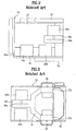
- FIGS. 1 ⁇ 3 illustrate inside structures of related art commercial microwave ovens, schematically.
- the related art commercial microwave oven is provided with an outer case 11, a base plate 12, an inner case 13, a front panel 14, a rear panel 15, one pair of magnetrons, transformers, and an outfit chamber.
- An inside space of the inner case is a cooking chamber.
- the outfit chamber is one side space of an inside space of the microwave oven excluding a part occupied by the inner case, where different components are provided.
- the magnetrons 17a and 17b and the transformers 16a and 16b generate much heat. Particularly, when the microwave oven is used in a convenience store or the like, it is liable that the magnetrons 17a and 17b are overheated and damaged due to continued use. Therefore, a structure that can cool down the magnetrons 17a and 17b and the transformers 16a and 16b adequately is required.
- the base plate 12 has a plurality of inlet holes 12a in a front surface for drawing external air, and the rear panel 15 has outlet holes 15a for exhaust of air.
- FIGS. 2 and 3 illustrate a side view and a rear view of the related art microwave oven, respectively.
- the one pair of transformers 16a and 16b are mounted on one side of the outfit chamber, and the magnetrons 17a and 17b are mounted on a top and a bottom of a rear part of the inner case 13.
- the location of the one pair of the magnetrons 17a and 17b far from each other requires a complicated air supply structure for the fan 18a to blow the external air thereto.
- a duct 19 is provided for making an air outlet of the fan and the magnetrons 17a and 17b are in communication.
- a centrifugal fan is employed as the fan for drawing external air and blowing the air in a direction perpendicular to an air draw direction.
- the external air passes through the fan 18a, flows along the duct 19, and cools the magnetrons 17a and 17b. Then, the air exhausts through the outlet holes 15a in the rear panel 15.
- the occupation of a rear space by the plurality of magnetrons and the duct causes a volume of a rear part of the microwave oven large.
- a microwave oven with a main cabinet for enclosing and protecting various components which is provided with air inlet holes.
- the microwave oven has an U-shaped box-like base frame under the main cabinet with an open top and air outlet holes formed in side parts.
- On the base frame is arranged a bottom plate supporting a transformer for providing a voltage to a magnetron which is positioned at an upper part at a side of an inner case defining a cooking chamber.
- the magnetron is connected to the side wall of the inner case via a wave gate.
- a fan is arranged in an area of a space outside of the inner case and is directed to blow air towards the magnetron. The air blown by the fan is distributed within the space at the side of the inner case and is exhausted to the outside of the microwave oven via holes formed in the bottom plate and the air outlet holes at the sides of the base frame.
- the present invention is directed to a commercial microwave oven that substantially obviates one or more of the problems due to limitations and disadvantages of the related art.
- An object of the present invention is to provide a commercial microwave oven which has a reduced overall volume while a size of a cooking chamber is kept the same.
- Another aspect of the present invention is to provide a commercial microwave oven which can reduce a production cost.
- the present invention provides a commercial microwave oven as defined in claim 1, claim 3 or claim 5.
- Preferred embodiments are defined in the dependent claims.
- the bottom plate has an opening adjacent to the air outlet holes.
- the flow guide is provided between the magnetron and the air outlet holes.
- the flow guide is formed of a thin plate having a lower part the more bent forward with a slope as it goes down the farther.
- the main cabinet includes an outer case forming a top and sides of the microwave oven, a front panel on a front part of the outer case, and a rear panel on a rear part of the outer case having air inlets.
- the waveguide has one end in communication with a bottom of the inner case, and the other end in communication with the magnetron.
- the commercial microwave oven further includes a supporting frame having a bottom part fixed to the base frame, and a top part the transformer is mounted thereon.
- the fan has a central part mounted at a height in the middle of a height of the magnetron and a height of the transformer.
- the inner case For introduction of air into the cooking chamber, the inner case has inlet holes in a side surface adjacent to the magnetron.
- the fan is an axial fan.
- the first waveguide has one end in communication with a bottom of the inner case, and the other end in communication with the first magnetron, and the second waveguide has one end in communication with a top of the inner case, and the other end in communication with the second magnetron.
- the transformer is provided as one pair so as to be connected to respective magnetrons in side by side opposite to the fan for effective heat dissipation.
- the commercial microwave oven of the present invention employs single magnetron. That is, as performance of the magnetron is improved, application of a single magnetron even to the commercial microwave oven is made possible. According to this, the present invention suggests an effective ventilating system for preventing overheating of the single magnetron caused by continued operation thereof.
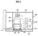
- Embodiments of the ventilating system of the commercial microwave oven of the present invention will be described with reference to FIGS. 4 to 7 .
- the first embodiment commercial microwave oven includes a main cabinet 100, a base frame 110, a bottom plate 131, an inner case 130, a magnetron 141, a transformer 142, a waveguide 160, a fan 171, and a flow guide 190.
- the main cabinet 100 forms an outer shape of the microwave oven, and encloses and protects various components.
- the main cabinet 100 has an outer case 101, a front panel 120, and a rear panel 180.
- the outer case 101 forms a top and sides of the microwave oven.
- the front panel 120 is mounted on a front part of the outer case 101, and the rear panel 180 is mounted to a rear part of the outer case 101. There are door and the like in front of the front panel 120.
- the base frame 110 forms a bottom of the microwave oven, and has a box form with an opened top and a front part with a plurality of air outlet holes 111.
- the bottom plate 131 is mounted on the base frame 110, on a side part of which the inner case 130 is mounted.
- the bottom plate 131 has an opening 131a in the vicinity of the air outlet holes 111.
- the opening 131a leads the air from the fan 171 to the air outlet holes 111.
- the inner case 130 forms a cooking chamber therein, and outer case of which is used as an outfit chamber for different components. That is, a space in the main cabinet 100, excluding the space of the inner case 130, is the outfit chamber. Also, there are inlet holes 132 in one side of the inner case 130 for making the cooking chamber and the outfit chamber in communication.
- the magnetron 141 and the transformer 142 are mounted on a side of the inner case 130 on a central part of the bottom plate 131 extended to the outfit chamber.
- the magnetron 141 is mounted on the bottom plate 131, and an opening is made in the bottom plate 131 under a part of the magnetron having a microwave generating part located thereon.
- the transformer 142 is positioned in a space over the magnetron 141, fixed on a supporting frame 150 over the magnetron 141.
- the supporting frame 150 is mounted on the base frame 110 so as to be projected upward, and divide mounting spaces of the transformer 142 and the magnetron 141. Also, as shown, it is preferable that the supporting frame 150 is mounted such that the air flow is not interfered.
- the waveguide 160 is mounted in a space between the bottom plate 131 and the base frame 110 along a bottom of the bottom plate 131.
- the waveguide 160 has one end in communication with an inside of the inner case 130, and the other end in communication with the microwave generating part of the magnetron 141 at the opened part 131b of the bottom plate 131.
- the waveguide 160 transmits the microwave from the magnetron 141 to the cooking chamber in the inner case 130.
- the fan 171 is mounted on the bottom part 131 in rear of the outfit chamber, for blowing air toward the space in which the magnetron 141 and the transformer 142 are provided.
- the rear panel 180 has air inlets 181 adjacent to the fan 171 for drawing air when the fan 171 is driven.
- a central part of the fan 171 is positioned at a height of the supporting frame 150 substantially, for uniform flow of the blown air to the magnetron 141 and the transformer 142.
- the fan 117 is of an axial type.
- the flow guide 190 between the magnetron 141 and the air outlet holes 111 guides air flow, and divides an inside space of the outfit chamber.
- the flow guide 190 has a lower part the more bent forward with a slope as it goes down the farther for guiding the air passed through the magnetron 141 and the transformer 142 toward the air outlet holes 111 in a front part of the base frame 110.
- the fan motor 172 Upon putting the microwave oven into operation, the fan motor 172 is driven, to rotate the fan 171. As the fan 171 rotates, external air is drawn through the air inlets 181 in the rear panel 180. The air passes through the fan 171 and cools down the magnetron 141 and the transformer 142 in front of the fan 171.
- the air flow is divided into an upper part flow and a lower part flow with reference to the supporting frame 150.
- the upper part flow flowing through an upper part of the supporting frame 150 cools down the transformer 142, and a portion of which is introduced into the cooking chamber through the inlet holes 132 in one side of the inner case 130.
- the other portion of the air, passed through the transformer 142 is guided by the flow guide 190 toward a lower space and joins with the lower part flow having flowed through a space under the supporting frame and cooled the magnetron 141.
- the air joined thus is guided by the flow guide 190 toward, and passes through the opening 131a in a front part of the bottom plate 131, and exhausts to an outside of the microwave oven through the air outlet holes 111 in the front part of the base frame 110.
- the commercial microwave oven of the present invention can not but have a system in which the microwave is provided to the cooking chamber through the bottom of the inner case 130, not necessarily.
- a commercial microwave oven in accordance with a second preferred embodiment of the present invention has a waveguide 161 mounted on a top surface of the inner case 130.
- a magnetron is mounted on an upper part of outside surface of the inner case.
- a microwave generating part of the magnetron 141 is in communication with one end of the waveguide 161 on the top surface of the inner case 130.
- a transformer 142 is provided in the outfit chamber. The transformer 142 mounted on a supporting frame 150 and positioned in a space over bottom plate 131. According to this, a center of a fan 171 is positioned at a height in the middle of the heights of the magnetron 141 and the transformer 142.
- a commercial microwave oven in accordance with a third preferred embodiment of the present invention has two magnetrons provided to an upper part and a lower part of the outfit chamber on a side of the inner case.
- the commercial microwave oven in accordance with a third preferred embodiment of the present invention has one pair of magnetrons 141a and 141b. That is, two magnetrons are provided to an upper part and a lower part of the outfit chamber on a side of the inner case, for providing the microwaves through a top surface and a bottom surface of the inner case 130.
- a first waveguide 161 is mounted on the top surface of the inner case 130
- a second waveguide 160 is mounted on an underside of the bottom plate 131 extended from the outfit chamber to the bottom of the inner case 130.
- the first magnetron 141a is mounted in an upper part of an outside of the inner case 130
- the second magnetron 141b is mounted in a lower part of outside of the inner case 130.
- One end of the first waveguide 161 is in communication with the first magnetron 141a
- the second waveguide 160 is in communication with the second magnetron 141b. Accordingly, the waves generated from the magnetrons are provided to the top and bottom of the inner case 130 at the same time, thereby increasing an output and providing microwaves from top and bottom uniformly.
- one pair of transformers 142a and 142b are provided, and the transformers are mounted on top of the supporting frame 150.
- the transformers 142a and 142b and the magnetrons 141a and 141b are cooled down by external air blown from the fan 171 in rear of the outfit chamber. As shown in FIG. 8 , for better cooling of the transformers 142a and 142b, it is preferable that the transformers 141a and 142b are mounted side by side at a position opposite to the fan 171.
- a position of microwave transmission to the cooking chamber and a number of the magnetrons may be varied, as well as an effective air flow system can be provided, thereby permitting to cope with different product requirements.
- systems of the main cabinet, the inner case and the like in the second or third embodiments are the same with the first embodiment.
- the commercial microwave oven of the present invention has the following advantages.
- the simplified ventilating system reduces an overall volume of the microwave oven, thereby permitting to install the microwave oven even in a small space.
- the flow guide permits to provide an effective heat dissipation system.
Description
- The present invention relates to microwave ovens, and more particularly, to a commercial microwave oven which can dissipate heat from components, effectively.
- In general, the microwave oven (MWO) cooks food with heat from friction between molecules caused by disturbance of the molecular arrangement of the food made with a microwave (approx. 2,450MHz). The microwave oven may have one or a plurality of magnetrons.
- Microwave oven with one magnetron is employed as domestic use where the microwave oven is not used frequently, and microwave oven with a plurality of magnetrons is employed as commercial use for convenience store and the like where high power is required continuously.
-
FIGS. 1 ∼ 3 illustrate inside structures of related art commercial microwave ovens, schematically. - Referring to
FIG. 1 , the related art commercial microwave oven is provided with anouter case 11, abase plate 12, aninner case 13, afront panel 14, arear panel 15, one pair of magnetrons, transformers, and an outfit chamber. An inside space of the inner case is a cooking chamber. The outfit chamber is one side space of an inside space of the microwave oven excluding a part occupied by the inner case, where different components are provided. - During operation of the microwave oven, the
magnetrons transformers magnetrons magnetrons transformers - Referring to
FIG. 1 , thebase plate 12 has a plurality ofinlet holes 12a in a front surface for drawing external air, and therear panel 15 hasoutlet holes 15a for exhaust of air.FIGS. 2 and 3 illustrate a side view and a rear view of the related art microwave oven, respectively. - Referring to
FIGS. 2 and 3 , the one pair oftransformers magnetrons inner case 13. - The location of the one pair of the
magnetrons fan 18a to blow the external air thereto. - That is, a
duct 19 is provided for making an air outlet of the fan and themagnetrons fan 18a, flows along theduct 19, and cools themagnetrons outlet holes 15a in therear panel 15. - However, the related art microwave oven has the following problems.
- First, the occupation of a rear space by the plurality of magnetrons and the duct causes a volume of a rear part of the microwave oven large.
- Second, the centrifugal fan as well as the blower motor on the centrifugal fan are expensive.
- From
EP-A2-0870991 there is known a microwave oven with a main cabinet for enclosing and protecting various components which is provided with air inlet holes. The microwave oven has an U-shaped box-like base frame under the main cabinet with an open top and air outlet holes formed in side parts.. On the base frame is arranged a bottom plate supporting a transformer for providing a voltage to a magnetron which is positioned at an upper part at a side of an inner case defining a cooking chamber. The magnetron is connected to the side wall of the inner case via a wave gate. A fan is arranged in an area of a space outside of the inner case and is directed to blow air towards the magnetron. The air blown by the fan is distributed within the space at the side of the inner case and is exhausted to the outside of the microwave oven via holes formed in the bottom plate and the air outlet holes at the sides of the base frame. - Accordingly, the present invention is directed to a commercial microwave oven that substantially obviates one or more of the problems due to limitations and disadvantages of the related art.
- An object of the present invention is to provide a commercial microwave oven which has a reduced overall volume while a size of a cooking chamber is kept the same.
- Another aspect of the present invention is to provide a commercial microwave oven which can reduce a production cost.
- To solve the problem the present invention provides a commercial microwave oven as defined in claim 1, claim 3 or claim 5. Preferred embodiments are defined in the dependent claims.
- The bottom plate has an opening adjacent to the air outlet holes.
- The flow guide is provided between the magnetron and the air outlet holes.
- The flow guide is formed of a thin plate having a lower part the more bent forward with a slope as it goes down the farther.
- The main cabinet includes an outer case forming a top and sides of the microwave oven, a front panel on a front part of the outer case, and a rear panel on a rear part of the outer case having air inlets. The waveguide has one end in communication with a bottom of the inner case, and the other end in communication with the magnetron.
- The commercial microwave oven further includes a supporting frame having a bottom part fixed to the base frame, and a top part the transformer is mounted thereon. The fan has a central part mounted at a height in the middle of a height of the magnetron and a height of the transformer.
- For introduction of air into the cooking chamber, the inner case has inlet holes in a side surface adjacent to the magnetron. The fan is an axial fan.
- The first waveguide has one end in communication with a bottom of the inner case, and the other end in communication with the first magnetron, and the second waveguide has one end in communication with a top of the inner case, and the other end in communication with the second magnetron.
- The transformer is provided as one pair so as to be connected to respective magnetrons in side by side opposite to the fan for effective heat dissipation.
- It is to be understood that both the foregoing description and the following detailed description of the present invention are exemplary and explanatory and are intended to provide further explanation of the invention claimed.
- The accompanying drawings, which are included to provide a further understanding of the invention and are incorporated in and constitute a part of this application, illustrate embodiment(s) of the invention and together with the description serve to explain the principle of the invention. In the drawings;
-
FIG. 1 illustrates a disassembled perspective view of a related art microwave oven, schematically; -
FIG. 2 illustrates a side view of an inside of a related art microwave oven; -
FIG. 3 illustrates a back view of an inside of a related art microwave oven; -
FIG. 4 illustrates a disassembled perspective view of a microwave oven in accordance with a first preferred embodiment of the present invention, schematically; -
FIG. 5 illustrates a side view of an inside of a microwave oven in accordance with a first preferred embodiment of the present invention; -
FIG. 6 illustrates a disassembled perspective view of a microwave oven in accordance with a second preferred embodiment of the present invention, schematically; -
FIG. 7 illustrates a side view of an inside of a microwave oven in accordance with a second preferred embodiment of the present invention; -
FIG. 8 illustrates a disassembled perspective view of a microwave oven in accordance with a third preferred embodiment of the present invention, schematically; and -
FIG. 9 illustrates a side view of an inside of a microwave oven in accordance with a third preferred embodiment of the present invention. - Reference will now be made in detail to the preferred embodiments of the present invention, examples of which are illustrated in the accompanying drawings. In describing the embodiments, same parts will be given the same names and reference symbols, and repetitive description of which will be omitted.
- Different from the related art, the commercial microwave oven of the present invention employs single magnetron. That is, as performance of the magnetron is improved, application of a single magnetron even to the commercial microwave oven is made possible. According to this, the present invention suggests an effective ventilating system for preventing overheating of the single magnetron caused by continued operation thereof.
- Embodiments of the ventilating system of the commercial microwave oven of the present invention will be described with reference to
FIGS. 4 to 7 . - Referring to
FIG. 4 and5 , the first embodiment commercial microwave oven includes amain cabinet 100, abase frame 110, abottom plate 131, aninner case 130, amagnetron 141, atransformer 142, awaveguide 160, afan 171, and aflow guide 190. - Referring to
FIG. 4 , themain cabinet 100 forms an outer shape of the microwave oven, and encloses and protects various components. Themain cabinet 100 has anouter case 101, afront panel 120, and arear panel 180. Theouter case 101 forms a top and sides of the microwave oven. Thefront panel 120 is mounted on a front part of theouter case 101, and therear panel 180 is mounted to a rear part of theouter case 101. There are door and the like in front of thefront panel 120. - The
base frame 110 forms a bottom of the microwave oven, and has a box form with an opened top and a front part with a plurality of air outlet holes 111. Thebottom plate 131 is mounted on thebase frame 110, on a side part of which theinner case 130 is mounted. - The
bottom plate 131 has anopening 131a in the vicinity of the air outlet holes 111. Theopening 131a leads the air from thefan 171 to the air outlet holes 111. - The
inner case 130 forms a cooking chamber therein, and outer case of which is used as an outfit chamber for different components. That is, a space in themain cabinet 100, excluding the space of theinner case 130, is the outfit chamber. Also, there areinlet holes 132 in one side of theinner case 130 for making the cooking chamber and the outfit chamber in communication. - It is preferable that the
magnetron 141 and thetransformer 142 are mounted on a side of theinner case 130 on a central part of thebottom plate 131 extended to the outfit chamber. Themagnetron 141 is mounted on thebottom plate 131, and an opening is made in thebottom plate 131 under a part of the magnetron having a microwave generating part located thereon. - The
transformer 142 is positioned in a space over themagnetron 141, fixed on a supportingframe 150 over themagnetron 141. The supportingframe 150 is mounted on thebase frame 110 so as to be projected upward, and divide mounting spaces of thetransformer 142 and themagnetron 141. Also, as shown, it is preferable that the supportingframe 150 is mounted such that the air flow is not interfered. - The
waveguide 160 is mounted in a space between thebottom plate 131 and thebase frame 110 along a bottom of thebottom plate 131. Thewaveguide 160 has one end in communication with an inside of theinner case 130, and the other end in communication with the microwave generating part of themagnetron 141 at the openedpart 131b of thebottom plate 131. Thewaveguide 160 transmits the microwave from themagnetron 141 to the cooking chamber in theinner case 130. - The
fan 171 is mounted on thebottom part 131 in rear of the outfit chamber, for blowing air toward the space in which themagnetron 141 and thetransformer 142 are provided. Therear panel 180 hasair inlets 181 adjacent to thefan 171 for drawing air when thefan 171 is driven. - A central part of the
fan 171 is positioned at a height of the supportingframe 150 substantially, for uniform flow of the blown air to themagnetron 141 and thetransformer 142. The fan 117 is of an axial type. - This is because cooling of the
magnetron 141 and thetransformer 142 is made adequate even if the air is blown in a horizontal direction by the axial fan, by numbers and positions of themagnetrons 141 and thetransformers 142 are simplified. Moreover, by employing not a centrifugal type, but an axial type, for the fan 117, together with afan motor 172 that drives an axial fan, production cost can be reduced. - In the meantime, the
flow guide 190 between themagnetron 141 and the air outlet holes 111 guides air flow, and divides an inside space of the outfit chamber. Theflow guide 190 has a lower part the more bent forward with a slope as it goes down the farther for guiding the air passed through themagnetron 141 and thetransformer 142 toward the air outlet holes 111 in a front part of thebase frame 110. - An air flow in the commercial microwave oven in accordance with a preferred embodiment of the present invention will be described in detail, with reference to
FIGS. 4 and5 . - Upon putting the microwave oven into operation, the
fan motor 172 is driven, to rotate thefan 171. As thefan 171 rotates, external air is drawn through theair inlets 181 in therear panel 180. The air passes through thefan 171 and cools down themagnetron 141 and thetransformer 142 in front of thefan 171. - In this instance, the air flow is divided into an upper part flow and a lower part flow with reference to the supporting
frame 150. The upper part flow flowing through an upper part of the supportingframe 150 cools down thetransformer 142, and a portion of which is introduced into the cooking chamber through the inlet holes 132 in one side of theinner case 130. The other portion of the air, passed through thetransformer 142, is guided by theflow guide 190 toward a lower space and joins with the lower part flow having flowed through a space under the supporting frame and cooled themagnetron 141. - Thereafter, the air joined thus is guided by the
flow guide 190 toward, and passes through theopening 131a in a front part of thebottom plate 131, and exhausts to an outside of the microwave oven through the air outlet holes 111 in the front part of thebase frame 110. - In the meantime, the commercial microwave oven of the present invention can not but have a system in which the microwave is provided to the cooking chamber through the bottom of the
inner case 130, not necessarily. - Referring to
FIGS. 6 and7 , a commercial microwave oven in accordance with a second preferred embodiment of the present invention has awaveguide 161 mounted on a top surface of theinner case 130. A magnetron is mounted on an upper part of outside surface of the inner case. - In this instance, a microwave generating part of the
magnetron 141 is in communication with one end of thewaveguide 161 on the top surface of theinner case 130. Atransformer 142 is provided in the outfit chamber. Thetransformer 142 mounted on a supportingframe 150 and positioned in a space overbottom plate 131. According to this, a center of afan 171 is positioned at a height in the middle of the heights of themagnetron 141 and thetransformer 142. - In the meantime, a commercial microwave oven in accordance with a third preferred embodiment of the present invention has two magnetrons provided to an upper part and a lower part of the outfit chamber on a side of the inner case.
- Referring to
FIGS. 8 and9 , the commercial microwave oven in accordance with a third preferred embodiment of the present invention has one pair ofmagnetrons inner case 130. To do this, afirst waveguide 161 is mounted on the top surface of theinner case 130, and asecond waveguide 160 is mounted on an underside of thebottom plate 131 extended from the outfit chamber to the bottom of theinner case 130. - The
first magnetron 141a is mounted in an upper part of an outside of theinner case 130, and thesecond magnetron 141b is mounted in a lower part of outside of theinner case 130. One end of thefirst waveguide 161 is in communication with thefirst magnetron 141a, and thesecond waveguide 160 is in communication with thesecond magnetron 141b. Accordingly, the waves generated from the magnetrons are provided to the top and bottom of theinner case 130 at the same time, thereby increasing an output and providing microwaves from top and bottom uniformly. - For regulating a voltage supplied to the one pair of
magnetrons transformers frame 150. - The
transformers magnetrons fan 171 in rear of the outfit chamber. As shown inFIG. 8 , for better cooling of thetransformers transformers fan 171. - Thus, according to the second and third embodiments of the present invention, a position of microwave transmission to the cooking chamber and a number of the magnetrons may be varied, as well as an effective air flow system can be provided, thereby permitting to cope with different product requirements. Meanwhile, systems of the main cabinet, the inner case and the like in the second or third embodiments are the same with the first embodiment.
- As has been described, the commercial microwave oven of the present invention has the following advantages.
- First, by providing a commercial microwave oven having one magnetron and one transformer, to simplify a heat dissipation structure, a productivity of microwave oven production can be improved. The employment of inexpensive axial fan and motor instead of the expansive centrifugal fan and blower motor reduces a production cost.
- Second, the simplified ventilating system reduces an overall volume of the microwave oven, thereby permitting to install the microwave oven even in a small space.
- Third, the flow guide permits to provide an effective heat dissipation system.
Claims (15)
- A commercial microwave oven comprising:a main cabinet (100) for enclosing and protecting various components, having air inlet holes (181);a base frame (110) under the main cabinet (100) having a box form with an open top and a front part with a plurality of air outlet holes (111);a bottom plate (131) on the base frame (110);an inner case (130) in a space above one side part of the bottom plate (131), the inner case (130) having a cooking chamber formed therein;a magnetron (141) on a lower part of a space which is outside at a side of the inner case (130);a transformer (142) for regulating a voltage provided to the magnetron (141);a waveguide (160) on an underside of the bottom plate (131);a fan (171) in a rear of the space which is outside at the side of the inner case (130); anda flow guide (190) arranged so as to guide air passed through the magnetron (141) toward the air outlet holes (111) at the front part of the base frame (110).
- The commercial microwave oven as claimed in claim 1, wherein the waveguide (160) has one end in communication with a bottom of the inner case (130), and the other end in communication with the magnetron (141).
- A commercial microwave oven comprising:a main cabinet (100) for enclosing and protecting various components, having air inlet holes (181);a base frame (110) under the main cabinet (100) having a box form with an opened top and a front part with a plurality of air outlet holes (111);a bottom plate (131) on the base frame (110);an inner case (130) in a space above one side part of the bottom plate (131), the inner case (130) having a cooking chamber formed therein;a magnetron (141) on an upper part of a space which is outside at a side of the inner case (130);a transformer (142) for regulating a voltage provided to the magnetron (141);a waveguide (161) on a top of the inner case (130);a fan (171) in a rear of the space which is outside at the side of the inner case (130); anda flow guide (190) arranged so as to guide air passed through the magnetron (141) toward the air outlet holes (111) at the front part of the base frame (110).
- The commercial microwave oven as claimed in claim 3, wherein the waveguide (161) has one end in communication with a top of the inner case (130), and the other end in communication with the magnetron (141).
- A commercial microwave oven comprising:a main cabinet (100) for enclosing and protecting various components, having air inlet holes;a base frame (110) under the main cabinet (100) having a box form with an opened top and a front part with a plurality of air outlet holes (111);a bottom plate (131) on the base frame (110);an inner case (130) in a space above one side part of the bottom plate (131), the inner case (130) having a cooking chamber formed therein;a first magnetron (141a) on an upper part of a space which is outside at a side of the inner case (130), and a second magnetron (141b) on a lower part of said space;a transformer (142) for regulating a voltage provided to the magnetrons (141a,141b);a first waveguide (161) on a top of the inner case (130), and a second waveguide (160) on an underside of the inner case (130);a fan (171) in a rear of the space which is outside at the side of the inner case (130); anda flow guide (190) arranged so as to guide air passed through the magnetrons (141a,141b) toward the air outlet holes (111) at the front part of the base frame (110).
- The commercial microwave oven as claimed in claim 5, wherein the first waveguide (161) has one end in communication with a top of the inner case (130), and the other end in communication with the first magnetron (141a), and the second waveguide (160) has one end in communication with a bottom of the inner case (130), and the other end in communication with the second magnetron (141b).
- The commercial microwave oven as claimed in any one of claims 1 to 6, wherein the bottom plate (131) has an opening (131a) adjacent to the air outlet holes (111) arranged such that air guided by the flow guide (190) passes through the opening (131a) and through the air outlet holes (111) to the outside of the microwave oven.
- The commercial microwave oven as claimed in any one of claims 1 to 7, wherein the flow guide (190) is provided between the magnetron(s) (141;141a,141b) and the air outlet holes (111).
- The commercial microwave oven as claimed in claim 8, wherein the flow guide (190) is formed of a thin plate having a lower part the more bent forward with a slope as it goes down the farther.
- The commercial microwave oven as claimed in any one of claims 1 to 9, wherein the main cabinet (100) includes:an outer case (101) forming a top and sides of the microwave oven,a front panel (120) on a front part of the outer case (101), anda rear panel (180) on a rear part of the outer case (101) having air inlets (181).
- The commercial microwave oven as claimed in any one of claims 1 to 10, further comprising a supporting frame (150) having a bottom part fixed to the base frame (110), and a top part on which the transformer (142) is mounted.
- The commercial microwave oven as claimed in claim 11 in combination with claim 1 or 3, wherein the fan (171) is mounted such that a central part thereof is positioned at a height in the middle of a height of the magnetron (141) and the transformer (142).
- The commercial microwave oven as claimed in claim 11 in combination with claim 5, wherein two transformers (142a,142b) are provided and the transformers are connected to respective magnetrons (141a,141b) and mounted side by side at a position opposite to the fan (171).
- The commercial microwave oven as claimed in any one of claims 1 to 13, wherein the inner case (130) has inlet holes (132) in a side surface adjacent to the magnetron(s) (141;141a,141b).
- The commercial microwave oven as claimed in any one of claims 1 to 14, wherein the fan (171) is an axial fan.
Applications Claiming Priority (2)
| Application Number | Priority Date | Filing Date | Title |
|---|---|---|---|
| KR2002084112 | 2002-12-26 | ||
| KR10-2002-0084112A KR100499499B1 (en) | 2002-12-26 | 2002-12-26 | microwave oven |
Publications (3)
| Publication Number | Publication Date |
|---|---|
| EP1434467A2 EP1434467A2 (en) | 2004-06-30 |
| EP1434467A3 EP1434467A3 (en) | 2007-04-11 |
| EP1434467B1 true EP1434467B1 (en) | 2012-08-01 |
Family
ID=32464613
Family Applications (1)
| Application Number | Title | Priority Date | Filing Date |
|---|---|---|---|
| EP03025608A Expired - Lifetime EP1434467B1 (en) | 2002-12-26 | 2003-11-06 | Commercial microwave oven, and more particularly to a commercial oven which can dissipate heat from components |
Country Status (5)
| Country | Link |
|---|---|
| US (2) | US6838649B2 (en) |
| EP (1) | EP1434467B1 (en) |
| KR (1) | KR100499499B1 (en) |
| CN (1) | CN1260520C (en) |
| CA (1) | CA2449536C (en) |
Families Citing this family (17)
| Publication number | Priority date | Publication date | Assignee | Title |
|---|---|---|---|---|
| CN100455898C (en) * | 2004-09-21 | 2009-01-28 | 乐金电子(天津)电器有限公司 | Exhaust pipe assembly for electric appliance chamber of microwave oven |
| FR2885003B1 (en) | 2005-04-22 | 2007-06-29 | Premark Feg Llc | MICROWAVE OVEN WITH COOLING AIR DUCT |
| WO2011028724A1 (en) * | 2009-09-01 | 2011-03-10 | Manitowoc Foodservice Companies, Llc. | Method and apparatus for venting a cooking device |
| US20120241445A1 (en) * | 2009-09-01 | 2012-09-27 | Lg Electronics Inc. | Cooking appliance employing microwaves |
| JP5738814B2 (en) * | 2012-09-12 | 2015-06-24 | 株式会社東芝 | Microwave annealing apparatus and semiconductor device manufacturing method |
| WO2014147962A1 (en) | 2013-03-19 | 2014-09-25 | 富士電機株式会社 | Cooling structure for magnetic component, and power converter provided with same |
| EP2977995A4 (en) * | 2013-03-19 | 2016-11-16 | Fuji Electric Co Ltd | Cooling structure for magnetic component, and power converter provided with same |
| CN106310853B (en) * | 2015-05-22 | 2018-03-27 | 鲁霄钢 | A kind of dust pelletizing system for optimizing power distribution cabinet disengaging cable architecture |
| ITUB20152264A1 (en) * | 2015-07-17 | 2017-01-17 | St Microelectronics Srl | DEVICE FOR EMISSION OF LIGHT IN POROUS SILICON AND ITS RELATED MANUFACTURING METHOD |
| CN106900099B (en) | 2017-02-28 | 2020-10-23 | 广东美的厨房电器制造有限公司 | Cooking device |
| CN106972785B (en) * | 2017-05-16 | 2023-05-23 | 浙江爱德利科技股份有限公司 | Decompression starting cabinet |
| JP6986684B2 (en) * | 2018-02-28 | 2021-12-22 | パナソニックIpマネジメント株式会社 | High frequency heating device |
| CN110274266A (en) * | 2019-07-11 | 2019-09-24 | 广东格兰仕集团有限公司 | A kind of improvement commercial microwave oven |
| CN110403484B (en) * | 2019-07-31 | 2021-06-15 | 广东美的厨房电器制造有限公司 | Air duct assembly and oven with same |
| CN111306581B (en) * | 2020-03-05 | 2022-08-26 | 广东美的厨房电器制造有限公司 | Baking oven |
| CN114601324B (en) * | 2020-12-07 | 2023-05-30 | 广东美的厨房电器制造有限公司 | Cooking apparatus |
| CN113650597B (en) * | 2021-09-25 | 2022-04-29 | 威海广泰空港设备股份有限公司 | Relay valve and anti-freezing control method thereof |
Family Cites Families (6)
| Publication number | Priority date | Publication date | Assignee | Title |
|---|---|---|---|---|
| US4184945A (en) * | 1978-06-12 | 1980-01-22 | Litton Systems, Inc. | Microwave wall oven air flow system |
| JPH02161222A (en) * | 1989-11-10 | 1990-06-21 | Sanyo Electric Co Ltd | Cooking appliance |
| US5477036A (en) * | 1994-05-14 | 1995-12-19 | Daewoo Electronics Co., Ltd. | Microwave oven with a cooling arrangement |
| JP3113621B2 (en) * | 1997-04-07 | 2000-12-04 | 三洋電機株式会社 | Cooking device |
| KR100275868B1 (en) * | 1997-11-15 | 2001-02-01 | 구자홍 | Structure for flowing air of microwave oven |
| KR100389441B1 (en) * | 1999-12-27 | 2003-06-27 | 주식회사 엘지이아이 | Built-in type microwave oven |
-
2002
- 2002-12-26 KR KR10-2002-0084112A patent/KR100499499B1/en not_active IP Right Cessation
-
2003
- 2003-11-06 EP EP03025608A patent/EP1434467B1/en not_active Expired - Lifetime
- 2003-11-17 CA CA002449536A patent/CA2449536C/en not_active Expired - Fee Related
- 2003-11-20 US US10/716,528 patent/US6838649B2/en not_active Expired - Fee Related
- 2003-11-28 CN CNB2003101188306A patent/CN1260520C/en not_active Expired - Fee Related
-
2004
- 2004-11-29 US US10/997,907 patent/US7002125B2/en not_active Expired - Fee Related
Also Published As
| Publication number | Publication date |
|---|---|
| CN1512108A (en) | 2004-07-14 |
| EP1434467A3 (en) | 2007-04-11 |
| CA2449536C (en) | 2007-05-15 |
| US6838649B2 (en) | 2005-01-04 |
| CA2449536A1 (en) | 2004-06-26 |
| KR100499499B1 (en) | 2005-07-05 |
| CN1260520C (en) | 2006-06-21 |
| US20050092743A1 (en) | 2005-05-05 |
| EP1434467A2 (en) | 2004-06-30 |
| KR20040057388A (en) | 2004-07-02 |
| US20040149751A1 (en) | 2004-08-05 |
| US7002125B2 (en) | 2006-02-21 |
Similar Documents
| Publication | Publication Date | Title |
|---|---|---|
| EP1434467B1 (en) | Commercial microwave oven, and more particularly to a commercial oven which can dissipate heat from components | |
| US7557331B2 (en) | High frequency heating apparatus | |
| US5814793A (en) | Air flow system for microwave ovens | |
| US8513579B2 (en) | Heater assembly for microwave oven and microwave oven having the same | |
| JP2009008297A (en) | Heating cooker | |
| JP2002221324A (en) | Cooling device for electric accessory part for combination hood and microwave oven | |
| EP1220575B1 (en) | Ventilation structure of microwave oven and lamp fitting structure therefor | |
| US6909079B2 (en) | Microwave oven having an internal components cooling structure | |
| EP1665892B1 (en) | Microwave oven | |
| US6849840B2 (en) | Microwave oven with inverter and cooling assembly | |
| KR200147433Y1 (en) | Rear plate structure of microwave oven | |
| KR100595261B1 (en) | convection type microwave oven | |
| KR100587302B1 (en) | structure for air-flow in microwave oven | |
| KR200189003Y1 (en) | Cooling guide for ventilation hooded microwave oven | |
| KR100796366B1 (en) | Cavity assembly for microwave oven | |
| KR100286178B1 (en) | Microwave | |
| KR100377739B1 (en) | Built-in type microwave oven | |
| KR20000051156A (en) | A radiant heating structure for a electric cooker | |
| KR100377740B1 (en) | Built-in type microwave oven | |
| KR20010109946A (en) | Built-in type microwave oven | |
| JPS58164935A (en) | Cooker | |
| KR19990032268A (en) | Microwave Cooling Structure | |
| KR19980022687U (en) | Magnetron installation structure for microwave oven | |
| KR19980014869U (en) | microwave | |
| JP2002228157A (en) | Heating cooking unit |
Legal Events
| Date | Code | Title | Description |
|---|---|---|---|
| PUAI | Public reference made under article 153(3) epc to a published international application that has entered the european phase |
Free format text: ORIGINAL CODE: 0009012 |
|
| 17P | Request for examination filed |
Effective date: 20031106 |
|
| AK | Designated contracting states |
Kind code of ref document: A2 Designated state(s): AT BE BG CH CY CZ DE DK EE ES FI FR GB GR HU IE IT LI LU MC NL PT RO SE SI SK TR |
|
| AX | Request for extension of the european patent |
Extension state: AL LT LV MK |
|
| PUAL | Search report despatched |
Free format text: ORIGINAL CODE: 0009013 |
|
| AK | Designated contracting states |
Kind code of ref document: A3 Designated state(s): AT BE BG CH CY CZ DE DK EE ES FI FR GB GR HU IE IT LI LU MC NL PT RO SE SI SK TR |
|
| AX | Request for extension of the european patent |
Extension state: AL LT LV MK |
|
| 17Q | First examination report despatched |
Effective date: 20071120 |
|
| AKX | Designation fees paid |
Designated state(s): AT BE BG CH CY CZ DE DK EE ES FI FR GB GR HU IE IT LI LU MC NL PT RO SE SI SK TR |
|
| GRAP | Despatch of communication of intention to grant a patent |
Free format text: ORIGINAL CODE: EPIDOSNIGR1 |
|
| GRAS | Grant fee paid |
Free format text: ORIGINAL CODE: EPIDOSNIGR3 |
|
| GRAA | (expected) grant |
Free format text: ORIGINAL CODE: 0009210 |
|
| AK | Designated contracting states |
Kind code of ref document: B1 Designated state(s): AT BE BG CH CY CZ DE DK EE ES FI FR GB GR HU IE IT LI LU MC NL PT RO SE SI SK TR |
|
| REG | Reference to a national code |
Ref country code: GB Ref legal event code: FG4D |
|
| REG | Reference to a national code |
Ref country code: AT Ref legal event code: REF Ref document number: 569217 Country of ref document: AT Kind code of ref document: T Effective date: 20120815 Ref country code: CH Ref legal event code: EP |
|
| REG | Reference to a national code |
Ref country code: IE Ref legal event code: FG4D |
|
| REG | Reference to a national code |
Ref country code: DE Ref legal event code: R096 Ref document number: 60341637 Country of ref document: DE Effective date: 20120927 |
|
| REG | Reference to a national code |
Ref country code: NL Ref legal event code: VDEP Effective date: 20120801 |
|
| REG | Reference to a national code |
Ref country code: AT Ref legal event code: MK05 Ref document number: 569217 Country of ref document: AT Kind code of ref document: T Effective date: 20120801 |
|
| PG25 | Lapsed in a contracting state [announced via postgrant information from national office to epo] |
Ref country code: CY Free format text: LAPSE BECAUSE OF FAILURE TO SUBMIT A TRANSLATION OF THE DESCRIPTION OR TO PAY THE FEE WITHIN THE PRESCRIBED TIME-LIMIT Effective date: 20120801 Ref country code: FI Free format text: LAPSE BECAUSE OF FAILURE TO SUBMIT A TRANSLATION OF THE DESCRIPTION OR TO PAY THE FEE WITHIN THE PRESCRIBED TIME-LIMIT Effective date: 20120801 Ref country code: AT Free format text: LAPSE BECAUSE OF FAILURE TO SUBMIT A TRANSLATION OF THE DESCRIPTION OR TO PAY THE FEE WITHIN THE PRESCRIBED TIME-LIMIT Effective date: 20120801 |
|
| PG25 | Lapsed in a contracting state [announced via postgrant information from national office to epo] |
Ref country code: SE Free format text: LAPSE BECAUSE OF FAILURE TO SUBMIT A TRANSLATION OF THE DESCRIPTION OR TO PAY THE FEE WITHIN THE PRESCRIBED TIME-LIMIT Effective date: 20120801 Ref country code: BE Free format text: LAPSE BECAUSE OF FAILURE TO SUBMIT A TRANSLATION OF THE DESCRIPTION OR TO PAY THE FEE WITHIN THE PRESCRIBED TIME-LIMIT Effective date: 20120801 Ref country code: SI Free format text: LAPSE BECAUSE OF FAILURE TO SUBMIT A TRANSLATION OF THE DESCRIPTION OR TO PAY THE FEE WITHIN THE PRESCRIBED TIME-LIMIT Effective date: 20120801 Ref country code: PT Free format text: LAPSE BECAUSE OF FAILURE TO SUBMIT A TRANSLATION OF THE DESCRIPTION OR TO PAY THE FEE WITHIN THE PRESCRIBED TIME-LIMIT Effective date: 20121203 Ref country code: GR Free format text: LAPSE BECAUSE OF FAILURE TO SUBMIT A TRANSLATION OF THE DESCRIPTION OR TO PAY THE FEE WITHIN THE PRESCRIBED TIME-LIMIT Effective date: 20121102 |
|
| PG25 | Lapsed in a contracting state [announced via postgrant information from national office to epo] |
Ref country code: NL Free format text: LAPSE BECAUSE OF FAILURE TO SUBMIT A TRANSLATION OF THE DESCRIPTION OR TO PAY THE FEE WITHIN THE PRESCRIBED TIME-LIMIT Effective date: 20120801 |
|
| PG25 | Lapsed in a contracting state [announced via postgrant information from national office to epo] |
Ref country code: ES Free format text: LAPSE BECAUSE OF FAILURE TO SUBMIT A TRANSLATION OF THE DESCRIPTION OR TO PAY THE FEE WITHIN THE PRESCRIBED TIME-LIMIT Effective date: 20121112 Ref country code: CZ Free format text: LAPSE BECAUSE OF FAILURE TO SUBMIT A TRANSLATION OF THE DESCRIPTION OR TO PAY THE FEE WITHIN THE PRESCRIBED TIME-LIMIT Effective date: 20120801 Ref country code: EE Free format text: LAPSE BECAUSE OF FAILURE TO SUBMIT A TRANSLATION OF THE DESCRIPTION OR TO PAY THE FEE WITHIN THE PRESCRIBED TIME-LIMIT Effective date: 20120801 Ref country code: RO Free format text: LAPSE BECAUSE OF FAILURE TO SUBMIT A TRANSLATION OF THE DESCRIPTION OR TO PAY THE FEE WITHIN THE PRESCRIBED TIME-LIMIT Effective date: 20120801 Ref country code: DK Free format text: LAPSE BECAUSE OF FAILURE TO SUBMIT A TRANSLATION OF THE DESCRIPTION OR TO PAY THE FEE WITHIN THE PRESCRIBED TIME-LIMIT Effective date: 20120801 |
|
| PG25 | Lapsed in a contracting state [announced via postgrant information from national office to epo] |
Ref country code: IT Free format text: LAPSE BECAUSE OF FAILURE TO SUBMIT A TRANSLATION OF THE DESCRIPTION OR TO PAY THE FEE WITHIN THE PRESCRIBED TIME-LIMIT Effective date: 20120801 Ref country code: SK Free format text: LAPSE BECAUSE OF FAILURE TO SUBMIT A TRANSLATION OF THE DESCRIPTION OR TO PAY THE FEE WITHIN THE PRESCRIBED TIME-LIMIT Effective date: 20120801 |
|
| PLBE | No opposition filed within time limit |
Free format text: ORIGINAL CODE: 0009261 |
|
| STAA | Information on the status of an ep patent application or granted ep patent |
Free format text: STATUS: NO OPPOSITION FILED WITHIN TIME LIMIT |
|
| REG | Reference to a national code |
Ref country code: CH Ref legal event code: PL |
|
| 26N | No opposition filed |
Effective date: 20130503 |
|
| PG25 | Lapsed in a contracting state [announced via postgrant information from national office to epo] |
Ref country code: LI Free format text: LAPSE BECAUSE OF NON-PAYMENT OF DUE FEES Effective date: 20121130 Ref country code: CH Free format text: LAPSE BECAUSE OF NON-PAYMENT OF DUE FEES Effective date: 20121130 Ref country code: BG Free format text: LAPSE BECAUSE OF FAILURE TO SUBMIT A TRANSLATION OF THE DESCRIPTION OR TO PAY THE FEE WITHIN THE PRESCRIBED TIME-LIMIT Effective date: 20121101 |
|
| REG | Reference to a national code |
Ref country code: IE Ref legal event code: MM4A |
|
| REG | Reference to a national code |
Ref country code: DE Ref legal event code: R097 Ref document number: 60341637 Country of ref document: DE Effective date: 20130503 |
|
| PG25 | Lapsed in a contracting state [announced via postgrant information from national office to epo] |
Ref country code: IE Free format text: LAPSE BECAUSE OF NON-PAYMENT OF DUE FEES Effective date: 20121106 |
|
| PG25 | Lapsed in a contracting state [announced via postgrant information from national office to epo] |
Ref country code: TR Free format text: LAPSE BECAUSE OF FAILURE TO SUBMIT A TRANSLATION OF THE DESCRIPTION OR TO PAY THE FEE WITHIN THE PRESCRIBED TIME-LIMIT Effective date: 20120801 Ref country code: MC Free format text: LAPSE BECAUSE OF NON-PAYMENT OF DUE FEES Effective date: 20121130 |
|
| PG25 | Lapsed in a contracting state [announced via postgrant information from national office to epo] |
Ref country code: LU Free format text: LAPSE BECAUSE OF NON-PAYMENT OF DUE FEES Effective date: 20121106 |
|
| PG25 | Lapsed in a contracting state [announced via postgrant information from national office to epo] |
Ref country code: HU Free format text: LAPSE BECAUSE OF FAILURE TO SUBMIT A TRANSLATION OF THE DESCRIPTION OR TO PAY THE FEE WITHIN THE PRESCRIBED TIME-LIMIT Effective date: 20031106 |
|
| PGFP | Annual fee paid to national office [announced via postgrant information from national office to epo] |
Ref country code: DE Payment date: 20141013 Year of fee payment: 12 Ref country code: FR Payment date: 20141015 Year of fee payment: 12 Ref country code: GB Payment date: 20141014 Year of fee payment: 12 |
|
| REG | Reference to a national code |
Ref country code: DE Ref legal event code: R119 Ref document number: 60341637 Country of ref document: DE |
|
| GBPC | Gb: european patent ceased through non-payment of renewal fee |
Effective date: 20151106 |
|
| REG | Reference to a national code |
Ref country code: FR Ref legal event code: ST Effective date: 20160729 |
|
| PG25 | Lapsed in a contracting state [announced via postgrant information from national office to epo] |
Ref country code: GB Free format text: LAPSE BECAUSE OF NON-PAYMENT OF DUE FEES Effective date: 20151106 Ref country code: DE Free format text: LAPSE BECAUSE OF NON-PAYMENT OF DUE FEES Effective date: 20160601 |
|
| PG25 | Lapsed in a contracting state [announced via postgrant information from national office to epo] |
Ref country code: FR Free format text: LAPSE BECAUSE OF NON-PAYMENT OF DUE FEES Effective date: 20151130 |