EP1433975A1 - Power transmission device, electric power steering device, and methods of producing the same - Google Patents
Power transmission device, electric power steering device, and methods of producing the same Download PDFInfo
- Publication number
- EP1433975A1 EP1433975A1 EP02800713A EP02800713A EP1433975A1 EP 1433975 A1 EP1433975 A1 EP 1433975A1 EP 02800713 A EP02800713 A EP 02800713A EP 02800713 A EP02800713 A EP 02800713A EP 1433975 A1 EP1433975 A1 EP 1433975A1
- Authority
- EP
- European Patent Office
- Prior art keywords
- rotational shaft
- bearing
- gear
- rotor
- motor section
- Prior art date
- Legal status (The legal status is an assumption and is not a legal conclusion. Google has not performed a legal analysis and makes no representation as to the accuracy of the status listed.)
- Granted
Links
Images




Classifications
-
- B—PERFORMING OPERATIONS; TRANSPORTING
- B62—LAND VEHICLES FOR TRAVELLING OTHERWISE THAN ON RAILS
- B62D—MOTOR VEHICLES; TRAILERS
- B62D5/00—Power-assisted or power-driven steering
- B62D5/04—Power-assisted or power-driven steering electrical, e.g. using an electric servo-motor connected to, or forming part of, the steering gear
- B62D5/0403—Power-assisted or power-driven steering electrical, e.g. using an electric servo-motor connected to, or forming part of, the steering gear characterised by constructional features, e.g. common housing for motor and gear box
-
- B—PERFORMING OPERATIONS; TRANSPORTING
- B62—LAND VEHICLES FOR TRAVELLING OTHERWISE THAN ON RAILS
- B62D—MOTOR VEHICLES; TRAILERS
- B62D15/00—Steering not otherwise provided for
- B62D15/02—Steering position indicators ; Steering position determination; Steering aids
- B62D15/021—Determination of steering angle
- B62D15/0235—Determination of steering angle by measuring or deriving directly at the electric power steering motor
-
- B—PERFORMING OPERATIONS; TRANSPORTING
- B62—LAND VEHICLES FOR TRAVELLING OTHERWISE THAN ON RAILS
- B62D—MOTOR VEHICLES; TRAILERS
- B62D5/00—Power-assisted or power-driven steering
- B62D5/04—Power-assisted or power-driven steering electrical, e.g. using an electric servo-motor connected to, or forming part of, the steering gear
- B62D5/0409—Electric motor acting on the steering column
-
- H—ELECTRICITY
- H02—GENERATION; CONVERSION OR DISTRIBUTION OF ELECTRIC POWER
- H02K—DYNAMO-ELECTRIC MACHINES
- H02K7/00—Arrangements for handling mechanical energy structurally associated with dynamo-electric machines, e.g. structural association with mechanical driving motors or auxiliary dynamo-electric machines
- H02K7/08—Structural association with bearings
- H02K7/081—Structural association with bearings specially adapted for worm gear drives
-
- H—ELECTRICITY
- H02—GENERATION; CONVERSION OR DISTRIBUTION OF ELECTRIC POWER
- H02K—DYNAMO-ELECTRIC MACHINES
- H02K7/00—Arrangements for handling mechanical energy structurally associated with dynamo-electric machines, e.g. structural association with mechanical driving motors or auxiliary dynamo-electric machines
- H02K7/10—Structural association with clutches, brakes, gears, pulleys or mechanical starters
- H02K7/116—Structural association with clutches, brakes, gears, pulleys or mechanical starters with gears
- H02K7/1163—Structural association with clutches, brakes, gears, pulleys or mechanical starters with gears where at least two gears have non-parallel axes without having orbital motion
- H02K7/1166—Structural association with clutches, brakes, gears, pulleys or mechanical starters with gears where at least two gears have non-parallel axes without having orbital motion comprising worm and worm-wheel
-
- F—MECHANICAL ENGINEERING; LIGHTING; HEATING; WEAPONS; BLASTING
- F16—ENGINEERING ELEMENTS AND UNITS; GENERAL MEASURES FOR PRODUCING AND MAINTAINING EFFECTIVE FUNCTIONING OF MACHINES OR INSTALLATIONS; THERMAL INSULATION IN GENERAL
- F16H—GEARING
- F16H1/00—Toothed gearings for conveying rotary motion
- F16H1/02—Toothed gearings for conveying rotary motion without gears having orbital motion
- F16H1/04—Toothed gearings for conveying rotary motion without gears having orbital motion involving only two intermeshing members
- F16H1/12—Toothed gearings for conveying rotary motion without gears having orbital motion involving only two intermeshing members with non-parallel axes
- F16H1/16—Toothed gearings for conveying rotary motion without gears having orbital motion involving only two intermeshing members with non-parallel axes comprising worm and worm-wheel
-
- Y—GENERAL TAGGING OF NEW TECHNOLOGICAL DEVELOPMENTS; GENERAL TAGGING OF CROSS-SECTIONAL TECHNOLOGIES SPANNING OVER SEVERAL SECTIONS OF THE IPC; TECHNICAL SUBJECTS COVERED BY FORMER USPC CROSS-REFERENCE ART COLLECTIONS [XRACs] AND DIGESTS
- Y10—TECHNICAL SUBJECTS COVERED BY FORMER USPC
- Y10T—TECHNICAL SUBJECTS COVERED BY FORMER US CLASSIFICATION
- Y10T74/00—Machine element or mechanism
- Y10T74/19—Gearing
- Y10T74/19642—Directly cooperating gears
- Y10T74/19679—Spur
- Y10T74/19684—Motor and gearing
-
- Y—GENERAL TAGGING OF NEW TECHNOLOGICAL DEVELOPMENTS; GENERAL TAGGING OF CROSS-SECTIONAL TECHNOLOGIES SPANNING OVER SEVERAL SECTIONS OF THE IPC; TECHNICAL SUBJECTS COVERED BY FORMER USPC CROSS-REFERENCE ART COLLECTIONS [XRACs] AND DIGESTS
- Y10—TECHNICAL SUBJECTS COVERED BY FORMER USPC
- Y10T—TECHNICAL SUBJECTS COVERED BY FORMER US CLASSIFICATION
- Y10T74/00—Machine element or mechanism
- Y10T74/19—Gearing
- Y10T74/19642—Directly cooperating gears
- Y10T74/19698—Spiral
- Y10T74/19828—Worm
Definitions
- the present invention relates to a power transmission device for transmitting rotary driving force of a motor via gears, an electric power steering device having the power transmission device used for assisting steering drive, and a method of manufacturing these devices.
- a steering shaft When a steering wheel of an automobile is operated, a steering shaft is rotated, and rotation of this steering shaft is converted to a reciprocating motion and changes the directions of wheels.
- An electric power steering device for assisting such a steering operation by using driving force of a motor is disclosed in, for example, JP-A 2001-206230.
- a reduction device for transmitting the rotary driving force of a motor has a motor 5A, a rotational shaft 7B connected to an output shaft 7A of the motor 5A via a coupling sleeve 8A, a worm gear 61 fixed on the rotational shaft 7B, and a worm wheel gear 62 engaged with the worm gear 61.
- the worm wheel gear 62 is fixed on a steering shaft 3 or a shaft connected to the steering shaft 3.
- the output shaft 7A is supported by two bearings (not shown) in the motor 5A
- the rotational shaft 7B is rotatably supported by a first bearing 81A and a second bearing 82A on either end of the worm gear 61.
- the rotational shaft 7B is connected to the output shaft 7A of the motor 5A, which has been assembled as a completed product, via the coupling sleeve 8A.
- the number of components is large, the cost is high, and the device is larger and heavier.
- the rotation of the steering shaft 3 requires a strong force, resulting in poor steering feel.
- the output shaft 7A of the motor 5A and the rotational shaft 7B of the worm gear 61 are connected by spline grooves via the coupling sleeve 8A.
- spline machining is necessary, the cost is increased.
- a rattle occurs on a connected part of the spline grooves, an unusual noise appears when the motor 5A is rotated, and the response of the worm gear 61 to the rotation of the motor 5A is degraded.
- the present invention has as its object the provision of a power transmission device, an electric power steering device, and a method of manufacturing the devices whereby a lower cost, a smaller size, a reduced weight, and improvement in response at the transmission of power are achieved by reducing the number of bearings, and unusual noise can be also prevented.
- a power transmission device of the present invention comprises a motor section having a rotational shaft, a rotor fixed on the inner end side of the rotational shaft, and a stator positioned opposite to the rotor, a driving gear fixed on the rotational shaft at the distal end side from the motor section, a driven gear engaged with the driving gear, a driven-side bearing for rotatably supporting the driven gear, and a fixed-side member for holding the driven-side bearing, wherein the rotational shaft is rotatably supported by a first bearing and a second bearing, the first bearing being held by the fixed-side member on the distal end side from the driving gear, the second bearing being held by the fixed-side member between the driving gear and the rotor so that the driving gear is sandwiched between the first bearing and the second bearing.
- the present invention employs the motor section comprising the rotational shaft, the rotor fixed on the inner end side of the rotational shaft, and the stator positioned opposite to the rotor.
- a motor as a completed product is not used. Therefore, while the conventional art needs to connect the output shaft of the motor and the rotational shaft having the driving gear fixed thereon by spline machining and so on, the present invention only requires a single rotational shaft. Thus, it is not necessary to connect shafts by using spline machining and so on. It is therefore possible to reduce the number of components and the manufacturing cost. Moreover, since only the single rotational shaft is necessary, only the two bearings are required.
- the number of components and the manufacturing cost can be reduced and the device can have a smaller size and a lighter weight.
- problems caused by rattling resulting from spline grooves on a connected part for example, unusual noise and a reduction in response of a worm gear to the rotation of the motor, do not occur.
- the number of bearings is smaller, force required for rotating the steering shaft is reduced, thereby improving the steering feel.
- the rotational shaft is supported by the two bearings on both sides of the driving gear, even when the bearings are displaced, it is possible to minimize the inclination of the rotational shaft. Therefore, the efficiency of transmitting power from the driving gear to the driven gear does not decrease.
- the method of manufacturing the power transmission device of the present invention comprises a driving gear assembling step of mounting the driving gear on the rotational shaft, a rotational shaft assembling step of engaging the driving gear with the driven gear held by the fixed-side member via the driven-side bearing, supporting the distal end side of the rotational shaft on the fixed-side member via the first bearing, and supporting the inner end side of the rotational shaft on the fixed-side member via the second bearing, a rotor assembling step of fixing the rotor on the inner end side of the rotational shaft, and a stator assembling step of fixing the stator on the fixed-side member opposite to the rotor so as to constitute the motor section.
- a radial bearing such as a ball bearing can be used as the first bearing and the second bearing.
- the first bearing and the second bearing for supporting the rotational shaft have already been fixed on the common fixed-side member, thereby accurately performing a step of inspecting engagement.
- the step of inspecting engagement can be performed before the rotor assembling step, if a problem occurs with the driving gear or the driven gear, a gear having a problem can be replaced easily.
- a worm wheel gear attached to the side of the steering shaft is used as the driven gear and a worm gear is used as the driving gear. In this case, since engagement requires high accuracy, it is more likely that gears will exhibit problems.
- the worm wheel gear or the worm gear can be replaced easily, thereby readily solving a problem in engagement. Further, in the case of the electric power steering device, even if a problem is found with the worm wheel gear or the worm gear after the device is assembled, disassembly cannot be performed easily. However, in the present invention, the step of inspecting engagement is performed and a problem with engagement can be solved before the rotor assembling step, so that the electric power steering device can be improved in yield.
- the motor section is driven and a motor section inspecting step can be performed to inspect the motor section.
- a problem with an engaged part can be solved in advance.
- a movable member for detecting rotation is mounted on the distal end side from the first bearing on the rotational shaft, and a detector for detecting the rotation of the movable member for detecting rotation is attached to the fixed-side member.
- the detector for detecting the rotation of the movable member is attached to the fixed-side member. In this state, the step of assembling the rotation detecting device can be performed to adjust a phase of the rotation detecting device.
- Such a power transmission device can be used, for example, for an electric power steering device.
- the driven gear is a worm wheel gear attached to the side of the steering shaft
- the driving gear is a worm gear engaged with the worm wheel gear
- the motor section is used for assisting steering drive, the motor assisting the rotation of the steering shaft by driving to rotate the worm wheel gear via the worm gear.
- the fixed-side member may be a housing for covering at least the worm wheel gear and the worm gear.
- a motor case for covering the rotor and the stator may be connected to the housing.
- the housing may comprise a cylindrical part for covering the rotor and the stator, and an opening of the cylindrical part may be covered with a lid.
- Figures 1(A), 1(B), and 1(C) are explanatory views of the electric power steering device employing the present invention.
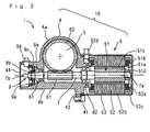
- Figure 2 is a sectional view showing a power transmission device used for the electric power steering device of the present invention.
- a power transmission device 10 having a reduction device and an auxiliary motor which will be discussed later, have been provided in a steering column just like an electric power steering device 1 shown in Figure 1(B).
- a power transmission device 10 having a reduction device and an auxiliary motor which will be described later, may be provided around a pinion shaft of a steering gear 22.
- a steering operation by a driver is detected by a torque sensor (not shown), and the auxiliary motor and the reduction device of the power transmission device 10 promptly generate optimum assist force by calculation performed at a control unit (not shown), thereby achieving comfortable steering feel.
- the power transmission device 10 used for the electric power steering device 1 of the present embodiment has a housing 4 (fixed-side member), through which the steering shaft 3 or a shaft connected to the steering shaft 3 passes.
- the housing 4 comprises a first cylindrical part 4a for permitting the steering shaft 3 or a shaft connected to the steering shaft 3 to penetrate vertically, and a second cylindrical part 4b which intersects the first cylindrical part 4a and extends laterally.
- a worm wheel gear 62 (driven gear) attached to the steering shaft 3 is placed on the first cylindrical part 4a, namely a central rotational shaft of the worm gear 62 or the steering shaft 3 is supported by the housing 4 via a driven-side bearing (not shown), so that the worm gear 62 can rotate integrally with the steering shaft 3.
- the second cylindrical part 4b has openings on both ends.
- a stator case 53 (motor case) is fixed on one of the openings by a bolt 41 via an O ring 42, and a lid 44 is attached to cover the other opening.
- a motor section 5 is constituted by a rotational shaft 7, a rotor 51 attached to an inner end side 7a of the rotational shaft 7, and a stator 52 opposed to the rotor 51.
- stator 52 is fixed on the inner circumferential surface of the stator case 53.
- the stator 52 comprises a core 52b, a winding 52a wound around the core 52b, an insulator 52c for insulating the outer peripheral side of the winding 52a, and a power connector 52d for supplying power to the winding 52a.
- the power connector 52d is also attached to the stator case 53.
- the rotor 51 comprises a yoke 51a which is a part fitted into the rotational shaft 7, a magnet 51b attached to the outer periphery of the yoke 51a, a magnet protector 51c for protecting the outer periphery of the magnet 51b, and a nut 51d for fixing the yoke 51a on the rotational shaft 7.
- a worm gear 61 (driving gear) engaged with the worm wheel gear 62 is attached.
- the worm gear 61 and the worm wheel gear 62 constitute a speed reduction mechanism.
- the rotational shaft 7 is rotatably supported by a first bearing 81, which is a ball bearing held by the second cylindrical part 4b at the distal end side 7b from the worm gear 61, and a second bearing 82, which is a ball bearing held by the housing 4 between the worm gear 61 and the rotor 51 so that the worm gear 61 is sandwiched between the first bearing 81 and the second bearing 82.
- a first bearing 81 which is a ball bearing held by the second cylindrical part 4b at the distal end side 7b from the worm gear 61
- a second bearing 82 which is a ball bearing held by the housing 4 between the worm gear 61 and the rotor 51 so that the worm gear 61 is sandwiched between the first bearing 81 and the second bearing 82.
- a resolver 9 is used as a rotation detector.
- the resolver 9 is placed on the distal end side 7b of the rotational shaft 7.
- the resolver 9 has a resolver rotor 9a (movable member) fitted into the rotational shaft 7, a nut 9b for fixing the resolver rotor 9a on the rotational shaft 7, a resolver stator 9c (detector) positioned opposite to the outer peripheral surface of the resolver rotor 9a, and a resolver connector 9d connected to the resolver stator 9c.
- the resolver stator 9c is pressed and fixed on the inside of the second cylindrical part 4b of the housing 4 by a stator retainer 9e, which is screwed from the opening opposite to the side where the motor section 5 is assembled. Further, a resolver connector 9d is also attached to the second cylindrical part 4b.
- the position of the resolver rotor 9a is changed according to the rotation of the rotational shaft 7.
- the positional change is detected by the resolver stator 9c as a change in impedance and the rotational position of the rotational shaft 7 is detected.
- the rotation of the rotational shaft 7 in the motor section 5 is reduced in speed and transmitted to the steering shaft 3 via the worm gear 61 and the worm wheel gear 62, thereby assisting the operation of the steering wheel 20.
- the motor 5 since the motor 5 has a brushless motor structure, the winding 52a is fed via the resolver 9 based on the detection result of the rotational position of the rotational shaft 7.
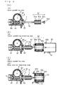
- FIG. 1 A method of manufacturing the electric power steering device 1 according to the present example will be discussed in the following. Regarding the steps of manufacturing the electric power steering device 1 of the present example, Figures 3 to 5 are explanatory views of the steps of manufacturing the power transmission mechanism 10 used for the electric power steering device 1.
- step ST1 of assembling the worm wheel gear shown in Figure 3 (A) the worm wheel gear 62 attached to the steering shaft 3 is set in the housing 4.
- the outer ring of the first bearing 81 is attached to the housing 4 by press-fitting.
- step ST2' of assembling the worm gear shown in Figure 3(B) the worm gear 61 is assembled on the rotational shaft 7 (driving gear assembling step).
- step ST2" of assembling the rotational shaft a round ring 821 is circumferentially caulked on the rotational shaft 7 from the outer circumferential side to fix on the rotational shaft 7, and the second bearing 82 is fixed by press-fitting at a position adjacent to the inner end side 7a with respect to the worm gear 61 on the rotational shaft 7.
- the rotational shaft 7 is passed through an inner ring of the first bearing 81, which is attached to the housing 4, from the distal end side 7b.
- a bearing outer ring retainer 822 threaded on the outer circumferential surface is passed from the inner end side 7a of the rotational shaft 7, and the bearing outer ring retainer 822 is screwed into the second cylindrical part 4b.
- the rotational shaft 7 is rotatably supported by the first bearing 81 and the second bearing 82 that are mounted on the housing 4.
- step ST3 of inspecting engagement of the worm gear shown in Figure 3(C) the rotational shaft 7 is rotated slightly to inspect the engagement between the worm gear 61 and the worm wheel gear 62.
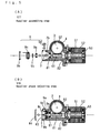
- step ST4 of assembling the rotor shown in Figure 4(A) the rotor 51 is assembled on the rotational shaft 7 from its inner end side 7a, and is fastened by the nut 51d, whereby the rotor 51 is fixedly assembled at a position adjacent to the inner end side 7a of the rotational shaft 7 with respect to the second bearing 82.
- an axial rib for locking is formed by a knurling machining on the inner end side 7a of the rotational shaft 7 where the rotor 51 is assembled.
- step ST5 of preparing assembly of the stator shown in Figure 4(B) after preparation of the core 52b having the winding 52a and the insulator 52c, constituting the stator part 52, attached, the stator case 53 where the power connector 52d is attached, and the bolt 41 for fixing the stator case 53 on the housing case 4, in step ST6' of assembling the stator shown in Figure 4(C), the core 52b is fixed in the stator case 53 and the winding 52a is connected to the power connector 52d. Subsequently, the stator case 53 where the stator 52 is assembled is mounted to the housing 4 via the O ring 42, and the stator case 53 is fixed by the fixing bolt 41. Subsequently, in step ST6" of inspecting the motor section, the rotational shaft 7 is rotated from the outside by using the distal end side 7b of the rotational shaft 7, and the rotational characteristics of the motor 5 are confirmed.
- step ST7 of assembling the resolver shown in Figure 5 (A) the resolver 9 is attached to the distal end side 7b of the rotational shaft 7.
- the resolver rotor 9a is fixed by the nut 9b.
- the resolver stator 9c and the resolver connector 9d are assembled to the housing 4, and the resolver stator 9c is pressed and fixed by the stator retainer 9e after phase of the resolver is adjusted.
- step ST8 of adjusting phase of the resolver shown in Figure 5(B) the resolver stator 9c is connected to the resolver connector 9d, the resolver stator 9c is shifted in the rotating direction, and phase is adjusted. After the phase adjustment, the resolver stator 9c is pressed and fixed by the stator retainer 9e, and a circular opening 43 of the housing 4 is closed by the lid 44, so that the electric power steering device 1 of Figure 1 is completed.
- the power transmission device 10 used for the electric power steering device 1 of the present embodiment uses the motor section 5 comprising the rotational shaft 7, the rotor 51 attached to the inner end side 7a of the rotational shaft 7, and the stator 52 opposed to the rotor 51.
- the power transmission device 10 does not use a motor as a completed product. Therefore, while the conventional art needs to connect the output shaft of the motor and the rotational shaft, on which the worm gear 61 is attached, by spline machining and so on, the present invention only requires the single rotational shaft 7. Thus, it is not necessary to connect shafts by using spline machining and so on. It is therefore possible to reduce the number of components and the manufacturing cost.
- the rotational shaft 7 can be supported by only the two bearings 81 and 82. This naturally reduces the number of components, the manufacturing cost can be reduced, and the device can be made smaller and lighter in weight. Additionally, since the shafts are not connected using spline machining, problems caused by rattling resulting from spline grooves on a connected part, for example, an unusual noise and a reduction in response of the worm gear 61 to the rotation of the motor, do not occur. Besides, the rotational shaft 7 can be supported by only the two bearings 81 and 82 and the steering shaft 3 rotates lightly as a result of the reduced number of the bearings, thereby improving the steering feel.
- step ST3 of inspecting engagement can be accurately performed.
- step ST4 of assembling the rotor since it is possible to perform step ST3 of inspecting engagement before step ST4 of assembling the rotor is performed, when a problem occurs with the worm gear 61 or the worm wheel gear 62, it is possible to easily replace only a gear having the problem.
- the power transmission device 10 is used for the electric power steering device 1
- the worm wheel gear 62 and the worm gear 61 are used as gears, even a small deviation in accuracy is likely to cause a problem in engagement.
- the present embodiment even when such a problem occurs, since the worm wheel gear 62 or the worm gear 61 can be readily replaced in the middle of the manufacturing process, the problem can be readily solved.
- step ST3 of inspecting engagement is performed to solve a problem of engagement before step ST4 of assembling the rotor, thereby improving yield and reliability of the electric power steering device 1.
- step ST6' of assembling the stator the motor section 5 is started and step ST6" of inspecting the motor section can be performed to inspect the motor section 5.
- step ST6" of inspecting the motor section can be performed to inspect the motor section 5.
- step ST6' of assembling the stator the resolver rotor 9a (movable member) for detecting rotation is mounted on the distal end side 7a from the first bearing 81 on the rotational shaft 7, the resolver stator 9c for detecting the rotation of the resolver rotor 9a is attached to the housing 4, and step ST7 of assembling the resolver is performed. Thereafter, step ST8 of adjusting phase is performed.
- step ST8 of adjusting phase is performed at such a time, inspection of an engaged part and the motor. section 5 are completed in the previous step. Hence, problems with an engaged part and the motor section 5 are not found after the phase adjustment. For this reason, it is possible to avoid disassembling after assembling has been performed.
- the cup-shaped stator case 53 is attached to the housing 4.
- a second cylindrical part 4b of a housing 4' may be extended so as to serve as the stator case 53.
- the second cylindrical part 4b of the housing 4' is extended to constitute a cylindrical stator attaching part 53a for fixing a stator 52.
- a power connector 52d is attached to the stator attaching part 53a, and a circular end face 53b of the stator attaching part 53a is covered with a lid 53c.
- the stator attaching part 53a is integrated with the housing 4', thereby omitting components such as an O ring 42 and a fixing nut that are required for attaching the stator case 53.
- the above embodiment described the example in which the power transmission device 10 is used for the electric power steering device 1.
- the present embodiment may be applied to other devices. Further, since the present embodiment uses the resolver 9 for detecting the rotational position of the rotational shaft 7, like the electric power steering device 1 of Figure 1(C), even when the power transmission device 10 is placed at a high temperature around a pinion shaft of a steering gear 22, no thermal problems occur. However, like the electric power steering device 1 of Figure 1(B), when the power transmission device 10 is placed in the steering column, since a temperature does not significantly increase, an optical rotational position detector may be used.
- the first bearing and the second bearing for supporting the rotational shaft have already been fixed on a shared fixed-side member, thereby accurately performing the step of inspecting engagement.
- the step of inspecting engagement can be performed before the step of assembling the rotor, when a problem is found with the driving gear or a driven gear, a gear having a problem can be replaced easily.
- the motor section can be inspected after the inspection step, when a problem is found in this step, it is possible to readily specify that the cause lies in the motor section.
Landscapes
- Engineering & Computer Science (AREA)
- Chemical & Material Sciences (AREA)
- Combustion & Propulsion (AREA)
- Transportation (AREA)
- Mechanical Engineering (AREA)
- Power Engineering (AREA)
- Power Steering Mechanism (AREA)
- Gear Transmission (AREA)
- Brushless Motors (AREA)
- Connection Of Motors, Electrical Generators, Mechanical Devices, And The Like (AREA)
Abstract
Description
Claims (12)
- A power transmission device, comprising:a motor section having a rotational shaft, a rotor attached to an inner end side of the rotational shaft, and a stator positioned opposite to the rotor;a driving gear attached to a distal end side of the rotational shaft with respect to the motor section;a driven gear engaged with the driving gear; anda fixed-side member for rotatably supporting the driven gear, whereinthe rotational shaft is rotatably supported by a first bearing and a second bearing, the first bearing is held by the fixed-side member at a distal end side of the rotational shaft with respect to the driving gear, and the second bearing is held by the fixed-side member between the driving gear and the rotor so that the driving gear is sandwiched between the first bearing and the second bearing.
- The power transmission device according to claim 1, wherein the motor section has a brushless motor structure, and
a movable member for detecting rotation is mounted on a distal end side of the rotational shaft with respect to the first bearing, and
a detector for detecting rotation of the movable member for detecting rotation is mounted on the fixed-side member. - An electric power steering device comprising the power transmission device defined in claim 1 or 2, wherein:the driven gear is a worm wheel gear attached to a side of the steering shaft,the driving gear is a worm gear engaged with the worm wheel gear, andthe motor section is used for assisting steering drive, the motor section assisting rotation of the steering shaft by driving the worm wheel gear to rotate via the worm gear.
- The electric power steering device according to claim 3, wherein the fixed-side member is a housing for covering at least the worm wheel gear and the worm gear.
- The electric power steering device according to claim 4, wherein a motor case for covering the rotor and the stator is connected to the housing.
- The electric power steering device according to claim 4, wherein the housing comprises a cylindrical part for covering the rotor and the stator, and the cylindrical part has an opening covered with a lid.
- A method of manufacturing a power transmission device, which comprises a motor section having a rotational shaft, a rotor attached to an inner end side of the rotational shaft, and a stator positioned opposite to the rotor, a driving gear attached to a distal end side of the rotational shaft with respect to the motor section, a driven gear engaged with the driving gear, and a fixed-side member for rotatably supporting the driven gear, wherein the rotational shaft is rotatably supported by a first bearing and a second bearing, the first bearing is held by the fixed-side member at a distal end side of the rotational shaft with respect to the driving gear, and the second bearing is held by the fixed-side member between the driving gear and the rotor so that the driving gear is sandwiched between the first bearing and the second bearing, the method comprising:a driving gear assembling step of mounting the driving gear on the rotational shaft,a rotational shaft assembling step of engaging the driving gear with the driven gear held by the fixed-side member, supporting a distal end side of the rotational shaft on the fixed-side member via the first bearing, and supporting an inner end side of the rotational shaft on the fixed-side member via the second bearing,a rotor assembling step of attaching the rotor to an inner end side of the rotational shaft, anda stator assembling step of attaching the stator to the fixed-side member opposite to the rotor so as to constitute the motor section.
- The method of manufacturing the power transmission device according to claim 7, wherein the first bearing and the second bearing are ball bearings.
- The method of manufacturing the power transmission device according to claim 7, wherein, after the rotational shaft assembling step, an engagement inspecting step is performed to inspect engagement between the driving gear and the driven gear before the rotor assembling step.
- The method of manufacturing the power transmission device according to claim 7, wherein, after the stator assembling step, the motor section is started and a motor section inspecting step is performed to inspect the motor section.
- The method of manufacturing the power transmission device according to claim 7, wherein the motor section has a brushless motor structure, and
after the stator assembling step, while a movable member of a rotation detecting device is assembled to a distal end side of the rotational shaft with respect to the first bearing, a detector for detecting rotation of the movable member is attached to the fixed-side member, and in this state, a rotation detecting device assembling step is performed to adjust phase of the rotation detecting device. - A method of manufacturing an electric power steering device using the method of manufacturing the power transmission device defined in any one of claims 7 to 11, wherein:the driven gear is a worm wheel gear attached to a side of the steering shaft,the driving gear is a worm gear engaged with the worm wheel gear, andthe motor section is used for assisting steering drive, the motor section assisting rotation of the steering shaft by driving the worm wheel gear to rotate via the worm gear.
Applications Claiming Priority (3)
| Application Number | Priority Date | Filing Date | Title |
|---|---|---|---|
| JP2001306656A JP4121262B2 (en) | 2001-10-02 | 2001-10-02 | Manufacturing method of power transmission device and manufacturing method of electric power steering device |
| JP2001306656 | 2001-10-02 | ||
| PCT/JP2002/010196 WO2003031842A1 (en) | 2001-10-02 | 2002-09-30 | Power transmission device, electric power steering device, and methods of producing the same |
Publications (3)
| Publication Number | Publication Date |
|---|---|
| EP1433975A1 true EP1433975A1 (en) | 2004-06-30 |
| EP1433975A4 EP1433975A4 (en) | 2009-10-28 |
| EP1433975B1 EP1433975B1 (en) | 2010-11-17 |
Family
ID=19126257
Family Applications (1)
| Application Number | Title | Priority Date | Filing Date |
|---|---|---|---|
| EP02800713A Expired - Lifetime EP1433975B1 (en) | 2001-10-02 | 2002-09-30 | Power transmission device, electric power steering device, and methods of producing the same |
Country Status (7)
| Country | Link |
|---|---|
| US (1) | US7243569B2 (en) |
| EP (1) | EP1433975B1 (en) |
| JP (1) | JP4121262B2 (en) |
| CN (1) | CN1295451C (en) |
| DE (1) | DE60238340D1 (en) |
| ES (1) | ES2357056T3 (en) |
| WO (1) | WO2003031842A1 (en) |
Cited By (5)
| Publication number | Priority date | Publication date | Assignee | Title |
|---|---|---|---|---|
| CN105945727A (en) * | 2016-06-20 | 2016-09-21 | 玉林市玉博机械有限公司 | Connecting device for motor and speed reducer with worm and worm gear |
| EP2475078A3 (en) * | 2011-01-11 | 2017-12-20 | Sankyo Seisakusho Co. | Rotating electrical machine and rotating apparatus |
| EP3170706A4 (en) * | 2014-07-15 | 2018-03-28 | Mitsuba Corporation | Brushless wiper motor |
| US10797561B2 (en) | 2014-07-15 | 2020-10-06 | Mitsuba Corporation | Brushless wiper motor |
| US10843664B2 (en) | 2014-07-15 | 2020-11-24 | Mitsuba Corporation | Brushless wiper motor and method for assembling the same |
Families Citing this family (52)
| Publication number | Priority date | Publication date | Assignee | Title |
|---|---|---|---|---|
| JP2004322814A (en) * | 2003-04-24 | 2004-11-18 | Honda Motor Co Ltd | Electric steering device |
| JP2005138670A (en) * | 2003-11-05 | 2005-06-02 | Koyo Seiko Co Ltd | Electric power steering device and electric motor assembling method |
| US7475755B2 (en) * | 2003-11-18 | 2009-01-13 | Jtekt Corporation | Electric power steering device |
| JP4320587B2 (en) * | 2003-11-28 | 2009-08-26 | 株式会社ジェイテクト | Electric power steering apparatus and manufacturing method thereof |
| US20050178608A1 (en) * | 2004-02-17 | 2005-08-18 | Hitachi, Ltd. | Power steering device of electric motor type |
| WO2005123485A1 (en) * | 2004-06-17 | 2005-12-29 | Nsk Ltd. | Steering device for vehicle and method of assembling the same |
| US20060037420A1 (en) * | 2004-08-23 | 2006-02-23 | Yale Industrial Products, Inc. | Mechanical actuator and speed changer combination |
| DE102004042457A1 (en) * | 2004-08-31 | 2006-03-16 | Robert Bosch Gmbh | Gear drive unit |
| CN100511965C (en) * | 2004-11-22 | 2009-07-08 | 株式会社日立制作所 | Motor control apparatus, power steering apparatus and brake control apparatus |
| JP4558478B2 (en) * | 2004-12-28 | 2010-10-06 | 日立オートモティブシステムズ株式会社 | Rotating machine rotor, manufacturing method thereof, and motor for electric power steering |
| WO2007055296A1 (en) * | 2005-11-10 | 2007-05-18 | Nsk Ltd. | Electric power steering device |
| JP4614879B2 (en) * | 2005-12-28 | 2011-01-19 | 株式会社ハーモニック・ドライブ・システムズ | Sealed worm gear type finger joint unit |
| JP5011801B2 (en) * | 2006-04-11 | 2012-08-29 | 日本精工株式会社 | Electric power steering device |
| KR100740704B1 (en) | 2006-04-19 | 2007-07-18 | 동양기전 주식회사 | Motor assembly |
| JP5194528B2 (en) * | 2007-04-06 | 2013-05-08 | 日本精工株式会社 | Power transmission device |
| JP4930179B2 (en) * | 2007-05-09 | 2012-05-16 | 株式会社ジェイテクト | Stepped fitting structure and worm gear support structure |
| US8011265B2 (en) * | 2008-02-11 | 2011-09-06 | Nexteer (Beijing) Technology Co., Ltd. | Modular power actuator |
| EP2251243B1 (en) | 2008-02-12 | 2014-01-29 | JTEKT Corporation | Vehicle steering device |
| JP5397658B2 (en) * | 2008-02-12 | 2014-01-22 | 株式会社ジェイテクト | Vehicle steering apparatus and subassembly transfer method |
| US8549945B2 (en) * | 2008-11-12 | 2013-10-08 | Mando Corporation | Reducer of electronic power steering apparatus |
| JP5603045B2 (en) * | 2009-09-24 | 2014-10-08 | 三菱電機株式会社 | Motor device for electric power steering device |
| DE102009055396A1 (en) * | 2009-12-30 | 2011-07-07 | Robert Bosch GmbH, 70469 | Electric drive with worm gear |
| DE102010041732A1 (en) * | 2010-09-30 | 2012-04-05 | Zf Lenksysteme Gmbh | Steering gear for electrical auxiliary steering system, comprises screw pinion, which has shaft placed in gearbox casing and is drivable by electric motor, where screw pinion engages in helical gear placed in gearbox casing |
| DE102010041744A1 (en) * | 2010-09-30 | 2012-04-05 | Zf Lenksysteme Gmbh | Steering gear with electric motor, control unit and sensor as well as electric power steering system equipped therewith |
| DE102011079527A1 (en) * | 2011-07-21 | 2013-01-24 | Robert Bosch Gmbh | Gear drive means |
| GB201114264D0 (en) | 2011-08-18 | 2011-10-05 | Touch Emas Ltd | Improvements in or relating to prosthetics and orthotics |
| DE102012001389B4 (en) * | 2012-01-26 | 2023-08-03 | Sew-Eurodrive Gmbh & Co Kg | Transmission with a central housing part |
| DE102012001388B4 (en) * | 2012-01-26 | 2023-07-06 | Sew-Eurodrive Gmbh & Co Kg | Transmission with a central housing part |
| GB201302025D0 (en) | 2013-02-05 | 2013-03-20 | Touch Emas Ltd | Improvements in or relating to prosthetics |
| WO2015120083A1 (en) | 2014-02-04 | 2015-08-13 | Rehabilitation Institute Of Chicago | Modular and lightweight myoelectric prosthesis components and related methods |
| GB201403265D0 (en) | 2014-02-25 | 2014-04-09 | Touch Emas Ltd | Prosthetic digit for use with touchscreen devices |
| GB201408253D0 (en) | 2014-05-09 | 2014-06-25 | Touch Emas Ltd | Systems and methods for controlling a prosthetic hand |
| KR102180737B1 (en) * | 2014-08-27 | 2020-11-19 | 엘지이노텍 주식회사 | Motor and power transmission apparatus including the same |
| GB201417541D0 (en) | 2014-10-03 | 2014-11-19 | Touch Bionics Ltd | Wrist device for a prosthetic limb |
| US10619718B2 (en) | 2014-10-09 | 2020-04-14 | Nsk Ltd. | Worm reducer and method of assembling worm reducer |
| US9812924B2 (en) | 2014-11-14 | 2017-11-07 | Steering Solutions Ip Holding Corporation | Motor assembly for an electric power steering assembly |
| KR102557295B1 (en) * | 2015-09-30 | 2023-07-20 | 엘지이노텍 주식회사 | Motor and Brake apparatus having the same |
| CN105292244A (en) * | 2015-11-11 | 2016-02-03 | 吉林大学 | Front wheel independent steering system for commercial vehicle |
| US11185426B2 (en) | 2016-09-02 | 2021-11-30 | Touch Bionics Limited | Systems and methods for prosthetic wrist rotation |
| US10369024B2 (en) | 2016-09-02 | 2019-08-06 | Touch Bionics Limited | Systems and methods for prosthetic wrist rotation |
| CN106505792A (en) * | 2016-12-09 | 2017-03-15 | 上海胜华波汽车电器有限公司 | There is the electric motor of automobile component of double rolling bearing structure |
| CN106809212A (en) * | 2017-03-30 | 2017-06-09 | 福建船政交通职业学院 | One kind is blown out vehicle body stabilizing control system |
| DE102017214523A1 (en) * | 2017-08-21 | 2019-02-21 | Robert Bosch Gmbh | Steering systems for a vehicle |
| JP2019062708A (en) * | 2017-09-28 | 2019-04-18 | 日本電産株式会社 | motor |
| US10973660B2 (en) | 2017-12-15 | 2021-04-13 | Touch Bionics Limited | Powered prosthetic thumb |
| DE102018127204B4 (en) | 2018-10-31 | 2024-12-05 | Knorr-Bremse Systeme für Nutzfahrzeuge GmbH | recirculating ball steering |
| EP4403142B1 (en) | 2019-04-10 | 2025-06-25 | Touch Bionics Limited | Prosthetic digit with articulating links |
| WO2021053557A1 (en) | 2019-09-18 | 2021-03-25 | Touch Bionics Limited | Prosthetic digits and actuators |
| US11931270B2 (en) | 2019-11-15 | 2024-03-19 | Touch Bionics Limited | Prosthetic digit actuator |
| DE102019132590B4 (en) | 2019-12-02 | 2023-01-26 | Audi Ag | Driving device for a vehicle |
| CN111941062B (en) * | 2020-07-15 | 2022-08-12 | 和氏工业技术股份有限公司 | Assembly process of electric power steering gear assembly |
| DE102023210157B4 (en) * | 2023-10-17 | 2025-05-22 | Volkswagen Aktiengesellschaft | Method for producing an electric drive, electric drive and steering system |
Family Cites Families (18)
| Publication number | Priority date | Publication date | Assignee | Title |
|---|---|---|---|---|
| CN88212131U (en) * | 1988-02-06 | 1988-11-23 | 湖南省机械研究所 | Turbine low speed motor |
| JPH02108657A (en) | 1988-10-15 | 1990-04-20 | Showa Denko Kk | Dicyclopentadiene derivative and polymerizable monomer composition containing the derivative |
| JPH02106657A (en) | 1988-10-17 | 1990-04-18 | Gastar Corp | Hot water flow control device for automatic bath device with hot water feeder |
| JPH0342497A (en) | 1989-07-10 | 1991-02-22 | Hitachi Ltd | electric hoist |
| US5186068A (en) * | 1991-06-20 | 1993-02-16 | Peerless-Winsmith, Inc. | Gear reducer with backlash eliminator |
| JPH0819204A (en) | 1994-06-30 | 1996-01-19 | Aisin Seiki Co Ltd | motor |
| US5605071A (en) * | 1995-06-06 | 1997-02-25 | Itt Automotive Electrical Systems, Inc. | Enveloped worm gear clutch wedgelock responsive to reaction force |
| JP2993871B2 (en) | 1995-08-08 | 1999-12-27 | アスモ株式会社 | Worm gear manufacturing method and worm positioning jig used therein |
| EP0861184B1 (en) * | 1995-11-16 | 2000-03-22 | Lucas Industries Limited | Improvements in electric actuators for vehicle systems |
| JPH101058A (en) | 1996-06-13 | 1998-01-06 | Toyota Motor Corp | Reduction mechanism for power steering device |
| GB9619175D0 (en) | 1996-09-13 | 1996-10-23 | Lucas Ind Plc | Electrical power-assisted steering systems |
| JP3493568B2 (en) * | 1997-02-12 | 2004-02-03 | 光洋精工株式会社 | Car steering system |
| GB2327652B (en) * | 1997-05-29 | 2001-04-18 | Nsk Ltd | Electric power assisted steering apparatus |
| JPH11341739A (en) | 1998-05-27 | 1999-12-10 | Jidosha Denki Kogyo Co Ltd | Motor with decelerating mechanism |
| DE19831739A1 (en) | 1998-07-15 | 2000-01-20 | Mannesmann Vdo Ag | Worm gear with an electric motor |
| JP4221825B2 (en) * | 1999-06-28 | 2009-02-12 | 株式会社ジェイテクト | Electric steering device |
| JP2001037159A (en) | 1999-07-21 | 2001-02-09 | Asmo Co Ltd | Actuator and load driving device |
| JP3698605B2 (en) | 2000-01-26 | 2005-09-21 | 光洋精工株式会社 | Electric power steering device |
-
2001
- 2001-10-02 JP JP2001306656A patent/JP4121262B2/en not_active Expired - Fee Related
-
2002
- 2002-09-30 US US10/469,397 patent/US7243569B2/en not_active Expired - Lifetime
- 2002-09-30 EP EP02800713A patent/EP1433975B1/en not_active Expired - Lifetime
- 2002-09-30 CN CNB028055055A patent/CN1295451C/en not_active Expired - Fee Related
- 2002-09-30 ES ES02800713T patent/ES2357056T3/en not_active Expired - Lifetime
- 2002-09-30 WO PCT/JP2002/010196 patent/WO2003031842A1/en not_active Ceased
- 2002-09-30 DE DE60238340T patent/DE60238340D1/en not_active Expired - Lifetime
Cited By (5)
| Publication number | Priority date | Publication date | Assignee | Title |
|---|---|---|---|---|
| EP2475078A3 (en) * | 2011-01-11 | 2017-12-20 | Sankyo Seisakusho Co. | Rotating electrical machine and rotating apparatus |
| EP3170706A4 (en) * | 2014-07-15 | 2018-03-28 | Mitsuba Corporation | Brushless wiper motor |
| US10797561B2 (en) | 2014-07-15 | 2020-10-06 | Mitsuba Corporation | Brushless wiper motor |
| US10843664B2 (en) | 2014-07-15 | 2020-11-24 | Mitsuba Corporation | Brushless wiper motor and method for assembling the same |
| CN105945727A (en) * | 2016-06-20 | 2016-09-21 | 玉林市玉博机械有限公司 | Connecting device for motor and speed reducer with worm and worm gear |
Also Published As
| Publication number | Publication date |
|---|---|
| JP4121262B2 (en) | 2008-07-23 |
| EP1433975B1 (en) | 2010-11-17 |
| CN1492975A (en) | 2004-04-28 |
| WO2003031842A1 (en) | 2003-04-17 |
| EP1433975A4 (en) | 2009-10-28 |
| CN1295451C (en) | 2007-01-17 |
| JP2003113909A (en) | 2003-04-18 |
| US20040065163A1 (en) | 2004-04-08 |
| US7243569B2 (en) | 2007-07-17 |
| DE60238340D1 (en) | 2010-12-30 |
| ES2357056T3 (en) | 2011-04-15 |
Similar Documents
| Publication | Publication Date | Title |
|---|---|---|
| EP1433975B1 (en) | Power transmission device, electric power steering device, and methods of producing the same | |
| JP2972722B2 (en) | Electric steering system | |
| JP4320587B2 (en) | Electric power steering apparatus and manufacturing method thereof | |
| US20070295552A1 (en) | Electric power steering apparatus | |
| JPH11198828A (en) | Electric power steering device | |
| JP2017109654A (en) | Steering device | |
| US8784253B2 (en) | Transmission ratio variable device | |
| JP5141681B2 (en) | Motor, power device and electric power steering device | |
| JP2002249056A (en) | Electric power steering device | |
| JP4270179B2 (en) | Electric power steering device | |
| JP4015310B2 (en) | Electric power steering device | |
| JP2001158368A (en) | Electric power steering device | |
| JP5016237B2 (en) | Electric motor and electric power steering device | |
| JP2013113427A (en) | Method of manufacturing worm gear device | |
| CN121219516A (en) | Gear shift actuator and assembly method | |
| JP4487676B2 (en) | Electric power steering device with variable transmission ratio mechanism | |
| JP2004320842A (en) | Electric power steering device | |
| JP2004132748A (en) | Torque sensor for electric power steering device | |
| JPH10329732A (en) | Rack and pinion steering system | |
| JPH0733034A (en) | Power steering device | |
| JP2005053259A (en) | Cable-type steering device | |
| JP2000326854A (en) | Electric power steering device | |
| JP2000168582A (en) | Electric power steering device | |
| JP2006218922A (en) | Electric power steering device | |
| JP2000118422A (en) | Motor-driven power steering device |
Legal Events
| Date | Code | Title | Description |
|---|---|---|---|
| PUAI | Public reference made under article 153(3) epc to a published international application that has entered the european phase |
Free format text: ORIGINAL CODE: 0009012 |
|
| 17P | Request for examination filed |
Effective date: 20030703 |
|
| AK | Designated contracting states |
Kind code of ref document: A1 Designated state(s): AT BE BG CH CY CZ DE DK EE ES FI FR GB GR IE IT LI LU MC NL PT SE SK TR |
|
| AX | Request for extension of the european patent |
Extension state: AL LT LV MK RO SI |
|
| RAP1 | Party data changed (applicant data changed or rights of an application transferred) |
Owner name: KAYABA INDUSTRY CO., LTD. |
|
| A4 | Supplementary search report drawn up and despatched |
Effective date: 20090924 |
|
| GRAP | Despatch of communication of intention to grant a patent |
Free format text: ORIGINAL CODE: EPIDOSNIGR1 |
|
| RBV | Designated contracting states (corrected) |
Designated state(s): DE ES FR |
|
| GRAS | Grant fee paid |
Free format text: ORIGINAL CODE: EPIDOSNIGR3 |
|
| GRAA | (expected) grant |
Free format text: ORIGINAL CODE: 0009210 |
|
| AK | Designated contracting states |
Kind code of ref document: B1 Designated state(s): DE ES FR |
|
| REF | Corresponds to: |
Ref document number: 60238340 Country of ref document: DE Date of ref document: 20101230 Kind code of ref document: P |
|
| REG | Reference to a national code |
Ref country code: ES Ref legal event code: FG2A Ref document number: 2357056 Country of ref document: ES Kind code of ref document: T3 Effective date: 20110415 |
|
| PLBE | No opposition filed within time limit |
Free format text: ORIGINAL CODE: 0009261 |
|
| STAA | Information on the status of an ep patent application or granted ep patent |
Free format text: STATUS: NO OPPOSITION FILED WITHIN TIME LIMIT |
|
| 26N | No opposition filed |
Effective date: 20110818 |
|
| REG | Reference to a national code |
Ref country code: DE Ref legal event code: R097 Ref document number: 60238340 Country of ref document: DE Effective date: 20110818 |
|
| REG | Reference to a national code |
Ref country code: FR Ref legal event code: PLFP Year of fee payment: 14 |
|
| REG | Reference to a national code |
Ref country code: DE Ref legal event code: R082 Ref document number: 60238340 Country of ref document: DE Representative=s name: SCHMITT-NILSON SCHRAUD WAIBEL WOHLFROM PATENTA, DE Ref country code: DE Ref legal event code: R082 Ref document number: 60238340 Country of ref document: DE Representative=s name: KLUNKER, SCHMITT-NILSON, HIRSCH, DE Ref country code: DE Ref legal event code: R081 Ref document number: 60238340 Country of ref document: DE Owner name: KYB CORPORATION, JP Free format text: FORMER OWNER: KAYABA INDUSTRY CO., LTD., TOKYO, JP |
|
| REG | Reference to a national code |
Ref country code: ES Ref legal event code: PC2A Owner name: KYB CORPORATION Effective date: 20160226 |
|
| REG | Reference to a national code |
Ref country code: FR Ref legal event code: CD Owner name: KYB CORPORATION, JP Effective date: 20160321 |
|
| REG | Reference to a national code |
Ref country code: FR Ref legal event code: PLFP Year of fee payment: 15 |
|
| REG | Reference to a national code |
Ref country code: DE Ref legal event code: R082 Ref document number: 60238340 Country of ref document: DE Representative=s name: SCHMITT-NILSON SCHRAUD WAIBEL WOHLFROM PATENTA, DE |
|
| REG | Reference to a national code |
Ref country code: FR Ref legal event code: PLFP Year of fee payment: 16 |
|
| REG | Reference to a national code |
Ref country code: FR Ref legal event code: PLFP Year of fee payment: 17 |
|
| PGFP | Annual fee paid to national office [announced via postgrant information from national office to epo] |
Ref country code: DE Payment date: 20180920 Year of fee payment: 17 Ref country code: FR Payment date: 20180924 Year of fee payment: 17 |
|
| PGFP | Annual fee paid to national office [announced via postgrant information from national office to epo] |
Ref country code: ES Payment date: 20181022 Year of fee payment: 17 |
|
| REG | Reference to a national code |
Ref country code: DE Ref legal event code: R119 Ref document number: 60238340 Country of ref document: DE |
|
| PG25 | Lapsed in a contracting state [announced via postgrant information from national office to epo] |
Ref country code: DE Free format text: LAPSE BECAUSE OF NON-PAYMENT OF DUE FEES Effective date: 20200401 |
|
| PG25 | Lapsed in a contracting state [announced via postgrant information from national office to epo] |
Ref country code: FR Free format text: LAPSE BECAUSE OF NON-PAYMENT OF DUE FEES Effective date: 20190930 |
|
| REG | Reference to a national code |
Ref country code: ES Ref legal event code: FD2A Effective date: 20210129 |
|
| PG25 | Lapsed in a contracting state [announced via postgrant information from national office to epo] |
Ref country code: ES Free format text: LAPSE BECAUSE OF NON-PAYMENT OF DUE FEES Effective date: 20191001 |