EP1433943A2 - Fuel injection control device - Google Patents
Fuel injection control device Download PDFInfo
- Publication number
- EP1433943A2 EP1433943A2 EP03029472A EP03029472A EP1433943A2 EP 1433943 A2 EP1433943 A2 EP 1433943A2 EP 03029472 A EP03029472 A EP 03029472A EP 03029472 A EP03029472 A EP 03029472A EP 1433943 A2 EP1433943 A2 EP 1433943A2
- Authority
- EP
- European Patent Office
- Prior art keywords
- injection
- injection quantity
- auxiliary
- qtotal
- qbsubtotal
- Prior art date
- Legal status (The legal status is an assumption and is not a legal conclusion. Google has not performed a legal analysis and makes no representation as to the accuracy of the status listed.)
- Withdrawn
Links
- 238000002347 injection Methods 0.000 title claims abstract description 377
- 239000007924 injection Substances 0.000 title claims abstract description 377
- 239000000446 fuel Substances 0.000 title claims abstract description 43
- 238000000034 method Methods 0.000 description 4
- 230000003247 decreasing effect Effects 0.000 description 2
- 238000001514 detection method Methods 0.000 description 2
- XLYOFNOQVPJJNP-UHFFFAOYSA-N water Substances O XLYOFNOQVPJJNP-UHFFFAOYSA-N 0.000 description 2
- 238000002485 combustion reaction Methods 0.000 description 1
- 230000006835 compression Effects 0.000 description 1
- 238000007906 compression Methods 0.000 description 1
- 230000008094 contradictory effect Effects 0.000 description 1
- 238000010586 diagram Methods 0.000 description 1
- 239000002828 fuel tank Substances 0.000 description 1
- 230000006870 function Effects 0.000 description 1
Images

Classifications
-
- F—MECHANICAL ENGINEERING; LIGHTING; HEATING; WEAPONS; BLASTING
- F02—COMBUSTION ENGINES; HOT-GAS OR COMBUSTION-PRODUCT ENGINE PLANTS
- F02D—CONTROLLING COMBUSTION ENGINES
- F02D41/00—Electrical control of supply of combustible mixture or its constituents
- F02D41/30—Controlling fuel injection
- F02D41/38—Controlling fuel injection of the high pressure type
- F02D41/40—Controlling fuel injection of the high pressure type with means for controlling injection timing or duration
- F02D41/402—Multiple injections
-
- Y—GENERAL TAGGING OF NEW TECHNOLOGICAL DEVELOPMENTS; GENERAL TAGGING OF CROSS-SECTIONAL TECHNOLOGIES SPANNING OVER SEVERAL SECTIONS OF THE IPC; TECHNICAL SUBJECTS COVERED BY FORMER USPC CROSS-REFERENCE ART COLLECTIONS [XRACs] AND DIGESTS
- Y02—TECHNOLOGIES OR APPLICATIONS FOR MITIGATION OR ADAPTATION AGAINST CLIMATE CHANGE
- Y02T—CLIMATE CHANGE MITIGATION TECHNOLOGIES RELATED TO TRANSPORTATION
- Y02T10/00—Road transport of goods or passengers
- Y02T10/10—Internal combustion engine [ICE] based vehicles
- Y02T10/40—Engine management systems
Definitions
- the present invention relates to a fuel injection control device of a diesel engine, and more particularly to a fuel injection control device for executing multiple injection by conducting a plurality of auxiliary injections and a main injection within one cycle.
- Diesel engines equipped with a fuel injection control device for executing multiple injection (multiinjection) by conducting a plurality of auxiliary injections and a main injection within one cycle have recently been suggested (for example, Japanese Patent Applications Laid-open Nos. 2000-205021 and 2001-50097).
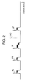
- FIG. 2 shows a drive pulse (current pulse) outputted to a drive circuit of injectors for executing fuel injection with the injectors; in the figure, a crank angle is plotted against the abscissa.
- a total of four injections (three types of auxiliary injections and a main injection) are executed within one cycle.
- a pilot injection PI is carried out at the instant of time prior to the main injection M. This is done for premixing the fuel.
- a pre-injection PR is carried out immediately prior to the main injection M. This is done to produce flame and prevent an ignition delay.
- the main injection M is carried out in the vicinity of compression top dead center TDC, and an after-injection AF is carried out after the main injection M. This is done to burn the non-combusted fuel.
- a post injection is sometimes carried out after the after-injection AF. This is, however, done to improve the treatment capability of an exhaust gas aftertreatment device and makes no contribution to the combustion in the engine. Accordingly, this injection will not be considered herein.
- the injection quantity of each auxiliary injection is determined based on the parameters representing the engine operation state such as engine revolution speed and engine load. For example, the optimum injection quantity of each auxiliary injection is determined by tests conducted in advance for each operation state, and a respective map is created for each auxiliary injection. Then, the injection quantity for each auxiliary injection is determined from the maps based on the parameters such as engine revolution speed and engine load that were actually detected.
- the injection quantity of the main injection is determined as follows.
- injection quantity Qsub of each auxiliary injection assumes a minimum value in the region in which the total injection quantity Qtotal is very small.
- the injection quantity Qsub of auxiliary injections has to be set at a minimum injection quantity of injectors or higher on the map. For example, if the minimum injection quantity of an injector is 2 mm 3 /st, setting has to be made to 2 mm 3 /st even though the optimum injection quantity of auxiliary injection is, for example, 1.6 mm 3 /st.
- the above-described problem sometimes occurs in a region in which the total injection quantity Qtotal is very small.
- the injection quantity Qsub of each auxiliary injection is determined from the map and then corrected based on the water temperature and intake temperature, but the above-described problem sometimes occur when the injection quantity Qsub of each auxiliary injection is incrementally corrected.
- the present invention provides a fuel injection control device for executing multiple injection by conducting a plurality of auxiliary injections and a main injection within one cycle, comprising first means for determining the total injection quantity Qtotal of fuel injected within one cycle based on the parameters representing the engine operation state; second means for determining base injection quantities QBsub of each of the auxiliary injections based on the parameters representing the engine operation state; and third means which, when the sum QBsubtotal of base injection quantities QBsub of each of the auxiliary injections is not larger than the value obtained by multiplying the total injection quantity Qtotal by a coefficient K (0 ⁇ K ⁇ 1), computes the injection quantity QTmain of the main injection by subtracting the sum QBsubtotal from the total injection quantity Qtotal, and when the sum QBsubtotal is larger than the value obtained by multiplying the total injection quantity Qtotal by the coefficient K, computes the injection quantity QTmain of the main injection by reduction correcting the base injection quantities QBsub of the
- the third means may compute a correction coefficient C by dividing the value obtained by multiplying the total injection quantity Qtotal by the coefficient K by the sum QBsubtotal when the sum QBsubtotal of base injection quantities QBsub of each of the auxiliary injections is larger than the value obtained by multiplying the total injection quantity Qtotal by the coefficient K, multiply each of the base injection quantities QBsub of auxiliary injections by the correction coefficient C, and reductionally correct the base injection quantities QBsub of each auxiliary injection at equal ratio.
- the third means may determine the coefficient K based on parameters representing the engine operation state such as engine revolution speed and engine load.
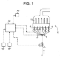
- FIG. 1 is a schematic view of the fuel injection control device of the present embodiment.
- the fuel injection control device of the present embodiment is designed to execute the fuel injection control in a six-cylinder diesel engine E installed on a vehicle.
- a fuel injector (fuel injection valve) 6 is provided in each cylinder of an engine E.
- a high-pressure fuel at a common rail pressure (for example, from several tens to several hundreds of MPa), which is stored in a common rail 7, is constantly supplied to each injector 6.
- Fuel supply into the common rail 7 is carried out by a supply pump 5.
- fuel present in a fuel tank (not shown in the figure) is supplied to the supply pump 5, then pressure is applied to the fuel by the supply pump 5, and the fuel is pumped to the common rail 7.
- the supply pump 5 is a pressure-adjustable pump in which the discharge pressure can be adjusted.
- the discharge pressure of the pump is controlled by a controller 12.
- a pressure sensor 11 is provided in the common rail 7, and the fuel pressure inside the common rail 7 is detected with the pressure sensor 11 and the detected value is inputted into the controller 12.
- the controller 12 conducts the overall control of the device and comprises a CPU for control processing and computation processing and a memory (ROM) for storing control programs, maps, and the like.
- Detection means such as an engine revolution sensor 16 for detecting the revolution speed of the engine E, an accelerator opening degree sensor 17 for detecting the accelerator opening degree in the vehicle, and a crank angle sensor 18 for detecting the angle of a crankshaft (not shown in the figure) of the engine E, are connected to the controller 12.
- the detected values of each detection means 16, 17, and 18 are inputted into the controller 12. Further, the engine revolution sensor 16 and the crank angle sensor 18 may be substantially identical.
- the controller 12 controls the opening/closing of injectors 6 by outputting a drive pulse (current pulse) to a drive circuit (not shown in the figures) of injectors 6 according to the crank angle signal transmitted from the crank angle sensor 18 and controls the injection period and injection quantity of the fuel injected by the injectors 6.
- a fuel injection control device of the present embodiment implements a multiple injection shown in FIG. 2.
- the object of each auxiliary injection was described in the Related Technology section of the specification and the explanation thereof is therefore herein omitted.
- the main injection M and three types of auxiliary injections are executed.
- a controller 12 shown in FIG. 1 stores a map which determines the total injection quantity Qtotal of fuel injected within one cycle for each engine operation state and a map which determines the base injection quantity QBsub of each auxiliary injection (a general term for a base injection quantity QBpi of pilot injection, a base injection quantity QBpr of pre-injection, and a base injection quantity QBaf of after-injection) for each engine operation state.
- the controller 12 stores at least four maps.
- the controller 12 determines the total injection quantity Qtotal of the fuel and the base injection quantity QBsub of each auxiliary injection, and basically determines the target injection quantity QTmain of the main injection by subtracting the sum QBsubtotal of base injection quantities QBsub of each auxiliary injection from the total injection quantity Qtotal of the fuel.
- the injection quantity QBsubtotal of base injection quantities QBsub of each auxiliary injection is corrected with the reduction and the sum QBsubtotal' of base injection quantities QBsub' of auxiliary injections after the correction becomes equal to the value obtained by multiplying the total injection quantity Qtotal by a coefficient K or less than that.
- the target injection quantity QTmain of the main injection is then determined by deducting the sum QBsubtotal' of base injection quantities QBsub' of auxiliary injections after the correction from the total injection quantity Qtotal.
- the coefficient K defines the upper limit of the fraction taken by the sum QBsubtotal of base injection quantities QBsub of auxiliary injections in the total injection quantity Qtotal of fuel injected within one cycle and assumes a value satisfying the formula: 0 ⁇ K ⁇ 1.
- the larger is the coefficient K the larger is the fraction that can be taken by the aforesaid sum QBsubtotal.
- the coefficient K is 0.6
- the injection quantity of auxiliary injections (the aforesaid total QBsubtotal) can take up to 60% of the total injection quantity Qtotal.
- the coefficient K is 1, the entire total injection quantity Qtotal can be taken by the injection quantity of auxiliary injections.
- the coefficient K defines the lower limit of the fraction taken by the injection quantity Qmain of the main injection in the total injection quantity Qtotal.
- the coefficient K is 0.6, at least 40% of the total injection quantity Qtotal is necessarily secured as the injection quantity Qmain of the main injection.
- the coefficient K is 1, the injection quantity Qmain of the main injection sometimes can become 0.
- the coefficient K varies according to the engine operation state.
- the minimum necessary values of the fraction taken by the injection quantity Qmain of the main injection in the total injection quantity Qtotal are found for each engine operation state, for example, by preliminary tests and those values are mapped as the values of coefficient K.
- the controller 12 determines a coefficient K from the map based on the parameters representing the engine operation state, such as the actual engine revolution speed detected by an engine revolution sensor 16 and an actual accelerator opening degree (engine load) detected by an accelerator opening degree sensor 17.
- the coefficient K is not necessarily determined from the map; it may be also found by computation from the parameters representing the engine operation state.
- the sum QBsubtotal of injection quantities QBsub of auxiliary injections is limited (reductionally corrected) so as to become not more than the value obtained by multiplying the total injection quantity Qtotal by a coefficient K. Therefore, the fraction taken by the injection quantity Qmain of the main injection in the total injection quantity Qtotal necessarily becomes larger than the minimum value required for the specific engine operation state.
- the controller 12 determines the total injection quantity Qtotal of fuel injected within one cycle from the map (not shown in the figure) based on the actual engine revolution speed detected by the engine revolution sensor 16, and an actual accelerator opening degree (engine load) detected by the accelerator opening degree sensor 17.
- the controller 12 also determines the base injection quantities QBsub (QBpi, QBpr, QBaf) of each auxiliary injection from the auxiliary injection quantity determination maps M1-M3, based on the total injection quantity Qtotal determined form the map and the actual engine revolution speed Eng rpm detected by the engine revolution sensor 16. Further, because the total injection quantity Qtotal is determined from the engine revolution speed and accelerator opening degree (engine load), it can be also said that the base injection quantity QBsub of each auxiliary injection is determined from the engine revolution speed and engine load.
- the base injection quantity QBsub of auxiliary injection as referred to herein is a value obtained after conducting correction based, e.g., on water temperature and intake temperature in a separate control logic.
- the controller 12 multiplies the total injection quantity Qtotal by the coefficient K in point 2 ⁇ in the figure.
- the quotient D is 1 or more, it means that the aforesaid sum QBsubtotal is not more than the value obtained by multiplying the total injection quantity Qtotal by the coefficient K (QBsubtotal ⁇ K ⁇ Qtotal). In other words, it means that even if the base injection quantity QBsub of auxiliary injections determined from the map is used directly, the fraction of the injection quantity Qtotal of the main injection in the total injection quantity is not less than the lower limit value. Therefore, in this case, 1 is selected as the correction coefficient C. Further, in points 5 ⁇ , 6 ⁇ , 7 ⁇ , the respective base injections QBsub (QBpi, QBpr, QBaf) of each auxiliary injection are multiplied by correction coefficient C.
- the base injections QBsub' (QBpi', QBpr', QBaf') of each auxiliary injection after correction are equal to base injection quantities QBsub prior to correction. Further, those base injections QBsub (QBpi, QBpr, QBaf) of each auxiliary injection are determined as the target injection quantities QTsub (QTpi, QTpr, QTaf) of auxiliary injections.
- the controller 12 outputs a drive pulse to the drive circuit of injectors 6 according to those target injection quantity QTmain of the main injection and target injection quantities QTsub of each auxiliary injection.
- the aforesaid quotient D is less than 1 in point 4 ⁇ shown in the figure, it means that the aforesaid sum QBsubtotal is larger than the value obtained by multiplying the total injection quantity Qtotal by the coefficient K (QBsubtotal > K ⁇ Qtotal).
- the base injection quantities QBsub of auxiliary injections determined from the maps are directly used, it means that the fraction of the injection quantity Qmain of the main injection in the total injection quantity Qtotal became less than the lower limit value.
- the sum QBsubtotal became larger than the total injection quantity Qtotal. Therefore, in this case, the quotient D (D ⁇ 1) is selected as the correction coefficient C.
- the base injection quantities QBsub (QBpi, QBpr, QBaf) of each auxiliary injection are multiplied by correction coefficient C and the base injection quantities QBsub of auxiliary injections are corrected.
- the correction coefficient C is less than 1
- base injections QBsub' (QBpi', QBpr', QBaf') of each auxiliary injection after the correction assume values less than the base injections QBsub prior to correction.
- the base injection values QBsub' of each auxiliary injection are reductionally corrected by respective equal ratios.
- the sum QBsubtotal' of the base injection quantities QBsub' of auxiliary injections after the correction becomes equal to the value (K ⁇ Qtotal) obtained by multiplying the total injection quantity Qtotal by the coefficient K.
- the controller 12 outputs a drive pulse to the drive circuit of injectors 6 according to those target injection quantity QTmain of the main injection and the target injection quantities QTsub (QTpi, QTpr, QTaf) of each auxiliary injection.
- controller 12 of the present embodiment has the functions of the first means, second means, and third means mentioned in the claims.
- the total injection quantity Qtotal determined from the map based on the engine revolution speed Eng rpm and accelerator opening degree is 20 mm 3 /st
- the base injection quantities QBsub of auxiliary injections determined based on the engine revolution speed Eng rpm and the total injection quantity Qtotal are represented by a pilot injection quantity QBpi of 6 mm 3 /st, a pre-injection quantity QBpr of 8 mm 3 /st, and an after-injection quantity QBaf of 10 mm 3 /st.
- the coefficient K determined based on the engine operation state is assumed to be 0.6. In other words, a case is considered in which at least 40% of the total injection quantity Qtotal is wished to be secured as an injection quantity of the main injection.
- the target injection quantity QTmain of the main injection is computed by subtracting the sum QBsubtotal' of the base auxiliary injection quantities Qsub' after the correction from the total injection quantity Qtotal.
- a method for correcting the base injection quantities QBsub of auxiliary injections is not limited to the above-described embodiment. For example, it is not necessary to conduct reduction correction of the base injection quantities QBsub of auxiliary injections at equal ratios, and a priority sequence of the auxiliary injections may be set in advance and a larger subtraction can be applied to those auxiliary injections that have a lower priority sequence. Alternatively, it is also possible to carry out no auxiliary injection with a low priority sequence.
- auxiliary injections are not conducted when the base injection quantities QBsub' of auxiliary injections after the correction are less than the minimum fuel injection quantity of injectors 6.
Landscapes
- Engineering & Computer Science (AREA)
- Chemical & Material Sciences (AREA)
- Combustion & Propulsion (AREA)
- Mechanical Engineering (AREA)
- General Engineering & Computer Science (AREA)
- Electrical Control Of Air Or Fuel Supplied To Internal-Combustion Engine (AREA)
Abstract
Description
Claims (3)
- A fuel injection control device for executing multiple injection by conducting a plurality of auxiliary injections and a main injection within one cycle, comprising:first means for determining a total injection quantity Qtotal of fuel injected within one cycle based on parameters representing an engine operation state;second means for determining base injection quantities QBsub of each of the plurality of auxiliary injection based on the parameters representing the engine operation state; andthird means which, when a sum QBsubtotal of the base injection quantities QBsub of the plurality of auxiliary injections is not larger than a value obtained by multiplying the total injection quantity Qtotal by a coefficient K (0 < K ≦ 1), computes an injection quantity QTmain of the main injection by subtracting the sum QBsubtotal from the total injection quantity Qtotal, and when the sum QBsubtotal is larger than the value obtained by multiplying the total injection quantity Qtotal by the coefficient K, computes the injection quantity QTmain of the main injection by reductionally correcting the base injection quantities QBsub of the plurality of auxiliary injections so that the sum QBsubtotal' of the base injection quantities QBsub' of auxiliary injections after the correction becomes not larger than the value obtained by multiplying the total injection quantity Qtotal by the coefficient K, and by subtracting the sum QBsubtotal' after the correction from the total injection quantity Qtotal.
- The fuel injection control device according to claim 1, characterized in that the third means, when the sum QBsubtotal of base injection quantities Qsub of the auxiliary injections is larger than the value obtained by multiplying the total injection quantity Qtotal by the coefficient K, computes a correction coefficient C by dividing the value obtained by multiplying the total injection quantity Qtotal by the coefficient K by the sum QBsubtotal, multiplies each of the base injection quantities QBsub of auxiliary injections by the correction coefficient C, and reduction corrects the base injection quantities QBsub of the auxiliary injection by an equal amount.
- The fuel injection control device according to claim 1 or 2, characterized in that the third means determines the coefficient K based on the parameters representing the engine operation state such as engine revolution speed and engine load.
Applications Claiming Priority (2)
| Application Number | Priority Date | Filing Date | Title |
|---|---|---|---|
| JP2002374327A JP2004204765A (en) | 2002-12-25 | 2002-12-25 | Fuel injection control device |
| JP2002374327 | 2002-12-25 |
Publications (2)
| Publication Number | Publication Date |
|---|---|
| EP1433943A2 true EP1433943A2 (en) | 2004-06-30 |
| EP1433943A3 EP1433943A3 (en) | 2005-08-10 |
Family
ID=32463536
Family Applications (1)
| Application Number | Title | Priority Date | Filing Date |
|---|---|---|---|
| EP03029472A Withdrawn EP1433943A3 (en) | 2002-12-25 | 2003-12-19 | Fuel injection control device |
Country Status (3)
| Country | Link |
|---|---|
| US (1) | US6826470B2 (en) |
| EP (1) | EP1433943A3 (en) |
| JP (1) | JP2004204765A (en) |
Families Citing this family (6)
| Publication number | Priority date | Publication date | Assignee | Title |
|---|---|---|---|---|
| JP4603921B2 (en) * | 2005-04-01 | 2010-12-22 | ヤンマー株式会社 | Fuel injection control method for internal combustion engine |
| US7296555B2 (en) * | 2005-08-25 | 2007-11-20 | General Electric Company | System and method for operating a turbo-charged engine |
| JP2009074369A (en) * | 2007-09-18 | 2009-04-09 | Toyota Motor Corp | Fuel injection system |
| US8082730B2 (en) * | 2008-05-20 | 2011-12-27 | Caterpillar Inc. | Engine system having particulate reduction device and method |
| JP6007568B2 (en) * | 2012-04-20 | 2016-10-12 | トヨタ自動車株式会社 | Fuel injection control device for internal combustion engine |
| US10570840B2 (en) | 2018-02-08 | 2020-02-25 | Ford Global Technologies, Llc | System and method generating an exotherm in an exhaust system |
Family Cites Families (8)
| Publication number | Priority date | Publication date | Assignee | Title |
|---|---|---|---|---|
| US4196702A (en) * | 1978-08-17 | 1980-04-08 | General Motors Corporation | Short duration fuel pulse accumulator for engine fuel injection |
| JPH11173200A (en) | 1997-12-08 | 1999-06-29 | Toyota Motor Corp | Fuel injection control device for internal combustion engine |
| JP2000205021A (en) | 1999-01-07 | 2000-07-25 | Nissan Motor Co Ltd | Fuel injection control device for diesel engine |
| IT1308412B1 (en) * | 1999-03-05 | 2001-12-17 | Fiat Ricerche | METHOD OF COMBUSTION CONTROL OF A DIRECT INJECTION DIESEL ENGINE THROUGH THE IMPLEMENTATION OF MULTIPLE INJECTIONS USING A SYSTEM |
| US6125823A (en) * | 1999-05-27 | 2000-10-03 | Detroit Diesel Corporation | System and method for controlling fuel injections |
| JP3721873B2 (en) * | 1999-08-03 | 2005-11-30 | いすゞ自動車株式会社 | Engine fuel injection control device |
| DE10064495A1 (en) * | 2000-12-22 | 2002-07-04 | Bosch Gmbh Robert | Method of injecting fuel in an internal combustion engine using consecutive injection steps |
| ITTO20020143A1 (en) * | 2002-02-19 | 2003-08-19 | Fiat Ricerche | METHOD AND INJECTION CONTROL DEVICE IN AN INTERNAL COMBUSTION ENGINE, IN PARTICULAR A DIESEL ENGINE EQUIPPED WITH A SYSTEM |
-
2002
- 2002-12-25 JP JP2002374327A patent/JP2004204765A/en active Pending
-
2003
- 2003-12-18 US US10/741,286 patent/US6826470B2/en not_active Expired - Fee Related
- 2003-12-19 EP EP03029472A patent/EP1433943A3/en not_active Withdrawn
Also Published As
| Publication number | Publication date |
|---|---|
| EP1433943A3 (en) | 2005-08-10 |
| US6826470B2 (en) | 2004-11-30 |
| JP2004204765A (en) | 2004-07-22 |
| US20040133334A1 (en) | 2004-07-08 |
Similar Documents
| Publication | Publication Date | Title |
|---|---|---|
| US7055503B2 (en) | Fuel injection controller for engine | |
| JP3966096B2 (en) | Injection amount control device for internal combustion engine | |
| JP4588971B2 (en) | Method and apparatus for controlling an internal combustion engine | |
| CN100398798C (en) | Device and method for controlling fuel injection in an internal combustion engine | |
| EP1561936A2 (en) | Control system for internal combustion engine | |
| JP2010255444A (en) | Fuel injection control device and method for internal combustion engine | |
| JP2005155601A (en) | Injection amount control device for internal combustion engine | |
| JP2008309036A (en) | Fuel estimation device | |
| EP1766217A1 (en) | Fuel injection control apparatus for internal combustion engine | |
| US10113499B2 (en) | Fuel injection control device for internal combustion engine | |
| JP5519410B2 (en) | Fuel supply device for internal combustion engine | |
| JP3985602B2 (en) | Injection rate control device for internal combustion engine | |
| US6826470B2 (en) | Fuel injection control device | |
| US7343900B2 (en) | Ignition timing controller of internal combustion engine | |
| US6961651B2 (en) | Common rail fuel injection device | |
| JP3876766B2 (en) | Injection rate control device for internal combustion engine | |
| JP4670771B2 (en) | Fuel injection control device | |
| JP2010019108A (en) | Fuel injection controller of internal combustion engine | |
| JP4206759B2 (en) | Fuel injection control device | |
| US6612297B2 (en) | Method of controlling an engine startup | |
| JP4637036B2 (en) | Control device for internal combustion engine | |
| JP3968905B2 (en) | Engine fuel injection control device | |
| US20060150962A1 (en) | Air-fuel ratio feedback control apparatus for engines | |
| JP3674066B2 (en) | Fuel injection control device for internal combustion engine | |
| JP2010138754A (en) | Fuel injection control device for internal combustion engine |
Legal Events
| Date | Code | Title | Description |
|---|---|---|---|
| PUAI | Public reference made under article 153(3) epc to a published international application that has entered the european phase |
Free format text: ORIGINAL CODE: 0009012 |
|
| AK | Designated contracting states |
Kind code of ref document: A2 Designated state(s): AT BE BG CH CY CZ DE DK EE ES FI FR GB GR HU IE IT LI LU MC NL PT RO SE SI SK TR |
|
| AX | Request for extension of the european patent |
Extension state: AL LT LV MK |
|
| PUAL | Search report despatched |
Free format text: ORIGINAL CODE: 0009013 |
|
| AK | Designated contracting states |
Kind code of ref document: A3 Designated state(s): AT BE BG CH CY CZ DE DK EE ES FI FR GB GR HU IE IT LI LU MC NL PT RO SE SI SK TR |
|
| AX | Request for extension of the european patent |
Extension state: AL LT LV MK |
|
| 17P | Request for examination filed |
Effective date: 20051229 |
|
| AKX | Designation fees paid |
Designated state(s): AT BE BG CH CY CZ DE DK EE ES FI FR GB GR HU IE IT LI LU MC NL PT RO SE SI SK TR |
|
| STAA | Information on the status of an ep patent application or granted ep patent |
Free format text: STATUS: THE APPLICATION HAS BEEN WITHDRAWN |
|
| 18W | Application withdrawn |
Effective date: 20070625 |