Cross-Reference to Related Application
This application claims priority to Provisional Application Serial No.
60/436,123, filed December 23, 2002.
Field of the Invention
The present invention relates to aluminum alloys, and more particularly
relates to aluminum sheet products in which alloy compositions and processing
methods are controlled in order to produce improved crash resistance properties.
Background of the Invention
The use of aluminum sheet in automotive applications has generally
been limited to Aluminum Association 6xxx alloys (Al-Mg-Si) for outer panels and
5xxx alloys (Al-Mg) for inner panels and structural members. In order to maximize
the weight savings potential of aluminum, it is desirable to replace relatively low
strength 5xxx alloys in the structure with higher strength 6xxx alloys. However, a
shortcoming of existing 6xxx auto body sheet (ABS) alloys is their ability to absorb
energy during crash situations. This is generally termed crashworthiness.
Autobody sheet requires a combination of good forming properties along
with good strength after paint baking operations. The forming properties require good
stretch forming and good bending. This traditionally has been achieved with rapid
water quenching from solution heat treat temperatures. However, rapid water
quenching often results in distortion, surface irregularities and water staining that are
unacceptable for outer auto body applications. Air quenching offers many advantages
over water quenching with respect to eliminating quench distortion problems, but air
quenching can lead to poor bending performance.
The present invention has been developed in view of the foregoing and
to address other deficiencies of the prior art.
Summary of the Invention
The present invention controls alloy compositions and quench rates to
produce aluminum alloy sheet products exhibiting good as-processed formability and
shape, and good crashworthiness and strength in the artificially aged condition.
An aspect of the invention is to provide a 6xxx alloy with a desired
combination of strength and crashworthiness.
Another aspect of the present invention is to provide a heat treated and
slow quenched aluminum alloy sheet comprising from about 0.5 to about 0.7 wt.% Si,
from about 0.5 to about 0.7 wt.% Mg, from about 0.1 to about 0.3 wt.% Mn, and the
balance Al and incidental impurities.
A further aspect of the present invention is to provide a method of
treating an aluminum alloy sheet, the method comprising providing a heat treated
aluminum alloy sheet comprising Si, Mg, Mn, and the balance aluminum and
incidental impurities, and slow quenching the heat treated aluminum sheet at a rate of
less than about 200°F/second.
These and other aspects of the present invention will be more apparent
from the following description.
Brief Description of the Drawings
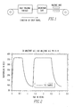
Fig. 1 is a schematic diagram illustrating an aluminum sheet heat
treating and slow quenching process in accordance with an embodiment of the present
invention.
Fig. 2 is a graph of temperature versus time for a paint bake treatment.
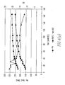
Fig. 3 is a graph of yield strength versus line speed of a continuous heat
treat furnace, illustrating strength properties for two different 6xxx alloys without a
slow quench and with a slow quench in accordance with embodiments of the present
invention.
Figs. 4a and 4b are graphs of tensile properties versus paint bake time at
185°C for two different alloys.
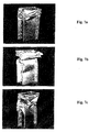
Figs. 5a-5c are computer generated illustrations taken from different
views of a sample crash box made of alloy 6060 sheet without a slow quench.
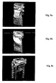
Figs. 6a-6c are computer generated illustrations taken from different
views of a sample crash box made of alloy 6xxA sheet with a slow quench.
Figs. 7a-7c are computer generated illustrations taken from different
views of a sample crash box made of alloy 6060 sheet with a slow quench.
Figs. 8a-8c are computer generated illustrations taken from different
views of a sample crash box made of alloy 6xxA sheet without a slow quench.
Detailed Description of Preferred Embodiments
The present invention provides aluminum alloy sheet products having
favorable crash resistant properties. As used herein, the term "sheet" refers to
aluminum alloy products having thicknesses from 0.2 to 6.3 mm. For auto body sheet
products, thicknesses of from 0.7 to 3.5 mm are preferred. The aluminum alloy sheet
products exhibit favorable crash resistance or crashworthiness properties. For the
purpose of this invention, crashworthiness is defined as the ability of a material to
absorb energy by plastic deformation without appreciable cracking. The
crashworthiness of the sheet products can be quantified by critical fracture strain
(CFS).
A preferred process path includes the following steps: casting of an
aluminum alloy ingot by conventional or continuous methods; hot rolling; intermediate
annealing; cold rolling; solution heat treating; and slow quenching, e.g., air quench or
minimum distortion water quench. The steps of solution heat treating and slow
quenching preferably occur on a continuous heat treater or temper line. After slow
quenching, the sheet may optionally be reheated and coil cooled. The optional cooling
step may be performed as an off-line batch process. The steps of solution heat treating
and slow quenching, in addition to an optional reheating step, are schematically
illustrated in Fig. 1.
In the solution heat treatment step, the aluminum alloy sheet may be run
through a continuous heat treater to substantially dissolve soluble phases formed
during upstream processing. This process typically involves furnace temperatures of
800 to 1,100°F at speeds from 20 to 150 feet per minute. The temperature and dwell
time in the furnace may be adjusted based upon alloy composition and gauge.
In the slow quenching step, upon exit from the furnace zone of the
continuous heat treater, the sheet is quenched at a controlled rate to retain the solute in
solid solution. This can be accomplished, for example, with air or minimum distortion
water. An aspect of this invention is the use of relatively slow quench rates that
minimize sheet distortion while still developing favorable physical properties. As
used herein, the term "slow quench" means quenching at a rate of less than about
200°F/second, preferably less than about 100°F/second. Quench rates for air type
processes preferably range from about 20 to about 100°F/second, more preferably
from about 40 to about 70°F/second. Water quench rates preferably range from 50 to
1,000°F/sec, more preferably from 100 to 200°F/second.
In the optional reheating step, a heating unit may follow the quench unit
and any coil handling equipment, preferably just ahead of the coiling equipment on the
exit end of the line. The heating unit raises the temperature of the sheet such that an
elevated coiling temperature can be achieved. A preferred range of coiling
temperatures is from about 130 to about 190°F. In the coil cooling step, the warm coil
is allowed to cool slowly, typically as a 5,000 to 50,000 lb. mass of metal. This
typically results in cooling rates of from about 0.1 to about 5°F/hour.
In accordance with an embodiment of the present invention, the
composition of the aluminum alloy sheet is controlled in order to provide favorable
crash resistance properties. The Si and Mg levels are controlled in order to provide
high strengths. The Mn level is sufficient to control the grain size of the sheet,
particularly during heat treating. Suitable alloys include 6xxx alloys such as 6009,
6060, 6063 and 6005. Typical, preferred and more preferred alloy composition ranges
are listed in Table 1.
| Alloy Compositions (Wt.%) |
| | Si | Mg | Mn | Fe | Cu | Al |
| Typical | 0.5-0.7 | 0.5-0.7 | 0.1-0.3 | 0.35 max | 0.20 max | balance |
| Preferred | 0.56-0.68 | 0.54-0.66 | 0.12-0.18 | 0.15-0.30 | 0.10 max | balance |
| More Preferred | 0.58-0.66 | 0.56-0.64 | 0.12-0.18 | 0.15-0.25 | 0.10 max | balance |
A particularly preferred Al-Mg-Si-Mn alloy is listed in Table 2. Table 2
lists the preferred 6xxA alloy compositions and a 6060 alloy composition in
wt.percentages, with the balance comprising aluminum and incidental impurities.
| Aluminum Alloy Sheet Compositions |
| Alloy | | Si % | Fe % | Cu % | Mn % | Mg % |
| 6xxA | target | 0.62 | 0.20 | - | 0.15 | 0.60 |
| min. | 0.58 | 0.15 | - | 0.12 | 0.56 |
| max. | 0.66 | 0.25 | 0.10 | 0.18 | 0.64 |
| 6060 | target | 0.56 | 0.20 | 0.075 | - | 0.55 |
| min. | 0.53 | 0.15 | 0.05 | - | 0.52 |
| max. | 0.58 | 0.25 | 0.10 | 0.10 | 0.57 |
An advantage of the present invention is the improvement in the
crashworthiness of the aluminum alloy sheet product, which may be measured by
critical fracture strain (CFS) and axial crush tests. Using the typical engineering
stress-strain output from a standard r&n tension test, a critical fracture strain can be
determined:
CFS = -ln(let,eng)
in which et,eng represents the total engineering thinning strain. The total engineering
thinning strain is a function of em, Φm and Φf:
γt,eng = f(em, Φm, Φf)
where em is the engineering strain at the maximum load; Φm is the engineering stress at
the maximum load; and Φf is the engineering stress at the fracture load.
The following engineering assumptions are made in the development of
the CFS: strains in the thickness and width directions are the same before the
maximum load (Pmax); the true stress after Pmax is a constant; and the width strain is
constant after Pmax. The total thinning strain at fracture may therefore be determined.
In accordance with the present invention, a minimum CFS crashworthiness value of
about 15 is preferred, with a value of at least 18 being more preferred.
A typical property comparison for alloys is shown in Table 3.
| Alloy | Yield Strength | Crush Results | CFS |
| 5083 | 145 MPa | Good with some cracking on tight folds | 18 |
| 6060 | 216 MPa | Good with some cracking at geometric constraints | 21 |
| 6xxA | 244 MPa | Good with some cracking at tight folds | 18 |
Twelve lots of materials 2.0 mm thick were fabricated. Details of the
fabrication are given in Table 4. Prior to hot rolling, each of the cast samples was
scalped and preheated at 590°C for 8 hours followed by 560°C for 9 hours. The main
variables were alloy composition, use of a slow spray quench at an approximate
cooling rate of 150°F/second following hot rolling, and the line speed of the
continuous heat treat furnace (CHT). The compositions of the two 6xxA and 6060
alloys studied are shown above in Table 2.
| STEP | Coil | 1 6xxA | Coil | 2 6xxA | Coil | 3 6060 | Coil 4 6060 |
| Hot Rolling | 1080 x 10 mm | 1080 x 8 mm | 1080 x 10 mm | 1080 x 8 mm |
| Hot Rolling exit t. °C | >450°C | >450°C | >450°C | >450°C |
| Slow Quench after hot rolling | YES | NO | YES | NO |
| SHT Cont. Furnace | 550-570-570 °C spray bar | 550-570-570 °C spray bar | 550-570-570 °C spray bar | 550-570-570 °C spray bar |
| Speed |
| 1 | 7 mt/min | 5 mt/min | 7 mt/min | 5 mt/min |
| Speed |
| 2 | 11 mt/min | 8 mt/min | 11 mt/min | 8 mt/min |
| Speed |
| 3 | 15 mt/min | 12 mt/min | 15 mt/min | 12 mt/min |
The sheet was evaluated in the as received T4 temper and also after a
simulative paint bake treatment at 180°C (365°F). Fig. 2 is a temperature-time plot of
a thermocoupled sheet sample during the paint bake treatment.
| Tensile Properties for Sheet Products in T4 Temper |
| Alloy | Slow Quench | Speed | Test | Rm | ASTM Test Rp0.2 | A | Uniform A | r | n |
| Coil | | (m/min) | direction | (MPa) | (MPa) | (%) | (%) |
| 6060 | No | 12 | L | 164 | 95 | 29 | 24 | 0.43 | 0.225 |
| | | | X | 155 | 94 | 22 | 21 | 0.518 | 0.221 |
| | | | T | 152 | 88 | 30 | 25 | 0.749 | 0.215 |
| | | 8 | L | 184 | 108 | 28 | 23 | 0.634 | 0.23 |
| | | | X | 182 | 106 | 23 | 22 | 0.634 | 0.222 |
| | | | T | 178 | 104 | 25 | 19 | 0.749 | 0.227 |
| | | 5 | L | 192 | 116 | 26 | 21 | 0.749 | 0.223 |
| | | | X | 189 | 115 | 27 | 19 | 0.518 | 0.216 |
| | | | T | 191 | 116 | 26 | 21 | 0.685 | 0.22 |
| 6060 | Yes | 15 | L | 183 | 113 | 28 | 25 | 0.595 | 0.216 |
| | | | X | 187 | 110 | 25 | 21 | 0.518 | 0.24 |
| | | | T | 185 | 108 | 25 | 20 | 0.749 | 0.232 |
| | | 11 | L | 180 | 111 | 30 | 24 | 0.411 | 0.219 |
| | | | X | 183 | 109 | 27 | 22 | 0.277 | 0.216 |
| | | | T | 183 | 112 | 27 | 22 | 0.214 | 0.216 |
| | | 7 | L | 187 | 115 | 27 | 21 | 0.427 | 0.223 |
| | | | X | 186 | 113 | 26 | 21 | 0.346 | 0.223 |
| | | | T | 188 | 112 | 26 | 20 | 0.267 | 0.224 |
| 6xxA | No | 12 | L | 163 | 94 | 28 | 24 | 0.629 | 0.231 |
| | | | X | 167 | 90 | 23 | 21 | 0.634 | 0.243 |
| | | | T | 159 | 91 | 25 | 20 | 0.629 | 0.222 |
| | | 8 | L | 196 | 109 | 28 | 22 | 0.629 | 0.246 |
| | | | X | 192 | 109 | 25 | 21 | 0.518 | 0.24 |
| | | | T | 189 | 105 | 25 | 21 | 0.629 | 0.247 |
| | | 5 | L | 209 | 116 | 27 | 22 | 0.634 | 0.246 |
| | | | X | 204 | 119 | 24 | 20 | 0.518 | 0.238 |
| | | | T | 200 | 113 | 25 | 18 | 0.629 | 0.233 |
| 6xxA | Yes | 15 | L | 196 | 118 | 28 | 20 | 0.518 | 0.228 |
| | | | X | 194 | 118 | 28 | 21 | 0.343 | 0.224 |
| | | | T | 188 | 114 | 25 | 21 | 0.429 | 0.215 |
| | | 11 | L | 210 | 128 | 28 | 22 | 0.477 | 0.229 |
| | | | X | 209 | 129 | 26 | 22 | 0.477 | 0.225 |
| | | | T | 203 | 125 | 23 | 18 | 0.524 | 0.218 |
| | | 7 | L | 208 | 125 | 26 | 21 | 0.682 | 0.232 |
| | | | X | 209 | 124 | 26 | 21 | 0.687 | 0.234 |
| | | | T | 207 | 124 | 24 | 20 | 0.525 | 0.233 |
The tensile properties of the sheet in the T4 temper are presented in
Table 5. There was a slight tendency for the T4 yield strength to decrease with
increasing CHT line speed, which is probably indicative of incomplete dissolution of
Mg2Si at the faster line speed. Minor variations in other T4 properties were found.
Guided bend tests using T4 sheet pre-strained 10% show that the slow
quench is beneficial to bending of both alloys. Both alloys fabricated using the slow
quench withstood the maximum sharp bend. Downflange and hemming tests illustrate
that both alloys are flat hem capable.
The sheet r&n tensile properties after the paint bake were measured
using 2 inch gage length specimens. Table 6 lists the r&n tensile data.
| Tensile Properties for Sheet Products after Paint Bake |
| Alloy | Slow Quench | CHT LineSpeed meters/min | r&n test data (L - direction after PB) |
| | | | YS
(MPa) | UTS
(MPa) | YS/UTS | Uniform Elong.
(%) | Total Elong.
(%) | r (avg) | n |
| 6060 | No | 5 avg | 237 | 247 | 0.96 | 10.3 | 15.2 | 1.0064 | 0.0850 |
| 239 | 249 | 10.4 | 16.1 | 0.9614 | 0.0845 |
| 238 | 248 | 10.4 | 15.7 | 0.9839 | 0.0848 |
| 6060 | No | 8 avg | 230 | 238 | 0.97 | 10.1 | 15.5 | 0.9403 | 0.0906 |
| 230 | 239 | 11.0 | 15.4 | 0.9982 | 0.0910 |
| 230 | 238 | 10.6 | 15.5 | 0.9693 | 0.0908 |
| 6060 | No | 12 avg | 197 | 206 | 0.95 | 9.3 | 15.3 | 0.9267 | 0.0958 |
| 192 | 201 | 9.7 | 15.0 | 0.9657 | 0.0976 |
| 194 | 204 | 9.5 | 15.2 | 0.9462 | 0.0967 |
| 6xxA | Yes | 7 avg | 236 | 243 | 0.97 | 10.2 | 17.1 | 0.7234 | 0.0897 |
| 235 | 243 | 10.9 | 16.2 | 0.7301 | 0.0912 |
| 236 | 243 | 10.6 | 16.7 | 0.7268 | 0.0905 |
| 6xxA | Yes | 11 avg | 237 | 245 | 0.97 | 10.3 | 17.0 | 0.7626 | 0.0919 |
| 237 | 244 | 10.7 | 18.0 | 0.7448 | 0.0913 |
| 237 | 244 | 10.5 | 17.5 | 0.7537 | 0.0916 |
| 6xxA | Yes | 15 avg | 228 | 235 | 0.97 | 10.1 | 15.6 | 0.8057 | 0.0917 |
| 228 | 234 | 10.5 | 16.4 | 0.8491 | 0.0923 |
| 228 | 234 | 10.3 | 16.0 | 0.8274 | 0.0920 |
| 6060 | Yes | 7 avg | 237 | 245 | 0.96 | 10.0 | 16.4 | 0.7026 | 0.0831 |
| 237 | 246 | 9.9 | 14.7 | 0.7120 | 0.0830 |
| 237 | 246 | 10.0 | 15.6 | 0.7073 | 0.0831 |
| 6060 | Yes | 11 avg | 239 | 247 | 0.97 | 10.4 | 15.6 | 0.6590 | 0.0822 |
| 236 | 245 | 10.3 | 16.9 | 0.6609 | 0.0839 |
| 238 | 246 | 10.4 | 16.3 | 0.6600 | 0.0831 |
| 6060 | Yes | 15 avg | 236 | 245 | 0.97 | 10.0 | 15.2 | 0.6953 | 0.0804 |
| 237 | 245 | 10.1 | 16.5 | 0.6594 | 0.0815 |
| 237 | 245 | 10.1 | 15.9 | 0.6774 | 0.0810 |
| 6xxA | No | 5 avg | 249 | 257 | 0.97 | 9.8 | 14.8 | 1.0046 | 0.0832 |
| 248 | 256 | 9.9 | 16.4 | 0.9965 | 0.0831 |
| 249 | 256 | 9.9 | 15.6 | 1.0006 | 0.0832 |
| 6xxA | No | 8 avg | 232 | 241 | 0.97 | 10.3 | 16.3 | 1.0856 | 0.0904 |
| 231 | 239 | 10.3 | 16.0 | 1.0917 | 0.0896 |
| 232 | 240 | 10.3 | 16.2 | 1.0887 | 0.0900 |
| 6xxA | No | 12 avg | 165 | 176 | 0.94 | 10.1 | 16.4 | 1.0024 | 0.1137 |
| 172 | 18 | 10.3 | 16.1 | 0.9479 | 0.1060 |
| 169 | 2179 | 10.2 | 16.3 | 0.9752 | 0.1099 |
Fig. 3 plots yield strength of the alloys as a function of the processing
variables. The yield strength has the tendency to decrease at the fastest CHT line
speeds due to incomplete dissolution of Mg2Si. Guinier x-ray data showed the
presence of Mg2Si in the materials processed at the faster line speeds. The influence
of line speed on yield strength is most pronounced in the sheet which was processed
without using the slow quench.
Fig. 4a is a graph of Rm, Rp0.2 and A values versus paint bake time at
185°C for the 6060 sample listed in Table 6 which was subjected to the slow quench
and a CHT speed of 11 meters/minute. Fig. 4b is a similar graph for the 6xxA sample
which was likewise subjected to the slow quench and CHT speed of 11 meters/minute.
Crash boxes were assembled having a rectangular cross section
measuring 63 mm by 133 mm. Welds or rivets may be used at approximately 1 inch
on center with the first and last weld approximately ½ inch from the end. The number
of spot welds or rivets specified were 20 per flange. An adhesive sold under the
designation Betamate 1494 by Gurit Essex is a one-component toughened epoxy that
is applied warm along the side seams of the crash boxes, followed by riveting. A
pneumatic heated cartridge gun is used to dispense the adhesive at approximately 40 to
50°C (104 to 122°F). The metal components to be joined were also heated to
approximately the same temperature to assist in application of the adhesive and
improve flow and wettability. The adhesive was applied to warm metal on the flanges
just prior to spot welding or riveting. Rivets were installed at the same locations
specified for welding. End caps are then welded in place. After assembly, the boxes
were paint baked. The paint baked boxes were tested in axial crush. The crush loads
and energy absorbed at displacements of 100, 150, and 200 mm is given in Table 7.
| Axial Crush Test Results of Paint Baked Samples |
| Sample No. | Alloy | Slow Quench | CHT Line Speed meters/min | Crush (after PB) |
| | | | | Max Load | Mean Load | Energy Absorbed @ (J) |
| | | | | (kN) | (J/mm) | 100 mm | 150 mm | 200 mm |
| 1 | 6060 | No | 8 avg | 144.7 | 55.7 | 5941 | 8472 | 11039 |
| 144.4 | 56.5 | 6011 | 8470 | 11184 |
| 144.9 | 52.8 | 5935 | 8746 | 10470 |
| 144.7 | 55.0 | 5962 | 8563 | 10898 |
| 2 | 6xxA | Yes | 11 avg | 156.3 | 54.9 | 6380 | 8364 | 10877 |
| 152.8 | 58.6 | 6323 | 8955 | 11602 |
| 157.0 | 53.4 | 6171 | 8496 | 10571 |
| 155.4 | 55.6 | 6291 | 8605 | 11017 |
| | 6xxA | Yes | 11 avg | 162.2 | 58.4 | 5932 | 9146 | 11563 |
| 162.2 | 51.1 | 5505 | 8000 | 10119 |
| 156.9 | 57.3 | 6690 | 9149 | 11361 |
| 160.4 | 55.6 | 6042 | 8765 | 11014 |
| 3 | 6060 | Yes | 11 avg | 154.6 | 50.4 | 6076 | 7924 | 9983 |
| 141.4 | 53.8 | 6205 | 8449 | 10670 |
| 140.6 | 51.9 | 5554 | 8028 | 10278 |
| 145.5 | 52.0 | 5945 | 8134 | 10310 |
| | 6060 | Yes | 11 avg | 149.1 | 56.4 | 5771 | 8977 | 11170 |
| 148.1 | 55.7 | 6081 | 8644 | 11045 |
| 153.1 | 52.3 | 6437 | 8175 | 10364 |
| 150.1 | 54.8 | 6096 | 8599 | 10860 |
| 4 | 6xxA | No | 8 avg | 140.0 | 51.3 | 5752 | 8257 | 10156 |
| 147.8 | 55.6 | 5724 | 8469 | 11020 |
| 143.8 | 52.8 | 5992 | 8461 | 10455 |
| 143.9 | 53.2 | 5823 | 8396 | 10544 |
Computer generated illustrations of the crushed appearance of the boxes
are shown in Figs. 5-8. Figs. 5a-c are computer generated illustrations from different
view of Sample No. 1 listed in Table 7. Figs. 6a-c are computer generated illustrations
of Sample No. 2. Figs. 7a-c are computer generated illustrations of Sample No. 3.
Figs. 8a-c are computer generated illustrations of Sample No. 4. There were no
significant differences among the quantifiable crush parameters for the samples tested.
The performance of the materials met the goals of a sheet alloy product
for use in crash critical applications. The paint baked sheet had yield strengths of
about 235 MPa, total elongation of 15% and good static crush performance. The T4
properties indicate acceptable formability.
Whereas particular embodiments of this invention have been described
above for purposes of illustration, it will be evident to those skilled in the art that
numerous variations of the details of the present invention may be made without
departing from the invention as defined in the appended claims.