EP1433676A2 - Sensorvorrichting zur Erfassung der Benetzung einer transparenten Scheibe - Google Patents
Sensorvorrichting zur Erfassung der Benetzung einer transparenten Scheibe Download PDFInfo
- Publication number
- EP1433676A2 EP1433676A2 EP03012392A EP03012392A EP1433676A2 EP 1433676 A2 EP1433676 A2 EP 1433676A2 EP 03012392 A EP03012392 A EP 03012392A EP 03012392 A EP03012392 A EP 03012392A EP 1433676 A2 EP1433676 A2 EP 1433676A2
- Authority
- EP
- European Patent Office
- Prior art keywords
- radiation
- transmitter
- guiding means
- sensor device
- housing
- Prior art date
- Legal status (The legal status is an assumption and is not a legal conclusion. Google has not performed a legal analysis and makes no representation as to the accuracy of the status listed.)
- Granted
Links
- 239000011521 glass Substances 0.000 title description 2
- 230000005855 radiation Effects 0.000 claims abstract description 56
- 238000009736 wetting Methods 0.000 claims abstract description 8
- 230000008878 coupling Effects 0.000 claims description 15
- 238000010168 coupling process Methods 0.000 claims description 15
- 238000005859 coupling reaction Methods 0.000 claims description 15
- 239000004033 plastic Substances 0.000 claims description 4
- 230000003595 spectral effect Effects 0.000 claims description 4
- 230000001419 dependent effect Effects 0.000 claims description 2
- 238000005259 measurement Methods 0.000 description 8
- 230000008901 benefit Effects 0.000 description 7
- 238000013461 design Methods 0.000 description 5
- 238000001514 detection method Methods 0.000 description 3
- XLYOFNOQVPJJNP-UHFFFAOYSA-N water Substances O XLYOFNOQVPJJNP-UHFFFAOYSA-N 0.000 description 2
- 230000000052 comparative effect Effects 0.000 description 1
- 230000007423 decrease Effects 0.000 description 1
- 230000000694 effects Effects 0.000 description 1
- 238000005516 engineering process Methods 0.000 description 1
- 238000011156 evaluation Methods 0.000 description 1
- 230000006872 improvement Effects 0.000 description 1
- 238000002347 injection Methods 0.000 description 1
- 239000007924 injection Substances 0.000 description 1
- 238000001746 injection moulding Methods 0.000 description 1
- 230000007794 irritation Effects 0.000 description 1
- 238000004519 manufacturing process Methods 0.000 description 1
- 238000012986 modification Methods 0.000 description 1
- 230000004048 modification Effects 0.000 description 1
- 239000002985 plastic film Substances 0.000 description 1
- 229920006255 plastic film Polymers 0.000 description 1
- 230000009467 reduction Effects 0.000 description 1
- 239000007921 spray Substances 0.000 description 1
- 238000004381 surface treatment Methods 0.000 description 1
- 238000012549 training Methods 0.000 description 1
Images

Classifications
-
- B—PERFORMING OPERATIONS; TRANSPORTING
- B60—VEHICLES IN GENERAL
- B60S—SERVICING, CLEANING, REPAIRING, SUPPORTING, LIFTING, OR MANOEUVRING OF VEHICLES, NOT OTHERWISE PROVIDED FOR
- B60S1/00—Cleaning of vehicles
- B60S1/02—Cleaning windscreens, windows or optical devices
- B60S1/04—Wipers or the like, e.g. scrapers
- B60S1/06—Wipers or the like, e.g. scrapers characterised by the drive
- B60S1/08—Wipers or the like, e.g. scrapers characterised by the drive electrically driven
- B60S1/0818—Wipers or the like, e.g. scrapers characterised by the drive electrically driven including control systems responsive to external conditions, e.g. by detection of moisture, dirt or the like
- B60S1/0822—Wipers or the like, e.g. scrapers characterised by the drive electrically driven including control systems responsive to external conditions, e.g. by detection of moisture, dirt or the like characterized by the arrangement or type of detection means
- B60S1/0833—Optical rain sensor
- B60S1/0837—Optical rain sensor with a particular arrangement of the optical elements
-
- B—PERFORMING OPERATIONS; TRANSPORTING
- B60—VEHICLES IN GENERAL
- B60S—SERVICING, CLEANING, REPAIRING, SUPPORTING, LIFTING, OR MANOEUVRING OF VEHICLES, NOT OTHERWISE PROVIDED FOR
- B60S1/00—Cleaning of vehicles
- B60S1/02—Cleaning windscreens, windows or optical devices
- B60S1/04—Wipers or the like, e.g. scrapers
- B60S1/06—Wipers or the like, e.g. scrapers characterised by the drive
- B60S1/08—Wipers or the like, e.g. scrapers characterised by the drive electrically driven
- B60S1/0818—Wipers or the like, e.g. scrapers characterised by the drive electrically driven including control systems responsive to external conditions, e.g. by detection of moisture, dirt or the like
- B60S1/0822—Wipers or the like, e.g. scrapers characterised by the drive electrically driven including control systems responsive to external conditions, e.g. by detection of moisture, dirt or the like characterized by the arrangement or type of detection means
-
- G—PHYSICS
- G01—MEASURING; TESTING
- G01N—INVESTIGATING OR ANALYSING MATERIALS BY DETERMINING THEIR CHEMICAL OR PHYSICAL PROPERTIES
- G01N21/00—Investigating or analysing materials by the use of optical means, i.e. using sub-millimetre waves, infrared, visible or ultraviolet light
- G01N21/17—Systems in which incident light is modified in accordance with the properties of the material investigated
- G01N21/55—Specular reflectivity
- G01N21/552—Attenuated total reflection
Definitions
- the invention relates to a sensor device for Detection of wetting on a transparent pane with at least one radiation transmitter and at least a radiation receiver in a sensor housing are arranged, with refractive radiation guiding means are provided, the radiation emitted by the transmitter couple into the disc and one of the wetting of the Disc-dependent part of the coupled radiation with total reflection on at least one surface of the Uncouple the disc from the disc.
- Such sensors are usually in a housing housed in the wiping area of the wiper blades is attached to the inside of the windshield.
- the basic principle of a rain sensor is based on the fact that light, especially light in the infrared spectral range, from emitted by a transmitter and via refractive radiation guiding means, for example lenses in the windshield is coupled. With a suitable coupling angle it happens on the outer surface of the windshield, that is, when the radiation from optically denser medium (glass of the windshield) for optically thinner medium (outside air) for total reflection. The total reflected light is used by other refractive ones Radiation guiding means, for example further lenses, coupled out of the disc and a radiation receiver fed.
- the degree of total reflection that is The proportion of the total reflected light depends on the degree of wetting of the pane. Is namely the Example a drop of water in the area where the Transmitter emitted light onto the outer surface of the Disc falls, the difference in the refractive indices decreases the media on either side of the interface what leads to changed total reflection conditions.
- the evaluation unit connected downstream of the receiver registers the Changes in the total reflected radiation and from this calculates the current degree of wetting respectively the appropriate control parameters for the Wiper system.
- the senor As mentioned, in the area of the windshield is appropriate, it is desirable to do so to be as small as possible to give the driver's view not restrict unnecessarily. On the other hand, requires a precise measurement as strong as possible Signal around statistical as well as amplifier noise if possible to reduce. It is therefore generally attempted to build a transmitter as small as possible on the one hand, on the other hand, however, the largest possible proportion of his emitted light for the measurement and at the same time, the housing dimensions are as small as possible hold.
- DE 199 55 432 A1 describes a generic device known, in which the facing the disc Wall of the housing at least partially transparent is designed and lenses for coupling and decoupling the Light in and out of the panes in one piece with this Housing wall are formed.
- a coupling lens is arranged in the immediate vicinity of a transmitter, so that a large proportion of that emitted by this transmitter Light can be picked up by the coupling lens.
- the device according to the invention according to claim 1 builds on the state of the art in that further reflective Radiation guidance means are provided the radiation components emitted by the transmitter, which of the refractive radiation means are not directly detected will feed it indirectly. This makes possible it to efficiently use those parts of the light that in known measuring devices are lost. By appropriate coordination of the symmetries of the refractive and the reflective radiation guide can even an almost complete use of the emitted by the transmitter Light can be achieved.
- the invention is particularly useful according to claim 2 Designed in such a way because the aforementioned advantages thereby in an analogous manner to the part on the receiver side the device can be transmitted. Because it will possible because a larger proportion of the Decoupling lens from the disc coupled light Is made accessible to the recipient, which in addition the Accuracy or the speed of the measurement increases.
- the embodiment according to claim 6 leads to a particularly inexpensive implementation of the invention Sensor device because the housing parts, for example, as Plastic injection molded parts can be formed at which the desired reflective radiation guide in a short, subsequent surface treatment step can be created.
- the advantage of the embodiment according to claim 7 is in that the training of the refractive radiation guide as plastic lenses analogous to the one before Said a particularly inexpensive design of the Allows sensor device.
- Radiation guidance means according to claim 8 is a further reduction in sensor volume achieved. moreover can reflective radiation guide means in this embodiment have simpler structures because the acceptance angle of the staircase-like Structure is larger than that of conventional lenses.
- the special choice of the type of radiation according to claim 9 offers two advantages. Firstly, there is generation and detection of infrared light, especially with the preferably used SMD technology, particularly simple and inexpensive. The other is this spectral range out of visibility for the driver, so that irritation from the sensor is excluded are.
- Figure 1 shows a schematic plan view of a first Embodiment of the sensor device according to the invention. It is described below together with FIG. 2 be a schematic cross section through the same Sensor device along the section line II - II represents.
- the sensor device is in two parts Housing 10, 20 arranged.
- Figure 1 shows the view on the surface 23, which in the case of assembly with the not shown Disc is in contact. This area is Part of the housing part 20.
- an electronic circuit board 30 is arranged, on the two infrared transmitters 31 and two infrared receivers 32 are arranged.
- Transmitter 31 and a receiver 32 is a pair of lenses arranged, each consisting of a coupling lens 21 and a decoupling lens 22.
- the coupling lens 21 is used Recording of the one emitted by the assigned infrared transmitter Light and the coupling into the disc under one suitable angle.
- the decoupling lens 22 takes that from portion of the light totally reflected on and passes it on to the assigned recipient.
- the arrows in Figure 1 illustrate the essential direction the radiation guidance.
- FIG. 2 there are radiation components by dashed lines indicated that emitted by a transmitter 31 be, but with conventional sensor devices not taken up by the coupling lens 21 and into the Disc are coupled. Are symmetrical about this radiation components also by dashed lines indicated by the decoupling lens 22 from the Disc to be decoupled in conventional sensor devices but do not reach the receiver 32.
- radiation components are from Housing surfaces 14, 24 embodied concave mirror elements caught and on the coupling lens 21 and from the decoupling lens 22 to the receiver 32. You can therefore contribute to the measurement of what the signal level and thus the accuracy or the maximum speed of measurement increased significantly.
- the concave mirror elements are made of mirrored wall components both housing parts 10, 20 together. she thus only develop their effect when assembled. This modular structure enables a particularly space-saving Design of the sensor device and a inexpensive manufacturing.
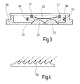
- Figure 3 shows a schematic cross section through a second embodiment of the sensor device according to the invention.
- the same reference symbols stand for functional same elements as in Figures 1 and 2.
- the elements of the reflective radiation guiding means but not as part of the housing. Rather, they are designed as a separate component that between the board 30 and the lenses 21, 22 respectively the housing wall 23 is inserted. This can for example in the form of a suitably designed one Insert sheet or a mirrored plastic film respectively.
- a central plane mirror element 25 provided that not only the above already explained purpose of the reflective radiation guiding means fulfilled, but also as an aperture between serves the transmitter 31 and the receiver 32, the undesirable Scattered radiation of the transmitter 31 from the receiver 32 keeps away and so a further improvement of the measurement quality allows.
- Figure 4 shows a special embodiment of the refractive Radiation guidance means, in particular a coupling device 21, is.
- the coupling device 21 instead of being a classic lens the coupling device 21 as a transparent, staircase-like Trained structure that has the same function as a classic lens, namely the coupling of the from Transmitter 31 emits light into the pane, but is flatter and can be formed over a large area and thus overall is space-saving and particularly efficient.
- a analog structure can of course also for the Coupling of the totally reflected light from the pane be used.
Landscapes
- Engineering & Computer Science (AREA)
- Automation & Control Theory (AREA)
- Mechanical Engineering (AREA)
- Investigating Or Analysing Materials By Optical Means (AREA)
Abstract
Description
- Figur 1
- eine schematische Draufsicht auf eine Ausführungsform der erfindungsgemäßen Sensorvorrichtung;
- Figur 2
- einen schematischen Querschnitt durch die erfindungsgemäße Sensorvorrichtung von Figur 1 entlang der Schnittlinie II - II in Figur 1;
- Figur 3
- einen schematischen Querschnitt durch eine zweite Ausführungsform der erfindungsgemäßen Sensorvorrichtung; und
- Figur 4
- eine schematische Detaildarstellung einer besonderen Ausführungsform der refraktiven Strahlungsführungsmittel.
Claims (9)
- Sensorvorrichtung zur Erfassung einer Benetzung auf einer transparenten Scheibe mit wenigstens einem Strahlungssender (31) und wenigstens einem Strahlungsempfänger (32), die in einem Sensorgehäuse (10, 20) angeordnet sind, wobei refraktive Strahlungsführungsmittel (21, 22, 26) vorgesehen sind, die vom Sender (31) emittierte Strahlung in die Scheibe einkoppeln und einen von der Benetzung der Scheibe abhängigen Teil der eingekoppelten Strahlung unter Totalreflexion an wenigstens einer Oberfläche der Scheibe aus der Scheibe auskoppeln und dem Empfänger (32) zuführen, dadurch gekennzeichnet, dass weitere reflektive Strahlungsführungsmittel (14, 24, 25) vorgesehen sind, die vom Sender (31) emittierte Strahlungsanteile, welche von den refraktiven Strahlungsführungsmitteln (21, 22, 26) nicht unmittelbar erfasst werden, diesen mittelbar zuführen.
- Sensorvorrichtung nach Anspruch 1, dadurch gekennzeichnet, dass zusätzliche reflexive Strahlungsführungsmittel (21, 22, 26) vorgesehen sind, die aus der Scheibe ausgekoppelte Strahlungsanteile, welche von dem Empfänger (32) nicht unmittelbar erfasst werden, diesem mittelbar zuführen.
- Sensorvorrichtung nach einem der Ansprüche 1 oder 2, dadurch gekennzeichnet, dass die reflektiven Strahlungsführungsmittel (14, 24) wenigstens bereichsweise als Teil des Gehäuses (10, 20) ausgestaltet sind.
- Sensorvorrichtung nach Anspruch 3, dadurch gekennzeichnet, dass das Gehäuse aus wenigstens zwei miteinander verbindbaren Gehäuseteilen (10, 20) besteht, von denen jedes im Zusammenbauzustand zusammenwirkende Bestandteile der reflektiven Strahlungsführungsmittel (14, 24) trägt.
- Sensorvorrichtung nach einem der vorangehenden Ansprüche, dadurch gekennzeichnet, dass die reflektiven Strahlungsführungsmittel (24, 25) wenigstens bereichsweise als separates Bauteil in das Gehäuse (10) einlegbar sind.
- Sensorvorrichtung nach einem der vorangehenden Ansprüche, dadurch gekennzeichnet, dass die reflektiven Strahlungsführungsmittel als die vom Sender (31) emittierte Strahlung reflektierend beschichtete Kunststoffoberflächen (14, 24, 25) ausgestaltet sind.
- Sensorvorrichtung nach einem der vorangehenden Ansprüche, dadurch gekennzeichnet, dass die refraktiven Strahlungsführungsmittel als für die vom Sender emittierte Strahlung transparente Kunststofflinsen (21, 22) ausgestaltet sind.
- Sensorvorrichtung nach einem der Ansprüche 1 bis 6, dadurch gekennzeichnet, dass die refraktiven Strahlungsführungsmittel als treppenartige Struktur (26) einer für die vom Sender emittierte Strahlung transparenten Gehäusewandung (23) ausgeführt sind.
- Sensorvorrichtung nach einem der vorangehenden Ansprüche, dadurch gekennzeichnet, dass der Sender (31) Licht im infraroten Spektralbereich aussendet und der Empfänger (32) für Licht dieses Spektralbereichs empfindlich ist.
Applications Claiming Priority (2)
| Application Number | Priority Date | Filing Date | Title |
|---|---|---|---|
| DE10261923A DE10261923A1 (de) | 2002-12-23 | 2002-12-23 | Sensorvorrichtung zur Erfassung der Benetzung einer transparenten Scheibe |
| DE10261923 | 2002-12-23 |
Publications (3)
| Publication Number | Publication Date |
|---|---|
| EP1433676A2 true EP1433676A2 (de) | 2004-06-30 |
| EP1433676A3 EP1433676A3 (de) | 2005-03-09 |
| EP1433676B1 EP1433676B1 (de) | 2006-08-09 |
Family
ID=32404428
Family Applications (1)
| Application Number | Title | Priority Date | Filing Date |
|---|---|---|---|
| EP03012392A Expired - Lifetime EP1433676B1 (de) | 2002-12-23 | 2003-05-30 | Sensorvorrichtung zur Erfassung der Benetzung einer transparenten Scheibe |
Country Status (3)
| Country | Link |
|---|---|
| EP (1) | EP1433676B1 (de) |
| DE (2) | DE10261923A1 (de) |
| ES (1) | ES2271423T3 (de) |
Cited By (2)
| Publication number | Priority date | Publication date | Assignee | Title |
|---|---|---|---|---|
| WO2008063363A1 (en) | 2006-11-16 | 2008-05-29 | Pilkington North America, Inc. | Multi-mode rain sensor |
| WO2008089807A1 (de) * | 2007-01-26 | 2008-07-31 | Valeo Schalter Und Sensoren Gmbh | Sensormodul zur detektion von aerosolen und/oder regentropfen und betriebsverfahren hierfür |
Families Citing this family (3)
| Publication number | Priority date | Publication date | Assignee | Title |
|---|---|---|---|---|
| DE102006045916B4 (de) * | 2006-09-28 | 2010-03-18 | Pepperl + Fuchs Gmbh | Lichttaster oder Lichtschranke zum Nachweis von Objekten und Testverfahren für den Verschmutzungsgrad eines Lichttasters oder einer Lichtschranke |
| JP4826620B2 (ja) * | 2008-10-29 | 2011-11-30 | 株式会社デンソー | 光検出装置 |
| DE202012003277U1 (de) | 2012-03-22 | 2012-07-11 | Iris-Gmbh Infrared & Intelligent Sensors | Erkennung von Signalstörungen eines optischen Sensors hervorgerufen durch Beschädigungen oder Verdeckungen |
Citations (1)
| Publication number | Priority date | Publication date | Assignee | Title |
|---|---|---|---|---|
| DE19955423A1 (de) | 1999-11-18 | 2001-05-31 | Hella Kg Hueck & Co | Sensoreinrichtung und Verfahren zur Herstellung einer Sensoreinrichtung |
Family Cites Families (2)
| Publication number | Priority date | Publication date | Assignee | Title |
|---|---|---|---|---|
| DE19713910C1 (de) * | 1997-04-04 | 1998-07-30 | Kostal Leopold Gmbh & Co Kg | Optoelektronische Sensoreinrichtung |
| DE19821335C2 (de) * | 1997-04-04 | 2000-07-13 | Kostal Leopold Gmbh & Co Kg | Optoelektronische Sensoreinrichtung |
-
2002
- 2002-12-23 DE DE10261923A patent/DE10261923A1/de not_active Withdrawn
-
2003
- 2003-05-30 DE DE50304564T patent/DE50304564D1/de not_active Expired - Lifetime
- 2003-05-30 ES ES03012392T patent/ES2271423T3/es not_active Expired - Lifetime
- 2003-05-30 EP EP03012392A patent/EP1433676B1/de not_active Expired - Lifetime
Patent Citations (1)
| Publication number | Priority date | Publication date | Assignee | Title |
|---|---|---|---|---|
| DE19955423A1 (de) | 1999-11-18 | 2001-05-31 | Hella Kg Hueck & Co | Sensoreinrichtung und Verfahren zur Herstellung einer Sensoreinrichtung |
Cited By (3)
| Publication number | Priority date | Publication date | Assignee | Title |
|---|---|---|---|---|
| WO2008063363A1 (en) | 2006-11-16 | 2008-05-29 | Pilkington North America, Inc. | Multi-mode rain sensor |
| US7847255B2 (en) * | 2006-11-16 | 2010-12-07 | Pilkington North America, Inc. | Multi-mode rain sensor |
| WO2008089807A1 (de) * | 2007-01-26 | 2008-07-31 | Valeo Schalter Und Sensoren Gmbh | Sensormodul zur detektion von aerosolen und/oder regentropfen und betriebsverfahren hierfür |
Also Published As
| Publication number | Publication date |
|---|---|
| DE50304564D1 (de) | 2006-09-21 |
| EP1433676A3 (de) | 2005-03-09 |
| EP1433676B1 (de) | 2006-08-09 |
| DE10261923A1 (de) | 2004-07-01 |
| ES2271423T3 (es) | 2007-04-16 |
Similar Documents
| Publication | Publication Date | Title |
|---|---|---|
| EP0981470B2 (de) | Optischer sensor | |
| EP1424252B1 (de) | Optischer Sensor | |
| DE69510270T2 (de) | Regentropfensensor, Scheibenwischeranlage mit einem derartigen Sensor und damit ausgerüstetes Kraftfahrzeug | |
| DE3735267C3 (de) | Vorrichtung zur Sichtweitenmessung | |
| DE102010031005B4 (de) | Lichterfassungsvorrichtung zum Erfassen von Licht, das sich um ein Fahrzeug herum ausbreitet | |
| DE3926228C2 (de) | ||
| DE19700665A1 (de) | Sensor zum Detektieren von Fremdmaterial und Scheibenwischsystem mit Sensor zum Detektieren von Fremdmaterial | |
| DE102008054388A1 (de) | Lichtsensor zum Erfassen von Helligkeit | |
| EP1068112A1 (de) | Regensensor | |
| EP1101673A2 (de) | Sensoreinrichtung und Verfahren zur Herstellung einer Sensoreinrichtung | |
| DE102006008274B4 (de) | Kraftfahrzeug mit einer optischen Erfassungsvorrichtung und Verfahren zum Betreiben eines Kraftfahrzeugs | |
| EP1519861B1 (de) | Regensensor, insbesondere für ein kraftfahrzeug | |
| EP1433676B1 (de) | Sensorvorrichtung zur Erfassung der Benetzung einer transparenten Scheibe | |
| DE3825663A1 (de) | Sensorvorrichtung zur feststellung des vorhandenseins von wassertroepfchen auf einer fahrzeug-scheibe und mit der sensorvorrichtung arbeitendes scheibenwischer-steuergeraet | |
| DE19846969A1 (de) | Regensensor | |
| DE102005010657B4 (de) | Objekterfassungsvorrichtung | |
| DE10339696A1 (de) | Vorrichtung zur Erfassung von Objekten auf einer transparenten Wand, insbesondere von Regentropfen auf einer Windschutzscheibe | |
| EP1149745A1 (de) | Vorrichtung zur Reinigung von optoelektronischen Sensorsystemen | |
| EP1908652B1 (de) | Regensensor | |
| EP1514750B1 (de) | Kombinierte Sensoranordnung zur Detektion von Umgebungslicht und Regen | |
| EP1585977B1 (de) | Sensor zur detektion von nebelartigen medien | |
| EP1346889B1 (de) | Regensensor, insbesondere für Scheiben | |
| DE10049851C1 (de) | Vorrichtung zum Erkennen der strahlungsmäßigen Durchlässigkeit von vor Sensoren angebrachten Elementen | |
| EP1598247A2 (de) | Regensensor | |
| EP1431143A2 (de) | Regensensor, insbesondere für ein Kraftfahrzeug |
Legal Events
| Date | Code | Title | Description |
|---|---|---|---|
| PUAI | Public reference made under article 153(3) epc to a published international application that has entered the european phase |
Free format text: ORIGINAL CODE: 0009012 |
|
| AK | Designated contracting states |
Kind code of ref document: A2 Designated state(s): AT BE BG CH CY CZ DE DK EE ES FI FR GB GR HU IE IT LI LU MC NL PT RO SE SI SK TR |
|
| AX | Request for extension of the european patent |
Extension state: AL LT LV MK |
|
| PUAL | Search report despatched |
Free format text: ORIGINAL CODE: 0009013 |
|
| AK | Designated contracting states |
Kind code of ref document: A3 Designated state(s): AT BE BG CH CY CZ DE DK EE ES FI FR GB GR HU IE IT LI LU MC NL PT RO SE SI SK TR |
|
| AX | Request for extension of the european patent |
Extension state: AL LT LV MK |
|
| 17P | Request for examination filed |
Effective date: 20050909 |
|
| AKX | Designation fees paid |
Designated state(s): DE ES FR GB IT SE |
|
| GRAP | Despatch of communication of intention to grant a patent |
Free format text: ORIGINAL CODE: EPIDOSNIGR1 |
|
| GRAS | Grant fee paid |
Free format text: ORIGINAL CODE: EPIDOSNIGR3 |
|
| GRAA | (expected) grant |
Free format text: ORIGINAL CODE: 0009210 |
|
| AK | Designated contracting states |
Kind code of ref document: B1 Designated state(s): DE ES FR GB IT SE |
|
| PG25 | Lapsed in a contracting state [announced via postgrant information from national office to epo] |
Ref country code: IT Free format text: LAPSE BECAUSE OF FAILURE TO SUBMIT A TRANSLATION OF THE DESCRIPTION OR TO PAY THE FEE WITHIN THE PRESCRIBED TIME-LIMIT;WARNING: LAPSES OF ITALIAN PATENTS WITH EFFECTIVE DATE BEFORE 2007 MAY HAVE OCCURRED AT ANY TIME BEFORE 2007. THE CORRECT EFFECTIVE DATE MAY BE DIFFERENT FROM THE ONE RECORDED. Effective date: 20060809 |
|
| REG | Reference to a national code |
Ref country code: GB Ref legal event code: FG4D Free format text: NOT ENGLISH |
|
| REF | Corresponds to: |
Ref document number: 50304564 Country of ref document: DE Date of ref document: 20060921 Kind code of ref document: P |
|
| REG | Reference to a national code |
Ref country code: SE Ref legal event code: TRGR |
|
| GBT | Gb: translation of ep patent filed (gb section 77(6)(a)/1977) |
Effective date: 20061115 |
|
| ET | Fr: translation filed | ||
| REG | Reference to a national code |
Ref country code: ES Ref legal event code: FG2A Ref document number: 2271423 Country of ref document: ES Kind code of ref document: T3 |
|
| PLBE | No opposition filed within time limit |
Free format text: ORIGINAL CODE: 0009261 |
|
| STAA | Information on the status of an ep patent application or granted ep patent |
Free format text: STATUS: NO OPPOSITION FILED WITHIN TIME LIMIT |
|
| 26N | No opposition filed |
Effective date: 20070510 |
|
| PGFP | Annual fee paid to national office [announced via postgrant information from national office to epo] |
Ref country code: SE Payment date: 20091222 Year of fee payment: 8 |
|
| PGFP | Annual fee paid to national office [announced via postgrant information from national office to epo] |
Ref country code: GB Payment date: 20100324 Year of fee payment: 8 |
|
| PGFP | Annual fee paid to national office [announced via postgrant information from national office to epo] |
Ref country code: ES Payment date: 20100520 Year of fee payment: 8 |
|
| PGFP | Annual fee paid to national office [announced via postgrant information from national office to epo] |
Ref country code: IT Payment date: 20100527 Year of fee payment: 8 |
|
| REG | Reference to a national code |
Ref country code: SE Ref legal event code: EUG |
|
| GBPC | Gb: european patent ceased through non-payment of renewal fee |
Effective date: 20110530 |
|
| PG25 | Lapsed in a contracting state [announced via postgrant information from national office to epo] |
Ref country code: IT Free format text: LAPSE BECAUSE OF NON-PAYMENT OF DUE FEES Effective date: 20110530 |
|
| PG25 | Lapsed in a contracting state [announced via postgrant information from national office to epo] |
Ref country code: GB Free format text: LAPSE BECAUSE OF NON-PAYMENT OF DUE FEES Effective date: 20110530 |
|
| REG | Reference to a national code |
Ref country code: ES Ref legal event code: FD2A Effective date: 20130417 |
|
| PG25 | Lapsed in a contracting state [announced via postgrant information from national office to epo] |
Ref country code: SE Free format text: LAPSE BECAUSE OF NON-PAYMENT OF DUE FEES Effective date: 20110531 Ref country code: ES Free format text: LAPSE BECAUSE OF NON-PAYMENT OF DUE FEES Effective date: 20110531 |
|
| REG | Reference to a national code |
Ref country code: FR Ref legal event code: PLFP Year of fee payment: 14 |
|
| PGFP | Annual fee paid to national office [announced via postgrant information from national office to epo] |
Ref country code: DE Payment date: 20160726 Year of fee payment: 14 |
|
| REG | Reference to a national code |
Ref country code: FR Ref legal event code: PLFP Year of fee payment: 15 |
|
| PGFP | Annual fee paid to national office [announced via postgrant information from national office to epo] |
Ref country code: FR Payment date: 20170522 Year of fee payment: 15 |
|
| REG | Reference to a national code |
Ref country code: DE Ref legal event code: R119 Ref document number: 50304564 Country of ref document: DE |
|
| PG25 | Lapsed in a contracting state [announced via postgrant information from national office to epo] |
Ref country code: DE Free format text: LAPSE BECAUSE OF NON-PAYMENT OF DUE FEES Effective date: 20171201 |
|
| PG25 | Lapsed in a contracting state [announced via postgrant information from national office to epo] |
Ref country code: FR Free format text: LAPSE BECAUSE OF NON-PAYMENT OF DUE FEES Effective date: 20180531 |