EP1433575B1 - Micro-prehenseur - Google Patents
Micro-prehenseur Download PDFInfo
- Publication number
- EP1433575B1 EP1433575B1 EP02406141A EP02406141A EP1433575B1 EP 1433575 B1 EP1433575 B1 EP 1433575B1 EP 02406141 A EP02406141 A EP 02406141A EP 02406141 A EP02406141 A EP 02406141A EP 1433575 B1 EP1433575 B1 EP 1433575B1
- Authority
- EP
- European Patent Office
- Prior art keywords
- branches
- piston
- rigid
- surround
- elastically deformable
- Prior art date
- Legal status (The legal status is an assumption and is not a legal conclusion. Google has not performed a legal analysis and makes no representation as to the accuracy of the status listed.)
- Expired - Lifetime
Links
Images


Classifications
-
- B—PERFORMING OPERATIONS; TRANSPORTING
- B25—HAND TOOLS; PORTABLE POWER-DRIVEN TOOLS; MANIPULATORS
- B25J—MANIPULATORS; CHAMBERS PROVIDED WITH MANIPULATION DEVICES
- B25J7/00—Micromanipulators
Definitions
- the present invention relates to the field of microtechniques. She more particularly, a micro-gripper intended to allow a robot of high precision to grasp very small pieces, it's up to say, typically, from 0.1 to 1mm.
- Micro-robots are now used to move or return small rooms.
- the actuators used allow them high movements accuracy but one of the most crucial aspects is that of the body of gripping through which the robot grasps the room. He is, in general, consisting of a two-jaw clamp operated by the robot.
- DE10114551 discloses a micro-gripper comprising a rigid frame (1) and two frames (3, 4) mounted in parallel on the frame, the first frame having two elastically deformable arms (18), each supporting a jaw (17) and the second frame constituting means for coupling to a piston (2). Branches form parallelograms that allow a parallel movement of the jaws.
- DE19644502 discloses a micro-gripper having two fingers (1b) which pivot by leverage through deformable elastic joints (1a). of the strain gauges (7) arranged in the fingers make it possible to accurately measure the force exerted on the object to seize.
- the present invention aims to provide a micro-gripper whose mechanical structure is particularly simple, which allows precise movement in parallel of the jaws of the micro-gripper, and which provides information on the force exerted on the seized object.
- the micro-gripper according to the invention can be made of silicon, aluminum, in an alloy of copper and beryllium or any other deformable material elastically, including a polymer. Typically, it has a length of 8 mm, a width of 5 mm and a thickness of 1.5 mm, the thickness being the orthogonal to the plane of the drawing. These dimensions can be very strongly reduced, even up to a factor of 100.
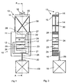
- the micro-gripper of Figures 1, 2 and 3 comprises a rigid frame 10 maintained in a fixed support (not shown). It is U-shaped and has two branches 11 parallel to its longitudinal axis AA. One of them presents, in its lower half, an internal indentation 12 of parallelepipedal shape, the function will be specified later.
- the frame 10 is coupled to two identical elastically deformable frames 13, also U-shaped, parallel to its plane and whose branches 14 extend his. These frames do not touch and have a thickness less than half that of the frame 10.
- the branches 14 have a thickness of the order of 1mm and a width of the order of 100 ⁇ m. This configuration gives them rigidity in the thickness of the frame and flexibility in his plan.
- the upper amount 15 of the two frames 13 is rigid and supports an interface attachment 16 of a jaw (not shown), slightly offset with respect to the axis AA. As the figures show, these frames are arranged head to tail, from so that the jaws attached to the interfaces 16 constitute a gripping member.
- the piston 17 comprises two rigid structures L 21 and 22 and two pairs of parallel blades elastically deformable 23 and 24.
- the wing 27 is parallel to the branches 11 of the frame 10 and along the branch opposite to that which comprises the notch 12. Note that the lower part of the wing 27 is in The wing 28, disposed at the top of the frame 10, is parallel to the wing 25 of the lower structure 21.
- the two rigid structures 21 and 22 are elastically coupled by the pair of blades 23, parallel to the bottom of the frame 10, which connects the wings 26 and 27.
- These blades have, typically, a thickness of about 100 ⁇ m and a width of the order from 2 to 3mm. This ratio of dimensions, visible by comparing FIGS. 1 and 3, gives the two boards stiffness in the direction of the thickness of the frame and the flexibility in his plan.
- One of the blades 23, at least, only intermediate elastic structure between the actuator 19 and the two frames 13 serves as a test body for a sensor of force 29 consisting, for example, of a strain gauge deposited on the blade in the form of a piezoelectric layer, the role of which will appear later.
- the frame 10 being fixed, the lateral rigidity of the blades 24 thus allows the piston 17 to remain in the axis of translation AA of the actuator.
- the two frames 13 are each coupled to the piston 17 via a elastically deformable return blade 30 which, for each frame, leaves, to approximately 45 °, from the end of the upper upright 15 furthest from the interface 16 to join the opposite end of the wing 28.
- the two blades 30 thus intersect more or less perpendicularly.
- these blades have a thickness of about 100 ⁇ m and a width of about 1mm. This report dimensions gives them great rigidity in the direction of the thickness of the frame and flexibility in his plan.
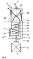
- Figure 2 shows that due to the resistance force exerted by the piece seized, the blades 23 are deformed. This deformation is measured by the sensor 29 which provides information to adjust the stroke of the piston 17 so as to obtain the most appropriate clamping force for the part being gripped.
- branches 14 and the blades 24 respectively guarantee the parallelism and the symmetry of the movement of the attachment interfaces 16 of the jaws.
- the micro-gripper which has just been described with reference to FIGS. 1, 2 and 3 is monolithic, advantageously made of silicon machined by electro-discharge (technique better known as electro-discharge mechaning, E.D.M.), only the decoupling rod 20 being an insert.
- FIG. 4 in which the elements common to FIGS. 1, 2 and 3 bear the same reference numbers, shows that the micro-gripper according to the invention can also be made in three flat parts assembled together, advantageously by gluing.
- the frame 10 is in two identical U-shaped parts 10a and 10b mounted head-to-tail and whose respective limbs 11a and 11b are extended by the flexible branches 14 of the two frames 13.
- the upper amounts 15 thereof are respectively connected to the piston 17 by the return blades 30.
- the piston 17 is then part of a U-shaped piece 31 forming a spacer, whose branches 32 are sandwiched between the branches 11a and 11b of the frame 10. It will be noted that the upper flange 28 of the piston 17 is coupled to the blades 30 by two studs 33a and 33b integral with the ends of these blades.
- the three parts constituting the micro-gripper of FIG. advantageously made, in one piece, of a copper alloy and beryllium or a spring steel.
- FIGS. variants can be applied to a monolithic micro-gripper or in three parts, as previously described.
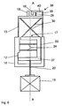
- the micro-gripper of FIG. 5 differs from that of FIGS. 1 to 3 essentially by the fact that the lower rigid structure 21 is suppressed, as well as, of course, the pair of resilient blades 23.
- the piston 34 is then reduced to the upper structure 22 whose wing 27 is elastically coupled to a branch 11 of the frame by the pair of blades 24.
- the wing 27 is secured, by its lower end, a shoe bar 35 parallel to the bottom of the frame 10, which is connected to the actuator 19 by a rod of 36 curved decoupling, in the center of which is fixed the sensor 29.
- This rod is elastically deformable in the plane of the frame and rigid in the direction of its thickness.
- the actuator 19 lifts the piston 34 via the rod of decoupling 36
- the deformation thereof is measured by the sensor 29 which, as for the first embodiment, provides information allowing to adjust the stroke of the piston so as to obtain the best clamping force appropriate to the coin seized.
- the micro-gripper of FIG. 6 differs from that of FIG. essentially by the fact that the shoe bar 35 is replaced by a simple bar 37 connected at its center, like the wing 25 of FIGS. 1 to 3, the actuator 19 by the straight decoupling rod 20.
- one of the attachment interfaces 16 ' is connected to the upper amount 15 of its frame 13 by a micro-structure 38 U-shaped connected to the amount 15 by its two branches 39. These are elastically deformable in the plane of the frame and receive the force sensor 29, while the transverse amount 40 of the microstructure 38 is rigid and terminates in the attachment interface 16 '.
- the branches 39 deform and the force sensor 29 can provide information relevant for setting the micro-gripper.
Landscapes
- Engineering & Computer Science (AREA)
- Robotics (AREA)
- Mechanical Engineering (AREA)
- Manipulator (AREA)
Description
- un bâti rigide en forme de U, qui possède deux branches parallèles à son axe et définissant entre elles un espace libre,
- deux cadres identiques parallèles en forme de U, qui possèdent chacun deux branches élastiquement déformables prolongeant les branches du bâti et dont le montant supérieur rigide supporte une interface de fixation d'un mors, décalée par rapport à l'axe, lesdits cadres étant disposés tête-bêche de manière à ce que les deux mors constituent un organe de préhension,
- un piston monté mobile en translation selon l'axe du bâti dans l'espace libre de celui-ci,
- des moyens d'accouplement dudit piston au montant supérieur de chaque cadre de manière à imposer à leurs branches respectives une déformation qui fait déplacer symétriquement les deux interfaces de fixation dans le plan du bâti perpendiculairement à son axe, et
- des moyens de commande du piston.
- Le piston comprend au moins une première structure rigide en L possédant deux ailes orthogonales, l'une étant disposée à la partie supérieure du bâti, l'autre étant parallèle à ses branches et couplée à l'une d'elles par une paire de lames élastiquement déformables.
- Le piston comprend une deuxième structure rigide en L orientée tête-bêche par rapport à la première et possédant deux ailes orthogonales, l'une étant disposée à la partie inférieure du bâti, l'autre étant parallèle à ses branches et couplée à l'aile de la première structure qui lui fait face par une paire de lames élastiquement déformables.
- Les moyens d'accouplement comportent deux lames de renvoi élastiquement déformables qui, pour chaque cadre, partent respectivement de l'extrémité du montant supérieur la plus éloignée de l'interface de fixation pour rejoindre l'extrémité opposée du piston.
- Les moyens de commande comportent un actionneur extérieur et une tige de découplage reliant l'actionneur à la portion du piston située dans la partie inférieure du bâti.
- Le micro-préhenseur comporte, en outre, un capteur de force disposé sur l'un de ses éléments élastiquement déformables pour fournir des informations sur la force exercée par les mors sur la pièce à saisir.
- Le capteur de force est disposé sur l'une des lames de la deuxième structure rigide en L.
- La tige de découplage est recourbée et élastiquement déformable ; dans ce cas le capteur de force est disposé sur elle.
- L'une des interfaces de fixation est reliée au montant supérieur de son cadre par une micro-structure élastiquement déformable ; dans ce cas, le capteur de force est disposé sur elle.
- Le micro-préhenseur est monolithique et réalisé en silicium usiné par électro-décharge (electro-discharge machining, E. D. M.).
- Le micro-préhenseur peut aussi être réalisé en trois pièces planes fixées entre elles, le bâti étant en deux parties identiques en U montées tête-bêche et dont les branches respectives sont prolongées par les branches souples des deux cadres, les montants supérieurs de ceux-ci étant respectivement liés au piston par les lames de renvoi et le piston faisant alors partie d'une pièce en U, formant entretoise, dont les branches sont insérées en sandwich entre les branches du bâti.
- Les lames de la deuxième structure rigide, les lames de renvoi, la tige de découplage recourbée et ladite micro-structure sont élastiquement déformables dans le plan du bâti et sont rigides dans le sens de son épaisseur.
- les figures 1 et 2 illustrent un micro-préhenseur selon un premier mode de réalisation particulier, les mors étant respectivement en position ouverte et fermée;
- la figure 3 est une vue d'un tel micro-préhenseur en position ouverte, représenté en coupe selon l'axe AA ;
- la figure 4 est une vue éclatée montrant, lorsqu'il n'est pas monobloc, les différentes pièces qui forment le micro-préhenseur des figures 1 à 3 ; enfin,
- les figures 5 et 6 représentent deux autres modes de réalisation d'un micro-préhenseur selon l'invention.
Claims (15)
- Micro-préhenseur caractérisé en ce qu'il comporte :un bâti rigide (10) en forme de U, qui possède deux branches (11) parallèles à son axe (AA) et définissant entre elles un espace libre (18),deux cadres identiques parallèles (13) en forme de U, qui possèdent chacun deux branches élastiquement déformables (14) prolongeant les branches (11) du bâti et dont le montant supérieur (15) rigide supporte une interface de fixation (16) d'un mors, décalée par rapport à l'axe (AA), lesdits cadres étant disposés tête-bêche de manière à ce que les deux mors constituent un organe de préhension,un piston (17) monté mobile en translation selon l'axe (AA) dans ledit espace libre (18),des moyens d'accouplement (30) dudit piston au montant supérieur (15) de chacun des deux cadres (13) de manière à faire subir à leurs branches (14) respectives une déformation qui fait déplacer symétriquement les deux interfaces de fixation (16) dans le plan du bâti (10) perpendiculairement à son axe AA, etdes moyens de commande (19, 20) dudit piston.
- Micro-préhenseur selon la revendication 1, caractérisé en ce que le piston(17) comprend au moins une première structure rigide en L (22), possédant deux ailes orthogonales (27, 28), l'une (28) étant disposée à la partie supérieure du bâti (10), l'autre (27) étant parallèle à ses branches (11) et couplée à l'une d'elles par une paire de lames élastiquement déformables (24) perpendiculaires auxdites branches.
- Micro-préhenseur selon la revendication 2, caractérisé en ce que le piston (17) comprend une deuxième structure rigide en L (21), orientée tête-bêche par rapport à la première (22) et possédant deux ailes orthogonales, l'une (25) étant disposée à la partie inférieure du bâti (10), l'autre (26) étant parallèle à ses branches (11) et couplée à l'aile (27) de la première structure (22) qui lui fait face par une paire de lames (23) élastiquement déformables.
- Micro-préhenseur selon l'une des revendications 1 à 3, caractérisé en ce que lesdits moyens d'accouplement comportent deux lames de renvoi élastiquement déformables (30) qui, pour chaque cadre (13), partent respectivement de l'extrémité du montant supérieur (15) la plus éloignée de l'interface de fixation (16) pour rejoindre l'extrémité opposée du piston (17).
- Micro-préhenseur selon l'une des revendications 1 à 4, caractérisé en ce que lesdits moyens de commande comportent un actionneur (19) extérieur et une tige de découplage (20) reliant l'actionneur à la portion du piston (17) située dans la partie inférieure du bâti (10).
- Micro-préhenseur selon l'une des revendications 1 à 5, caractérisé en ce qu'il comporte, en outre, un capteur de force (29) disposé sur l'un de ses éléments élastiquement déformables pour fournir des informations sur la force exercée par les mors sur la pièce à saisir.
- Micro-préhenseur selon les revendications 3 et 6, caractérisé en ce que ledit capteur de force (29) est disposé sur l'une des lames (23) de la deuxième structure rigide en L (22).
- Micro-préhenseur selon les revendications 5 et 6, caractérisé en ce que ladite tige de découplage (20) est recourbée et élastiquement déformable et en ce que ledit capteur de force (29) est disposé sur elle.
- Micro-préhenseur selon la revendication 6, caractérisé en ce que l'une des interfaces de fixation (16') est reliée au montant supérieur (15) de son cadre (13) par une micro-structure (38) élastiquement déformable et en ce que ledit capteur de force (29) est disposé sur elle.
- Micro-préhenseur selon l'une des revendications 1 à 9, caractérisé en ce qu'il est monolithique et réalisé en silicium usiné par électro-décharge.
- Micro-préhenseur selon l'une des revendications 1 à 9, caractérisé en ce qu'il est réalisé en trois pièces planes fixées entre elles, le bâti (10) étant en deux parties identiques en U (10a) et (10b) montées tête-bêche et dont les branches respectives (11a) et (11b) sont prolongées par les branches souples (14) des deux cadres (13), les montants supérieurs (15) de ceux-ci étant respectivement liés au piston (17) par les lames de renvoi (30) et le piston (17) faisant alors partie d'une pièce en U (31) formant entretoise, dont les branches (32) sont insérées en sandwich entre les branches (11a) et (11b) du bâti (10).
- Micro-préhenseur selon la revendication 1, caractérisé en ce que les branches (14) des cadres (13) sont élastiquement déformables dans le plan du bâti (10) et rigides dans le sens de son épaisseur, de manière à garantir le parallélisme du mouvement des interfaces de fixation (16).
- Micro-préhenseur selon la revendication 2, caractérisé en ce que l les lames (24) de la première structure rigide (22) sont élastiquement déformables dans le plan du bâti (10) et rigides dans le sens de son épaisseur, de manière à garantir la symétrie du mouvement des interfaces de fixation (16).
- Micro-préhenseur selon l'une des revendications 3, 4, 8 et 9, caractérisé en ce que respectivement les lames (23) de la deuxième structure rigide (21), lesdites lames de renvoi (30), la tige de découplage recourbée (36) et ladite micro-structure (38) sont élastiquement déformables dans le plan du bâti (10) et sont rigides dans le sens de son épaisseur.
- Micro-préhenseur selon la revendication 5, caractérisé en ce que ladite tige rectiligne (20) est rigide selon l'axe (AA) et souple dans les autres directions.
Priority Applications (2)
| Application Number | Priority Date | Filing Date | Title |
|---|---|---|---|
| DE2002605924 DE60205924T2 (de) | 2002-12-24 | 2002-12-24 | Mikrogreifer |
| EP02406141A EP1433575B1 (fr) | 2002-12-24 | 2002-12-24 | Micro-prehenseur |
Applications Claiming Priority (1)
| Application Number | Priority Date | Filing Date | Title |
|---|---|---|---|
| EP02406141A EP1433575B1 (fr) | 2002-12-24 | 2002-12-24 | Micro-prehenseur |
Publications (2)
| Publication Number | Publication Date |
|---|---|
| EP1433575A1 EP1433575A1 (fr) | 2004-06-30 |
| EP1433575B1 true EP1433575B1 (fr) | 2005-08-31 |
Family
ID=32405830
Family Applications (1)
| Application Number | Title | Priority Date | Filing Date |
|---|---|---|---|
| EP02406141A Expired - Lifetime EP1433575B1 (fr) | 2002-12-24 | 2002-12-24 | Micro-prehenseur |
Country Status (2)
| Country | Link |
|---|---|
| EP (1) | EP1433575B1 (fr) |
| DE (1) | DE60205924T2 (fr) |
Families Citing this family (5)
| Publication number | Priority date | Publication date | Assignee | Title |
|---|---|---|---|---|
| EP1914194A1 (fr) * | 2006-10-18 | 2008-04-23 | Paul Scherrer Institut PSI | Dispositif pour convertir un premier mouvement en un second mouvement avec un facteur de réduction |
| EP3885844A1 (fr) * | 2020-03-27 | 2021-09-29 | Nivarox-FAR S.A. | Pince pour machine reglante d'horlogerie |
| CN116871874B (zh) * | 2023-07-03 | 2026-01-23 | 联宝(合肥)电子科技有限公司 | 一种弹性居中对位装置 |
| EP4597070A1 (fr) | 2024-02-02 | 2025-08-06 | mimiX Biotherapeutics SA | Dispositif et procédé de génération de fragments de microtissu |
| CN119017429B (zh) * | 2024-08-26 | 2025-09-19 | 哈尔滨工业大学 | 一种小型两自由度压电精细操控器及实现对物体的夹持和旋转方法 |
Citations (1)
| Publication number | Priority date | Publication date | Assignee | Title |
|---|---|---|---|---|
| DE19644502A1 (de) * | 1996-10-25 | 1998-05-07 | Fraunhofer Ges Forschung | Greifervorrichtung für die Mikromontage kleiner Werkstücke mit wenigstens zwei Greiferelementen |
Family Cites Families (3)
| Publication number | Priority date | Publication date | Assignee | Title |
|---|---|---|---|---|
| JPH05293778A (ja) * | 1992-04-17 | 1993-11-09 | Seiko Instr Inc | マイクログリッパ |
| DE10107402A1 (de) * | 2001-02-14 | 2002-08-29 | Ruben Keoschkerjan | Piezoelektrischer paralleler Mikrogreifer |
| DE10114551C1 (de) * | 2001-03-24 | 2002-10-02 | Karlsruhe Forschzent | Mikrogreifer |
-
2002
- 2002-12-24 DE DE2002605924 patent/DE60205924T2/de not_active Expired - Fee Related
- 2002-12-24 EP EP02406141A patent/EP1433575B1/fr not_active Expired - Lifetime
Patent Citations (1)
| Publication number | Priority date | Publication date | Assignee | Title |
|---|---|---|---|---|
| DE19644502A1 (de) * | 1996-10-25 | 1998-05-07 | Fraunhofer Ges Forschung | Greifervorrichtung für die Mikromontage kleiner Werkstücke mit wenigstens zwei Greiferelementen |
Also Published As
| Publication number | Publication date |
|---|---|
| DE60205924D1 (de) | 2005-10-06 |
| DE60205924T2 (de) | 2006-06-14 |
| EP1433575A1 (fr) | 2004-06-30 |
Similar Documents
| Publication | Publication Date | Title |
|---|---|---|
| EP2164685B1 (fr) | Pince pour robot manipulateur a precision de serrage amelioree et robot manipulateur comportant au moins une telle pince | |
| EP0551045B1 (fr) | Dispositif de contrÔle de dimensions d'un objet, en particulier de diamètres extérieurs ou intérieurs de pièces mécaniques | |
| EP2476502B1 (fr) | Pince à enserrer des tôles, utilisée en association avec un bras manipulateur, et à module d'équilibrage déporté | |
| EP2718066B1 (fr) | Outil pour pince microtechnique | |
| FR2983844A1 (fr) | Liaison mecanique formant pivot pour structures mecaniques mems et nems | |
| EP0143673A1 (fr) | Préhenseur à patins de contact multiples | |
| EP0218546A1 (fr) | Dispositif de micropositionnement | |
| CA2660888C (fr) | Gamme de pinces a enserrer des toles a batis semblables, et de preference identiques, et pince d'une telle gamme | |
| EP1433575A1 (fr) | Micro-prehenseur | |
| EP3164690B1 (fr) | Dispositif de test mecanique en flexion pure et procede de mise en oeuvre | |
| EP1721134A1 (fr) | Capteur de poids | |
| EP1425129A1 (fr) | Pince-robot d'assemblage a dispositif de detalonnage et d'equilibrage auto-adaptatif | |
| FR2527968A1 (fr) | Poignet souple sensitif pour organe de manipulation | |
| EP4338290B1 (fr) | Dispositif de commande | |
| EP4186785A1 (fr) | Pilier flexible pour une ossature flexible d'une gouverne à géométrie variable | |
| EP3670439B1 (fr) | Articulation pour systemes micro et nanoelectromecaniques a deplacement hors-plan offrant une non-linearite reduite | |
| FR2579327A1 (fr) | Dispositif perfectionne d'essais de traction biaxiale | |
| EP0085605B1 (fr) | Dispositif de préhension à mesure d'effort à structure articulée possédant plusieurs degrés de liberté intercalée entre la plaque et son support | |
| EP1082596B1 (fr) | Outillage de montage sur une machine de test de traction de deux elements colles l'un a l'autre | |
| EP3498661B1 (fr) | Dispositif microelectromecanique et/ou nanoelectromecanique offrant une robustesse augmentee | |
| EP0895830A2 (fr) | Moyens de serrage à piston pour pousser ou tirer | |
| EP4058254B1 (fr) | Dispositif pour microactionneur et microactionneur equipe d'un tel dispositif | |
| EP0592341B1 (fr) | Perfectionnements aux poignées de porte à palettes basculantes | |
| EP4252976A1 (fr) | Pince de prehension de type parallele avec mise en reference d'un des deux mors | |
| EP3670932A1 (fr) | Dispositif d'assemblage de type verrou par mecanisme de coins bidirectionnel |
Legal Events
| Date | Code | Title | Description |
|---|---|---|---|
| PUAI | Public reference made under article 153(3) epc to a published international application that has entered the european phase |
Free format text: ORIGINAL CODE: 0009012 |
|
| AK | Designated contracting states |
Kind code of ref document: A1 Designated state(s): AT BE BG CH CY CZ DE DK EE ES FI FR GB GR IE IT LI LU MC NL PT SE SI SK TR |
|
| AX | Request for extension of the european patent |
Extension state: AL LT LV MK RO |
|
| 17P | Request for examination filed |
Effective date: 20041117 |
|
| GRAP | Despatch of communication of intention to grant a patent |
Free format text: ORIGINAL CODE: EPIDOSNIGR1 |
|
| AKX | Designation fees paid |
Designated state(s): CH DE FR GB LI |
|
| GRAS | Grant fee paid |
Free format text: ORIGINAL CODE: EPIDOSNIGR3 |
|
| GRAA | (expected) grant |
Free format text: ORIGINAL CODE: 0009210 |
|
| AK | Designated contracting states |
Kind code of ref document: B1 Designated state(s): CH DE FR GB LI |
|
| REG | Reference to a national code |
Ref country code: CH Ref legal event code: EP Ref country code: GB Ref legal event code: FG4D Free format text: NOT ENGLISH |
|
| REF | Corresponds to: |
Ref document number: 60205924 Country of ref document: DE Date of ref document: 20051006 Kind code of ref document: P |
|
| REG | Reference to a national code |
Ref country code: CH Ref legal event code: NV Representative=s name: GLN GRESSET & LAESSER NEUCHATEL CABINET DE CONSEIL |
|
| GBT | Gb: translation of ep patent filed (gb section 77(6)(a)/1977) |
Effective date: 20051129 |
|
| PLBE | No opposition filed within time limit |
Free format text: ORIGINAL CODE: 0009261 |
|
| STAA | Information on the status of an ep patent application or granted ep patent |
Free format text: STATUS: NO OPPOSITION FILED WITHIN TIME LIMIT |
|
| 26N | No opposition filed |
Effective date: 20060601 |
|
| PGFP | Annual fee paid to national office [announced via postgrant information from national office to epo] |
Ref country code: FR Payment date: 20061220 Year of fee payment: 5 |
|
| PGFP | Annual fee paid to national office [announced via postgrant information from national office to epo] |
Ref country code: GB Payment date: 20061222 Year of fee payment: 5 |
|
| PGFP | Annual fee paid to national office [announced via postgrant information from national office to epo] |
Ref country code: CH Payment date: 20071228 Year of fee payment: 6 |
|
| PGFP | Annual fee paid to national office [announced via postgrant information from national office to epo] |
Ref country code: DE Payment date: 20080131 Year of fee payment: 6 |
|
| GBPC | Gb: european patent ceased through non-payment of renewal fee |
Effective date: 20071224 |
|
| REG | Reference to a national code |
Ref country code: FR Ref legal event code: ST Effective date: 20081020 |
|
| PG25 | Lapsed in a contracting state [announced via postgrant information from national office to epo] |
Ref country code: GB Free format text: LAPSE BECAUSE OF NON-PAYMENT OF DUE FEES Effective date: 20071224 |
|
| PG25 | Lapsed in a contracting state [announced via postgrant information from national office to epo] |
Ref country code: FR Free format text: LAPSE BECAUSE OF NON-PAYMENT OF DUE FEES Effective date: 20071231 |
|
| REG | Reference to a national code |
Ref country code: CH Ref legal event code: PL |
|
| PG25 | Lapsed in a contracting state [announced via postgrant information from national office to epo] |
Ref country code: CH Free format text: LAPSE BECAUSE OF NON-PAYMENT OF DUE FEES Effective date: 20081231 Ref country code: LI Free format text: LAPSE BECAUSE OF NON-PAYMENT OF DUE FEES Effective date: 20081231 Ref country code: DE Free format text: LAPSE BECAUSE OF NON-PAYMENT OF DUE FEES Effective date: 20090701 |