EP1433305B1 - Procede de marquage spatial a modulation asymetrique robuste a un sur-echantillonnage spatial - Google Patents
Procede de marquage spatial a modulation asymetrique robuste a un sur-echantillonnage spatial Download PDFInfo
- Publication number
- EP1433305B1 EP1433305B1 EP03797490A EP03797490A EP1433305B1 EP 1433305 B1 EP1433305 B1 EP 1433305B1 EP 03797490 A EP03797490 A EP 03797490A EP 03797490 A EP03797490 A EP 03797490A EP 1433305 B1 EP1433305 B1 EP 1433305B1
- Authority
- EP
- European Patent Office
- Prior art keywords
- spatial
- spatial marking
- marking
- resolution
- points
- Prior art date
- Legal status (The legal status is an assumption and is not a legal conclusion. Google has not performed a legal analysis and makes no representation as to the accuracy of the status listed.)
- Expired - Lifetime
Links
Images

Classifications
-
- H—ELECTRICITY
- H04—ELECTRIC COMMUNICATION TECHNIQUE
- H04N—PICTORIAL COMMUNICATION, e.g. TELEVISION
- H04N1/00—Scanning, transmission or reproduction of documents or the like, e.g. facsimile transmission; Details thereof
- H04N1/32—Circuits or arrangements for control or supervision between transmitter and receiver or between image input and image output device, e.g. between a still-image camera and its memory or between a still-image camera and a printer device
- H04N1/32101—Display, printing, storage or transmission of additional information, e.g. ID code, date and time or title
- H04N1/32144—Display, printing, storage or transmission of additional information, e.g. ID code, date and time or title embedded in the image data, i.e. enclosed or integrated in the image, e.g. watermark, super-imposed logo or stamp
- H04N1/32149—Methods relating to embedding, encoding, decoding, detection or retrieval operations
- H04N1/32203—Spatial or amplitude domain methods
- H04N1/32208—Spatial or amplitude domain methods involving changing the magnitude of selected pixels, e.g. overlay of information or super-imposition
-
- H—ELECTRICITY
- H04—ELECTRIC COMMUNICATION TECHNIQUE
- H04N—PICTORIAL COMMUNICATION, e.g. TELEVISION
- H04N1/00—Scanning, transmission or reproduction of documents or the like, e.g. facsimile transmission; Details thereof
- H04N1/32—Circuits or arrangements for control or supervision between transmitter and receiver or between image input and image output device, e.g. between a still-image camera and its memory or between a still-image camera and a printer device
- H04N1/32101—Display, printing, storage or transmission of additional information, e.g. ID code, date and time or title
- H04N1/32144—Display, printing, storage or transmission of additional information, e.g. ID code, date and time or title embedded in the image data, i.e. enclosed or integrated in the image, e.g. watermark, super-imposed logo or stamp
- H04N1/32149—Methods relating to embedding, encoding, decoding, detection or retrieval operations
- H04N1/32309—Methods relating to embedding, encoding, decoding, detection or retrieval operations in colour image data
-
- H—ELECTRICITY
- H04—ELECTRIC COMMUNICATION TECHNIQUE
- H04N—PICTORIAL COMMUNICATION, e.g. TELEVISION
- H04N2201/00—Indexing scheme relating to scanning, transmission or reproduction of documents or the like, and to details thereof
- H04N2201/32—Circuits or arrangements for control or supervision between transmitter and receiver or between image input and image output device, e.g. between a still-image camera and its memory or between a still-image camera and a printer device
- H04N2201/3201—Display, printing, storage or transmission of additional information, e.g. ID code, date and time or title
- H04N2201/3269—Display, printing, storage or transmission of additional information, e.g. ID code, date and time or title of machine readable codes or marks, e.g. bar codes or glyphs
- H04N2201/327—Display, printing, storage or transmission of additional information, e.g. ID code, date and time or title of machine readable codes or marks, e.g. bar codes or glyphs which are undetectable to the naked eye, e.g. embedded codes
-
- Y—GENERAL TAGGING OF NEW TECHNOLOGICAL DEVELOPMENTS; GENERAL TAGGING OF CROSS-SECTIONAL TECHNOLOGIES SPANNING OVER SEVERAL SECTIONS OF THE IPC; TECHNICAL SUBJECTS COVERED BY FORMER USPC CROSS-REFERENCE ART COLLECTIONS [XRACs] AND DIGESTS
- Y10—TECHNICAL SUBJECTS COVERED BY FORMER USPC
- Y10S—TECHNICAL SUBJECTS COVERED BY FORMER USPC CROSS-REFERENCE ART COLLECTIONS [XRACs] AND DIGESTS
- Y10S283/00—Printed matter
- Y10S283/902—Anti-photocopy
Definitions
- the general field concerns a technique of signal processing and image making it possible to camouflage information invisibly in digital (image, video, sound) or analog (print) media.
- An asymmetrically modulated digital spatial tagging is an extension of conventional digital watermarks. This extension allows in particular to cover the printed media by offering a solution to invisibly print a digital spatial marking on a uniform color media with a visible color ink.
- the field of application concerns the securing of printed documents and packaging against counterfeiting and falsification.
- Special ink prints use the particular chemical properties of the ink to provide a definite response to a particular action.
- fluorescent inks become very bright when illuminated by a particular wavelength, some inks are even invisible to natural light, other inks change color depending on their orientation or temperature (and may reveal by warming the paper with a finger), etc.
- Special inks have the common point of being particularly expensive and requiring changes in the usual industrial production chain (additional mask for offset, for example).
- additional mask for offset for example.
- Codes using invisible inks unlike the two previous groups, hide digital information. These codes can be characters, barcodes, 2D codes, etc. In addition to its high cost and inherent to invisible inks, this system has two major drawbacks. On the one hand, because of the nature of the codes used, it is located on a certain part of the document or the packaging and it is therefore possible to destroy it without altering the entire surface. On the other hand, the codes used always have geometric peculiarities (bars, geometric figures, characters, etc.) clearly identifying them as anti-copy devices. This greatly facilitates the task of the pirate seeking to reveal and reproduce the ink. Moreover as soon as the pirate knows how to realize this reproduction, ipso facto holds the means of reproducing the code.
- the digital watermark technique also known as digital tattooing, is a technique for hiding information in a robust and imperceptible manner in multimedia data such as video, images, documents, etc.
- the information that is hidden is called the signature.
- This signature can be for example a number, a name or even an image.
- the document EP 0 789 480 describes how to insert a microstructure into a document, essentially to avoid unauthorized copying. This structure is invisible to the eye but recognizable by a suitable reader.
- the present invention describes a method for overcoming this constraint and thus allowing the use of a low resolution scanner (or any other optical acquisition method) to detect a high resolution printed spatial marking.
- a low resolution scanner or any other optical acquisition method
- it makes it possible, for example, to print a spatial marking at 600 dpi (resolution compatible with industrial printers) and to detect it at 200 dpi (resolution compatible with industrial scanners).
- Spatial marking is a cloud of points with pseudo-random spatial distribution.
- the print resolution on the basis of the effective size of the spatial marking once printed in relation to its size in pixels, and not as the maximum resolution of points per unit length that can provide 'printer.
- the size of the points has a diameter of the order of 1 / d .
- a digitization of these points can be accomplished with a scanner having a resolution d : the size of the printed dots being identical to the resolution of the digitizer, it is possible to discriminate them (the bottom point is to the right of the point of the top). In the case of digitization performed at a lower resolution (for example twice lower), such discrimination is theoretically impossible. In this case, we see that the digitizer digitizes the two points as belonging to the same line. There is no discrimination of the two points and the scanner considers that there is in fact only one point.
- one solution is to space the points so as to compensate exactly the difference in resolution between printing and scanning.
- additional empty lines have been inserted allowing vertical spacing of the points of 2 / d .
- the notable advantage of this invention is that it can detect spatial tagging with the many systems based on low resolution digital scanners. This is particularly the case for high-speed digitizers used for paper documents (checks, bank transfers, etc.) but also for certain card readers.
- the ratio between the print resolution and the reading resolution is typically between 2 and 5.
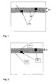
- the Figure 1 illustrates a scanner band with a resolution lower than the PC point resolution applied on this LN band.
- the scanner is active on a 2 / d resolution LN band that is less than half the 1 / d print resolution.
- the scanner is of resolution 1 / d equivalent to the resolution of the printing.
- the reading of the first line LN1 and the second line LN2 makes it possible to detect without problem the PC points of this spatial marking.
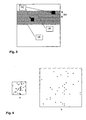
- the figure 3 illustrates a printed spatial marking with a resolution 1 / d (the resolution of PC points).
- the size of the PC point is half the bandwidth 2 / d of acquisition of a scanner.
- the figure 4 illustrates the print result of a spatial mark, the figure 4a being the basic spatial tagging and the figure 4b being the printed spatial marking.
- the two spatial markings have a number of identical points. This example is based on a scan resolution report of the scanner of 3. It can be seen that the area used by the basic spatial marking 4a is 3 times smaller than the spatial marking 4b printed. At the same time, each printed dot is spaced at least 2 unprinted points.
- One embodiment of the invention is based on a post-processing method of a spatial marking image illustrated by the diagram of the Figure 5 .
- a pseudo-randomly distributed standard spatial marking of size X ⁇ Y is first generated.
- the latter is then oversampled in a binary manner by a factor n in its horizontal and vertical dimensions by a first module ST1.
- the result is a spatial marking CR of size NX x NY , in particular the points encoding the signal - carriers of the redundant information - now have a size of N ⁇ N.
- This image is then reprocessed by means of an erosive filter ST2 leading to points again of a size of 1x1 but in an image still making NX x NY . This process is referred to as "erosive oversampling".
- the spatial marking CR ' (NX x NY) is first printed with a resolution d1.
- the printed medium thus obtained is subsequently digitized in the SCN module with a resolution d2 .
- the object of the present invention is precisely that d2 ⁇ d1 .
- the method described above can be generalized to the cases of anisotropic treatment of spatial tagging.
- the resolutions used for scanning and printing are different in the x and y directions.
- This method acts independently on each of these dimensions, it can be applied directly.
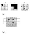
- the figure 7 illustrates the process for preparing a spatial marking according to the invention.
- the figure 7a shows the basic spatial marking at a resolution d
- the first step is the oversampling step according to the resolution on a scanner.
- the resolution in x is four times ( n ) lower and the resolution in there is three times ( m ) lower than that of the printing.
- the Figure 7c illustrates an alternative that consists in choosing only one of the points according to its position.
- the point retained is that at the bottom left.
- the resulting spatial marking necessarily includes spaced points so that only one point is taken during an acquisition at the maximum resolution of the scanner.
- each acquisition zone does not necessarily correspond with the spatial marking division during printing.
- An acquisition area is illustrated by a dotted line. It is noted that for a given area, there remains only one spatial marking point which allows an effective treatment.
- Designing spatial tagging is about figuring out which points need to be printed and which ones should show the bottom of the document. This design takes into account the method used for decoding.
- the decoding of the spatial marking requires the use of its autocorrelation, intercorrelation and statistical correlation properties with the encoded data respectively to compensate for the affine geometric transformations, the translations and the eventual noise of the signal.
- the autocorrelation and correlation properties are defined during the spatial marking design and must take into account the desired sub-sampling level.
- the points encode binary information according to a spectrum display method and these points are also chosen so that the image obtained has autocorrelation properties (see, for example M. Kutter, F. Jordan, F. Bossen, "Digital watermaking of color images using amplitude modulation," Journal of Electronic Imaging, Vol. 7, No. 2, pp. 326-332, April 1998 ).
- the following paragraphs describe an embodiment of a method of designing spatial marking correlated with binary information and autocorrelated spatial marking.
- i ⁇ - 1,1 ⁇ be the value of a bit to encode.
- ⁇ x, y ⁇ be a set of pseudo randomly chosen points (on the basis of a key) among all the points of the image X x Y and k an index identifying each of the coordinates ⁇ x, y ⁇ of these points.
- a (k) be a pseudo-random generator defined by a second key and giving values ⁇ -1,1 ⁇ .
- v be a color between 0 (black / color) and 1 (white).
- One method consists in carrying out the translation using a modulo on the size of the image.
- any method of obtaining a distinguishable point with respect to a background may be used.
- laser engraving of dots on a glass surface can be cited to hide an invisible code. It is also possible to use points with magnetic features different from those of the background.
- the present invention can be directly generalized to the detection of non-optical properties of the points (electrical, magnetic, position in depth / height).
- the digital acquisition process of the spatial marking of a surface can also be completely dissociated from the digital processing process making it possible to detect this marking. For example, it is possible to digitally photograph a marked surface and send the image by network to a remote computer that performs the detection. The result of this detection can also be returned to the operator.
- the development of mobile phones with low resolution camera makes the process of the invention very attractive.
Landscapes
- Engineering & Computer Science (AREA)
- Multimedia (AREA)
- Signal Processing (AREA)
- Editing Of Facsimile Originals (AREA)
- Image Processing (AREA)
- Holo Graphy (AREA)
- Laser Beam Processing (AREA)
- Analogue/Digital Conversion (AREA)
- Manufacturing Optical Record Carriers (AREA)
- Optical Communication System (AREA)
- Facsimile Scanning Arrangements (AREA)
- Complex Calculations (AREA)
- Laser Beam Printer (AREA)
- Inspection Of Paper Currency And Valuable Securities (AREA)
Description
- Le domaine général concerne une technique de traitement du signal et d'image permettant de camoufler des informations de manière invisible dans des médias digitaux (image, vidéo, son) ou analogiques (imprimé).
- Un marquage spatial numérique à modulation asymétrique est une extension des filigranes numériques classiques. Cette extension permet en particulier de couvrir les médias imprimés en offrant une solution pour imprimer de manière invisible un marquage spatial numérique sur un média de couleur uniforme avec une encre de couleur visible. Le domaine d'application concerne la sécurisation des documents et emballages imprimés contre la contrefaçon et la falsification.
- Les systèmes usuels destinés à prévenir la contrefaçon ou l'altération de documents imprimés ou gravés peuvent être classés en différents groupes:
- • les hologrammes, les impressions de motifs spéciaux
- • les impressions avec encres spéciales ou code à encres invisibles
- • les systèmes à puce ou antennes
- Les hologrammes, motifs spéciaux et autres décorations sont difficiles à reproduire car leur réalisation nécessite un équipement spécial. Ils sont spécialement conçus pour interférer avec les systèmes de photocopie classique de telle sorte que la copie soit visiblement différente de l'original. Ces systèmes peuvent être contrôlés visuellement sans l'aide de dispositifs particuliers mais présentent l'inconvénient d'être coûteux, assez connus pour être reproduits sans problèmes par des experts en contrefaçon, et finalement leur visibilité nuit à l'esthétique de l'objet protégé (emballage de parfum par exemple). Leur visibilité est également la raison de leur efficacité limitée dans la mesure où un pirate peut facilement identifier l'élément de sécurité, soit pour le copier, soit pour l'effacer physiquement.
- Les impressions avec encres spéciales utilisent des propriétés chimiques particulières de l'encre pour fournir une réaction déterminée à une action particulière. Ainsi, les encres fluorescentes deviennent très lumineuses quand elles sont éclairées par une longueur d'onde particulière, certaines encres sont même invisibles à la lumière naturelle, d'autres encres changent de couleur en fonction de leur orientation ou de leur température (et peuvent se révéler en chauffant le papier avec un doigt), etc. Les encres spéciales ont comme point commun d'être particulièrement coûteuses et de nécessiter d'opérer des modifications dans la chaîne de production industrielle habituelle (masque supplémentaire pour l'offset par exemple). De plus, bien que plus robuste à la contrefaçon que le groupe précédent, il est également possible de reproduire leurs effets dans la mesure où le pirate peut contrôler par lui-même la fidélité de sa copie par rapport à l'original dès qu'il dispose du dispositif faisant réagir l'encre.
- Les codes utilisant des encres invisibles, à la différence des deux groupes précédents, permettent de cacher une information numérique. Ces codes peuvent être des caractères, des codes barres, des codes 2D, etc. En plus de son coût élevé et propre aux encres invisibles, ce système a deux inconvénients majeurs. D'une part, du fait de la nature des codes utilisés, il est localisé sur une certaine partie du document ou de l'emballage et il est donc possible de le détruire sans altérer la totalité de la surface. D'autre part, les codes utilisés ont toujours des particularités géométriques (barres, figures géométriques, caractères, etc) les identifiant clairement comme des dispositifs anti-copie. Cela facilite grandement la tache du pirate cherchant à révéler et à reproduire l'encre. De plus dès que le pirate sait réaliser cette reproduction, il détient ipso facto le moyen de reproduire le code.
- Finalement les systèmes basés sur des mémoires ou processeurs embarqués cumulent les inconvénients d'être très coûteux, inesthétiques et localisés. Leur application principale consiste plus à sécuriser une communication, ou à stocker dynamiquement une information plutôt qu'à distinguer un original d'une copie.
- La technique du filigrane numérique, également connue sous le nom de tatouage numérique, est une technique permettant de cacher des informations de manière robuste et imperceptible dans des données multimédia telles que la musique, la vidéo, les images, les documents, etc. L'information qui est cachée s'appelle la signature. Cette signature peut être par exemple un numéro, un nom ou même une image. Après la protection des données multimédia avec un filigrane numérique on parle d'image signée, de vidéo signée, etc.
- De nombreuses publications ont été faites sur les différentes techniques permettant de cacher un filigrane dans une image, dans une vidéo ou un signal audio. En ce qui concerne les images, ces dernières peuvent se classer en fonction de la technique utilisée pour le marquage : certaines opèrent des modifications directement dans le domaine spatial (voir par exemple [1] M. Kutter, F. Jordan, F. Bossen, "Digital watermaking of color images using amplitude modulation", Journal of Electronic Imaging, vol. 7, n° 2, pp. 326-332, April 1998.), d'autres opèrent ces modifications dans un domaine transformé (par exemple le domaine fréquentiel) voire des domaines intermédiaires comme les ondelettes (voir [2] Shelby Pereira, Sviatoslav Voloshynovskiy and Thierry Pun, Optimized wavelet domain watermark embedding strategy using linear programming, In Harold H. Szu and Martin Vetterli eds., Wavelet Applications VII (part of SPIE AeroSense 2000), Orlando, Florida USA, April 26-28 2000.).
- Le procédé décrit dans le brevet numéro
WO0225599 CH20000001832 20000920 - Le document
EP 0 789 480 décrit comment insérer une microstructure dans un document, essentiellement afin d'éviter une copie non autorisée. Cette structure est invisible à l'oeil mais reconnaissable par un lecteur approprié. - La présente invention décrit un procédé permettant de s'affranchir de cette contrainte et permettant donc d'utiliser un scanner basse résolution (ou toute autre méthode d'acquisition optique) pour détecter un marquage spatial imprimé à haute résolution. Ainsi, elle permet par exemple d'imprimer un marquage spatial à 600 dpi (résolution compatible avec les imprimantes industrielles) et de le détecter à 200 dpi (résolution compatible avec les scanners industriels).
- Un marquage spatial se présente comme un nuage de points à répartition spatiale pseudo aléatoire. Dans ce qui suit on définit « la résolution d'impression » sur la base de la taille effective du marquage spatial une fois imprimé rapporté à sa taille en pixel, et non pas comme la résolution maximale de points par unité de longueur que peut fournir l'imprimante.
- Par exemple, considérons un marquage spatial de 300 par 300 pixels, imprimé avec une imprimante de résolution 1200 dpi, Supposons que la taille obtenue après impression soit de 1 pouce par 1 pouce. Dans ce cas, on considèrera que la résolution effective d'impression est de 300 points par pouce (ou 300 dpi), et non de 1200 dpi.
- Afin d'illustrer le caractère critique des résolutions respectives d'impression et de numérisation, un exemple est donné dans ce qui suit pour le cas particulier de la détermination du positionnement vertical de deux points. Lorsque le marquage spatial est imprimé à une résolution de d points par unité de longueur, la taille des points a un diamètre de l'ordre de 1/d. Une numérisation de ces points peut être accomplie avec un scanner possédant une résolution d: la taille des points imprimés étant identiques à la résolution du numériseur, il est possible de les discriminer (le point du bas se situe à droite du point du haut). Dans le cas d'une numérisation réalisée à une résolution inférieure (par exemple deux fois inférieure), une telle discrimination est théoriquement impossible. Dans ce cas, on voit que le numériseur digitalise les deux points comme appartenant à la même ligne. Il n'y a pas de discrimination des deux points et le scanner considère qu'il n'y a en fait qu'un point.
- Le même raisonnement est également valide pour la résolution horizontale de l'image. Cette limitation semble donc être fondamentalement intrinsèque à la technologie du marquage spatial et il était jusqu'ici admis que le résolution de numérisation ne pouvait en aucun cas être inférieure à celle d'impression.
- Le procédé suivant montre néanmoins qu'une telle possibilité existe : une solution consiste à espacer les points de manière à compenser exactement la différence de résolution entre impression et numérisation. Dans ce cas, des lignes supplémentaires vides ont été insérées permettant un espacement vertical des points de 2/d.
- L'avantage notable de cette invention est qu'elle permet de détecter un marquage spatial avec les nombreux systèmes basés sur des scanners digitaux à basse résolution. C'est le cas en particulier des numériseurs à haut débit utilisés pour les documents papier (chèques, virements bancaires, etc.) mais aussi de certains lecteurs de carte.
- Le rapport entre la résolution d'impression et la résolution de lecture est typiquement comprise entre 2 et 5.
- Un autre avantage du système est qu'il permet d'augmenter l'invisibilité du marquage spatial en utilisant les deux phénomènes suivants :
- • Diminution de la taille des points
- • Diminution de la concentration de points par unité de surface imprimée Ces paramètres sont mathématiquement quantifiés ci-dessous.
-
-
Figure 1 : Représentation du signal et de la zone numérisée par un scanner d'une résolution deux fois plus basse que la taille des points. -
Figure 2 : Représentation du signal et de la zone numérisée par un scanner de résolution identique à la taille des points. -
Figure 3 : Utilisation d'une résolution de numérisation plus basse que celle d'impression. -
Figure 4 : Illustration du changement de l'espacement pour la dimension verticale et horizontale. -
Figure 5 : Diagramme du procédé permettant d'obtenir un marquage spatial sur échantillonné et érodé. -
Figure 6 : Diagramme de la mise en oeuvre du marquage spatial modifié pour l'impression et la détection. -
Figure 7 : Illustration de la fonction de sur échantillonnage et érosion -
Figure 8 : Représentation de l'acquisition par un scanner d'un marquage spatial -
Figure 9 : Illustration d'un marquage spatial auto-correlé - La
Figure 1 illustre une bande de scanner d'une résolution inférieure à la résolution des points PC appliqué sur cette bande LN. Le scanner est actif sur une bande LN de résolution 2/d soit de moitié inférieure à la résolution d'impression 1/d. - Sur la
Figure 2 , le scanner est de résolution 1/d équivalente à la résolution de l'impression. La lecture de la première ligne LN1 et la seconde ligne LN2 permet de détecter sans problème les points PC de ce marquage spatial. - La
figure 3 illustre un marquage spatial imprimé avec une résolution 1/d (la résolution des points PC). La taille du point PC est de moitié inférieure à la largeur de bande 2/d d'acquisition d'un scanner. - La
figure 4 illustre le résultat d'impression d'un marquage spatial, lafigure 4a étant le marquage spatial de base et lafigure 4b étant le marquage spatial imprimé. Les deux marquage spatial ont un nombre de points identiques. Cet exemple est basé sur un rapport d'impression sur résolution du scanner de 3. On constate que la surface utilisée par le marquage spatial de base 4a est de taille 3 fois inférieure au marquage spatial 4b imprimé. Parallèlement, chaque point imprimé est espacé au minimum de 2 points non imprimé. - Une méthode de réalisation de l'invention est basée sur un procédé de post traitement d'une image de marquage spatial illustré par le diagramme de la
Figure 5 . Un marquage spatial standard à répartition pseudo aléatoire d'une taille X×Y est d'abord généré. Ce dernier est ensuite sur-échantillonné de manière binaire d'un facteur n dans ses dimensions horizontales et verticales par un premier module ST1. Le résultat est un marquage spatial CR de taille NX x NY dont en particulier les points encodant le signal - porteurs de l'information redondante - font désormais une taille de N×N. Cette image est ensuite retraitée au moyen d'un filtre érosif ST2 conduisant à des points à nouveau d'une taille de 1x1 mais dans une image faisant toujours NX x NY. Ce procédé est ainsi qualifié de « sur-échantillonnage érosif ». - La mise en oeuvre de l'impression et détection du marquage spatial ainsi obtenu est illustrée par la
Figure 6 . Dans une première étape PRT, le marquage spatial CR' (NX x NY) est tout d'abord imprimé avec une résolution d1. Le support imprimé ainsi obtenu est subséquemment numérisé dans le module SCN avec une résolution d2. - Comme mentionné précédemment, l'objet de la présente invention est précisément que d2< d1.
- Il existe une relation liant mathématiquement le procédé de post traitement à la mise en oeuvre du marquage spatial. Cette dernière est donné par :

- Par exemple un marquage spatial peut être imprimé avec une résolution de d1=300 dpi et scanné avec une résolution de d2=100 dpi. Dans ce cas, le rapport des résolutions est n=3, ce qui signifie que le nombre de points horizontaux et verticaux définissant le marquage spatial imprimé CR' est 3 fois supérieurs à celui obtenu après numérisation.
- La numérisation avec une résolution d2 du marquage spatial post traité conduit à une diminution du contraste entre les points numérisés et le fond qui dépend du rapport n. La couleur finale c' du point numérisé peut être calculée: soit b la couleur de fond et c la couleur des points du marquage spatial (tous deux compris entre 0 et 1). c' est alors calculée en tenant compte du fait qu'il y a un seul point de couleur c et n 2-1 points de couleur b:
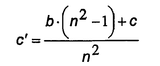
- Dans le cas particulier d'un signal noir c=0 sur fond blanc b=1, on peut constater que c' > c, et que cette couleur moyenne se rapproche de celle du fond (b=1), cela d'autant plus que n est grand. Le contraste du signal par rapport au fond est donc diminué, ce qui augmente l'invisibilité en même temps que le rapport signal bruit qui caractérise la clarté du marquage spatial par rapport au support sur lequel il est imprimé. Par exemple, pour n=3, un signal noir c=0 sur fond blanc b=1, la couleur du point numérisé sera c'=0.88. Cela correspond à une diminution du contraste avec la couleur de fond de 88% par rapport à la couleur initiale du point noir.
- La méthode décrite ci-dessus peut être généralisée aux cas d'un traitement anisotrope du marquage spatial. Dans ce cas, les résolutions utilisées pour la numérisation et l'impression sont différentes selon les directions x et y. Comme cette méthode agit indépendamment sur chacune de ces dimensions, elle peut être appliquée directement. Les relations se généralisent alors en considérant la résolution selon les directions x et y utilisées pour l'impression (resp. d1x et d1y) et celles utilisées pour la numérisation (resp. d2x et d2y) donnant le facteur de sur échantillonnage érosif selon les directions x et y, respectivement nx et ny :


- Ces facteurs sont en particulier applicables dans le cas d'imprimantes industrielles à jet d'encre dont la vitesse de défilement du papier est susceptible d'engendrer une résolution différente dans les deux dimensions, un effet similaire peut également être constaté sur un scanner.
- La
figure 7 illustre le procédé de préparation d'un marquage spatial selon l'invention. Lafigure 7a montre le marquage spatial de base à une résolution d La première étape est l'étape de sur échantillonnage en fonction de la résolution sur scanner. Selon l'exemple illustré à lafigure 7b , la résolution en x est quatre fois (n) inférieure et la résolution en y est trois fois (m) inférieure à celle de l'impression. - Pour illustrer le processus d'érosion, la
figure 7c illustre une alternative qui consiste à ne choisir que l'un des points selon sa position. Ainsi, selon cet exemple, le point retenu est celui en bas à gauche. Le marquage spatial résultant comprend nécessairement des points espacés de sorte que seulement un point soit pris lors d'une acquisition à la résolution maximale du scanner. - Le fonctionnement du scanner est illustré par la
figure 8 . Son fonctionnement est essentiellement asynchrone et chaque zone d'acquisition ne correspond pas forcément avec la division du marquage spatial lors de l'impression. Une zone d'acquisition est illustrée par une ligne pointillée. On constate que pour une zone donnée, il ne reste qu'un seul point de marquage spatial ce qui autorise un traitement efficace. - Concevoir le marquage spatial revient à déterminer quels sont les points qui doivent être imprimés et ceux qui doivent laisser apparaître le fond du document. Cette conception prend en compte la méthode utilisée pour le décodage.
- Le décodage du marquage spatial requiert l'utilisation de ses propriétés d'autocorrélation, d'intercorrélation et de corrélation statistiques avec les données encodées respectivement pour compenser les transformations géométriques affines, les translations et le bruit éventuel du signal. Les propriétés d'autocorrélation et de corrélation sont définies lors de la conception du marquage spatial et doivent prendre en compte le niveau de sous échantillonnage désiré. Au niveau théorique, les points encodent une information binaire selon un procédé d'étalage de spectre et ces points sont également choisis pour que l'image obtenue possède des propriétés d'autocorrélation (voir par exemple M. Kutter, F. Jordan, F. Bossen, "Digital watermaking of color images using amplitude modulation", Journal of Electronic Imaging, vol. 7, n° 2, pp. 326-332, April 1998). Les paragraphes ci-dessous décrivent un mode de réalisation d'une méthode de conception d'un marquage spatial corrélé à une information binaire et d'un marquage spatial autocorrélé.
- Soit i={-1,1} la valeur d'un bit à encoder. Soit {x,y} un ensemble de points choisis pseudo aléatoirement (sur la base d'une clé) parmi tous les points de l'image X x Y et k un index identifiant chacune des coordonnées {x,y} de ces points. Soit a(k) un générateur pseudo-aléatoire défini par une deuxième clé et donnant des valeurs {-1,1}. Soit v, une couleur comprise entre 0 (noir/couleur) et 1 (blanc). Soit c(k) la couleur finale du point k du marquage spatial. La formule suivante est alors appliquée :

- Par exemple, si un seul bit est codé avec k variant de 0 à 99, une couleur de marquage spatial v=0, et a(k) = k modulo 2, cela signifie que l'image du marquage spatial sera composée de 50 points noirs et 50 points blancs, tous les autres points du marquage spatial restant blancs. Ces points encoderont ce bit avec une redondance de 100.
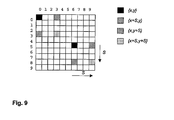
- Une méthode permettant d'obtenir un marquage spatial présentant une propriété d'autocorrélation consiste à concevoir l'image numérique du marquage spatial en dupliquant 4 fois l'ensemble des points {x,y}. Cette duplication peut être effectuée en translatant l'ensemble des points selon 4 vecteurs définis par (0,0), (0,S), (S,0), (S,S) où S défini la distance de translation. Il est possible de réaliser cette duplication en utilisant la méthode suivante:
- o Sélection d'un ensemble de points {x,y} telles que les coordonnées (x,y) sont paires
- o Sélection d'une distance de translation impaire S
- o Création du marquage spatial avec les 4 ensembles de points {x,y}, {x+S,y}, {x,y+S}, {x+S,y+S}
- Cette méthode garantie qu'aucun des points des 4 ensembles ne se juxtaposent. La
figure 9 illustre cette approche avec un ensemble {x,y} comprenant 2 points et une translation S=3. - Lors de cette opération, certains points sont susceptibles d'avoir des coordonnées supérieurs à la taille de l'image du marquage spatial X x Y. Une méthode consiste à effectuer la translation en utilisant un modulo sur la taille de l'image. Les formules suivantes illustrent la méthode du modulo pour la coordonnée horizontale x:


- Le même principe est appliqué à la coordonnée y.
- L'autocorrélation ainsi introduite est utilisée pour compenser une transformation géométrique de type affine éventuellement produite par l'acquisition numérique du marquage spatial. Soit x,y les coordonnées d'un point du cryptoglyph avant impression et x',y' les coordonnées de ce point après numérisation, la relation affine entre ces coordonnées s'écrit:


- Une fois les coefficients (a,b,c,d) déterminés à partir de la position de la figure d'autocorrélation, il est donc possible d'établir les coordonnées (x,y) originales en compensant la transformation géométrique induite par l'acquisition numérique.
- Dans le cas particulier de la présente invention, le décodage du signal est rendu difficile car le sous-échantillonage produit par la numérisation basse résolution entraîne une diminution du contraste entre les points et la couleur de fond, ce contraste diminuant de plus avec le carré de n. Deux solutions sont utilisées pour compenser cette diminution du rapport signal bruit:
- o Augmentation de la redondance du codage Pour une image de taille X x Y, la redondance du codage est définie par la formule suivante:

où la densité p, comprise entre 0 et 1, définie la proportion de points imprimés par rapport à la taille de l'image en pixels, et b défini le nombre de bits encodés. Ainsi si l'on considère l'image d'un marquage spatial de taille 100 par 100 pixels dont la densité est de 0.1 et encode 10 bits, on obtient une redondance de 100. - o Augmentation du contraste entre la couleur du point et le fond Pour cela il faut choisir une couleur d'encre c qui maximise la valeur absolue |c-b|.
- Ces deux solutions peuvent être utilisées séparément ou simultanément. Elles sont mises en oeuvre de manière empirique, sachant que:
- Au delà d'un certain seuil qui dépend entre autre de la couleur d'impression, du support d'impression et de la résolution d'impression, il n'est pas possible d'augmenter simultanément la densité et le contraste car le marquage spatial devient visible.
- La valeur de redondance ne peut pas descendre sous un certain seuil qui dépend des altérations que le support imprimé est susceptible de subir, faute de quoi des erreurs de décodage sont susceptibles de se produire.
- Les propriétés du marquage spatial définies précédemment permettent d'effectuer un décodage fiable qui se décompose selon les étapes suivantes
- acquisition numérique d'une image du support,
- filtrage sur l'image obtenue pour éliminer les parties ne comprenant pas le marquage spatial. Ce filtrage peut prendre compte les caractéristiques d'un graphisme éventuellement imprimé sur le support. Il peut être réalisé en utilisant une compensation basée sur une couleur uniforme ou par une prédiction des couleurs du support avant impression du graphisme. Une telle prédiction peut être réalisée par un filtre de débruitage (de type Wiener par exemple).
- utilisation des propriétés d'autocorrélation pour compenser toute transformation affine introduite par l'acquisition, ainsi que décrit précédemment.
- compensation en translation du marquage spatial en utilisant une intercorrélation entre le marquage spatial obtenu et l'ensemble des positions possibles du marquage spatial défini par une clé,
- décodage de l'information numérique par corrélation statistique pour chaque bit de l'information.
- Dans ce qui précède c'est essentiellement le procédé de marquage par impression qui a été cité. Cependant, tout procédé conduisant à obtenir un point pouvant être distingué par rapport à un fond peut être utilisé. Par exemple, et de manière non exhaustive, on peut citer la gravure par laser des points sur une surface en verre pour cacher un code invisible. Il est également possible d'utiliser des points présentant des particularités magnétiques différentes de celles du fond.
- La présente invention peut être directement généralisée à la détection de propriétés non optiques des points (électriques, magnétiques, position en profondeur/hauteur). Le processus d'acquisition numérique du marquage spatial d'une surface (produit ou document) peut être également totalement dissocié du processus de traitement numérique permettant de détecter ce marquage. Par exemple, il est possible de photographier numériquement une surface marquée et d'envoyer l'image par réseau à un ordinateur distant qui réalise la détection. Le résultat de cette détection peut également être renvoyé à l'opérateur. Le développement des téléphones portables disposants de caméra à faible résolution rend le procédé de l'invention très attractif.
Claims (12)
- Procédé de génération et d'application sur un support d'un marquage spatial numérique de X x Y points selon une résolution de d1x par d1y points par unité de surface, et destiné à être lu par un dispositif de lecture de résolution d2x par d2y points par unité de surface, étant entendu que le rapport d1x/d2x et/ou d1y/d2y est plus grand que 1, ce procédé étant caractérisé par les étapes suivantes :- sur-échantillonage du marquage spatial numérique en X selon un facteur nx= d 1 x/d2x et en Y selon un facteur ny= d 1 y/d2y,- érosion des points destinés à être appliqués de sorte de laisser un point tous les nx points en X et un point tous les ny points en Y,- application du marquage spatial sur le support.
- Procédé de génération et d'application d'un marquage spatial selon la revendication 1, caractérisé en ce que la résolution du dispositif de lecture est identique en X et en Y soit d2x = d2y.
- Procédé de génération et d'application d'un marquage spatial selon la revendication 1 ou 2, caractérisé en ce que la résolution du marquage spatial initial est identique en X et en Y soit d1x = d1y.
- Procédé de génération et d'application d'un marquage spatial selon la revendication 1 ou 2, caractérisé en ce que le rapport de résolution en X (nx) et le rapport de résolution en Y (ny) est compris entre 2 et 5, 2 et 5 étant inclus.
- Procédé de reconnaissance d'un marquage spatial appliqué selon le procédé des revendications 1 à 4, caractérisé en ce qu'il comporte les étapes suivantes:- acquisition numérique d'une image du support,- filtrage sur l'image obtenue pour éliminer les parties ne comprenant pas le marquage spatial,- utilisation des propriétés d'autocorrélation pour compenser toute transformation affine introduite par l'acquisition,- compensation en translation du marquage spatial en utilisant une inter-corrélation entre le marquage spatial obtenu et l'ensemble des positions possibles du marquage spatial défini par une clé,- décodage de l'information numérique par corrélation statistique pour chaque bit de l'information.
- Procédé de détection d'un marquage spatial selon la revendication 5 caractérisé en ce que l'étape de filtrage est basée sur une compensation d'une couleur uniforme initiale.
- Procédé de détection d'un marquage spatial selon la revendication 5 caractérisé en ce que l'étape de filtrage est basée sur une prédiction de l'image du support initial par un filtre de débruitage.
- Procédé de détection d'un marquage spatial selon les revendications 5 à 7, caractérisé en ce que l'acquisition numérique de l'image est réalisée par un scanner.
- Procédé de détection d'un marquage spatial selon les revendications 5 à 7, caractérisé en ce que l'acquisition numérique de l'image est réalisée en utilisant un détecteur portable.
- Procédé de détection d'un marquage spatial selon les revendications 5 à 7, caractérisé en ce que l'acquisition et le traitement du marquage spatial sont réalisés en deux lieux géographiques distants.
- Procédé d'application du marquage spatial selon les revendications 1 à 4, caractérisé en ce que le procédé d'application du marquage spatial sur le support est constitué par une impression.
- Procédé d'application du marquage spatial selon les revendications 1 à 4, caractérisé en ce que le procédé d'application du marquage spatial sur le support est constitué par une gravure.
Priority Applications (2)
| Application Number | Priority Date | Filing Date | Title |
|---|---|---|---|
| SI200331483T SI1433305T1 (sl) | 2002-09-20 | 2003-09-19 | Postopek za prostorsko označitev z robustno asimetrično modulacijo s prostorskim prevzorčenjem |
| CY20091100115T CY1109802T1 (el) | 2002-09-20 | 2009-01-30 | Διαδικασια χωρικης σημανσης ισχυρης ασυμμετρης διαμορφωσης με χωρικη υποδειγματοληψια |
Applications Claiming Priority (3)
| Application Number | Priority Date | Filing Date | Title |
|---|---|---|---|
| CH01595/02A CH695718A5 (fr) | 2002-09-20 | 2002-09-20 | Procédé de génération et d'application sur un support d'un marquage spatial numérique. |
| CH159502 | 2002-09-20 | ||
| PCT/IB2003/004178 WO2004028140A1 (fr) | 2002-09-20 | 2003-09-19 | Procédé de marquage spatial à modulation asymétrique robuste à un sous échantillonnage spatial |
Publications (2)
| Publication Number | Publication Date |
|---|---|
| EP1433305A1 EP1433305A1 (fr) | 2004-06-30 |
| EP1433305B1 true EP1433305B1 (fr) | 2008-11-05 |
Family
ID=32000112
Family Applications (1)
| Application Number | Title | Priority Date | Filing Date |
|---|---|---|---|
| EP03797490A Expired - Lifetime EP1433305B1 (fr) | 2002-09-20 | 2003-09-19 | Procede de marquage spatial a modulation asymetrique robuste a un sur-echantillonnage spatial |
Country Status (12)
| Country | Link |
|---|---|
| US (1) | US7492920B2 (fr) |
| EP (1) | EP1433305B1 (fr) |
| AT (1) | ATE413771T1 (fr) |
| AU (1) | AU2003260917A1 (fr) |
| CH (1) | CH695718A5 (fr) |
| CY (1) | CY1109802T1 (fr) |
| DE (1) | DE60324516D1 (fr) |
| DK (1) | DK1433305T3 (fr) |
| ES (1) | ES2316864T3 (fr) |
| PT (1) | PT1433305E (fr) |
| SI (1) | SI1433305T1 (fr) |
| WO (1) | WO2004028140A1 (fr) |
Cited By (3)
| Publication number | Priority date | Publication date | Assignee | Title |
|---|---|---|---|---|
| DE102010020460A1 (de) | 2010-05-11 | 2011-11-17 | Bundesdruckerei Gmbh | Sicherheits- oder Wertdokument, Verfahren zu dessen Herstellung und zu dessen Verifikation |
| US9552543B2 (en) | 2014-02-04 | 2017-01-24 | Hicof Inc. | Method and apparatus for proving an authentication of an original item and method and apparatus for determining an authentication status of a suspect item |
| US10235618B2 (en) | 2015-06-18 | 2019-03-19 | Hicof Inc. | Authentication feature in a barcode |
Families Citing this family (15)
| Publication number | Priority date | Publication date | Assignee | Title |
|---|---|---|---|---|
| US7830557B2 (en) * | 2007-07-30 | 2010-11-09 | Hewlett-Packard Development Company, L.P. | System and method for testing information-embedded region printing |
| US9749607B2 (en) | 2009-07-16 | 2017-08-29 | Digimarc Corporation | Coordinated illumination and image signal capture for enhanced signal detection |
| DE102013103613B3 (de) | 2013-04-10 | 2014-09-18 | Cüneyt Göktekin | Erzeugung und Erkennung von fälschungssicher druckbaren Bildinformationsdaten |
| US10424038B2 (en) | 2015-03-20 | 2019-09-24 | Digimarc Corporation | Signal encoding outside of guard band region surrounding text characters, including varying encoding strength |
| US9635378B2 (en) | 2015-03-20 | 2017-04-25 | Digimarc Corporation | Sparse modulation for robust signaling and synchronization |
| WO2016153936A1 (fr) | 2015-03-20 | 2016-09-29 | Digimarc Corporation | Filigranage numérique et masquage de données à l'aide d'éléments absorbant dans une bande étroite |
| US10783601B1 (en) | 2015-03-20 | 2020-09-22 | Digimarc Corporation | Digital watermarking and signal encoding with activable compositions |
| CN106682912B (zh) | 2015-11-10 | 2021-06-15 | 艾普维真股份有限公司 | 3d结构的认证方法 |
| US10896307B2 (en) | 2017-11-07 | 2021-01-19 | Digimarc Corporation | Generating and reading optical codes with variable density to adapt for visual quality and reliability |
| US10872392B2 (en) | 2017-11-07 | 2020-12-22 | Digimarc Corporation | Generating artistic designs encoded with robust, machine-readable data |
| US11062108B2 (en) | 2017-11-07 | 2021-07-13 | Digimarc Corporation | Generating and reading optical codes with variable density to adapt for visual quality and reliability |
| US11636565B1 (en) | 2019-07-24 | 2023-04-25 | Digimarc Corporation | Tamper detection arrangements, and point of sales systems employing same |
| EP4328879A1 (fr) | 2022-08-26 | 2024-02-28 | Alpvision SA | Systèmes et procédés de prédiction de la détectabilité d'authentification d'articles contrefaits |
| EP4400324A1 (fr) | 2023-01-10 | 2024-07-17 | Alpvision SA | Produit comprenant un motif de marquage sur une zone de surface pour identifier le produit |
| WO2025238512A1 (fr) | 2024-05-13 | 2025-11-20 | Alpvision Sa | Procédés et systèmes pour réduire le temps d'authentification de produit avec un dispositif d'imagerie portatif |
Family Cites Families (39)
| Publication number | Priority date | Publication date | Assignee | Title |
|---|---|---|---|---|
| US4908873A (en) * | 1983-05-13 | 1990-03-13 | Philibert Alex C | Document reproduction security system |
| US5319547A (en) * | 1990-08-10 | 1994-06-07 | Vivid Technologies, Inc. | Device and method for inspection of baggage and other objects |
| US6738491B1 (en) * | 1992-06-30 | 2004-05-18 | Minolta Co., Ltd. | Image forming apparatus and copy management system |
| US5721788A (en) * | 1992-07-31 | 1998-02-24 | Corbis Corporation | Method and system for digital image signatures |
| DE4432741C2 (de) * | 1993-09-14 | 1997-01-30 | Ricoh Kk | Bildverarbeitungseinrichtung |
| US5748763A (en) * | 1993-11-18 | 1998-05-05 | Digimarc Corporation | Image steganography system featuring perceptually adaptive and globally scalable signal embedding |
| US6516079B1 (en) * | 2000-02-14 | 2003-02-04 | Digimarc Corporation | Digital watermark screening and detecting strategies |
| US6549638B2 (en) * | 1998-11-03 | 2003-04-15 | Digimarc Corporation | Methods for evidencing illicit use of a computer system or device |
| US6345104B1 (en) * | 1994-03-17 | 2002-02-05 | Digimarc Corporation | Digital watermarks and methods for security documents |
| US7113615B2 (en) * | 1993-11-18 | 2006-09-26 | Digimarc Corporation | Watermark embedder and reader |
| US7286684B2 (en) * | 1994-03-17 | 2007-10-23 | Digimarc Corporation | Secure document design carrying auxiliary machine readable information |
| US5568550A (en) * | 1994-10-05 | 1996-10-22 | Shmuel Ur | Method and system for identifying documents generated by an unauthorized software copy |
| US5752152A (en) * | 1996-02-08 | 1998-05-12 | Eastman Kodak Company | Copy restrictive system |
| US5689587A (en) * | 1996-02-09 | 1997-11-18 | Massachusetts Institute Of Technology | Method and apparatus for data hiding in images |
| AU5666896A (en) * | 1996-04-23 | 1997-11-12 | Bushinsky, Shay H. | Method and system for identifying documents generated by an unauthorized software copy |
| US7095874B2 (en) * | 1996-07-02 | 2006-08-22 | Wistaria Trading, Inc. | Optimization methods for the insertion, protection, and detection of digital watermarks in digitized data |
| US5825892A (en) * | 1996-10-28 | 1998-10-20 | International Business Machines Corporation | Protecting images with an image watermark |
| CN101079295A (zh) * | 1997-01-27 | 2007-11-28 | 皇家飞利浦电子股份有限公司 | 记录信号的复制保护系统 |
| US6786420B1 (en) * | 1997-07-15 | 2004-09-07 | Silverbrook Research Pty. Ltd. | Data distribution mechanism in the form of ink dots on cards |
| EP0912042B1 (fr) * | 1997-10-23 | 2004-08-04 | Xerox Corporation | Procédé pour l'integration des signaux dans une image en couleur |
| US6092732A (en) * | 1998-01-29 | 2000-07-25 | Xerox Corporation | Selectively accented serpentine halftone patterns for embedding human readable information in images |
| JPH11355547A (ja) * | 1998-05-22 | 1999-12-24 | Internatl Business Mach Corp <Ibm> | 幾何変換特定システム |
| US6810131B2 (en) * | 2000-01-05 | 2004-10-26 | Canon Kabushiki Kaisha | Information processing method and apparatus |
| US6853736B2 (en) * | 2000-02-04 | 2005-02-08 | Canon Kabushiki Kaisha | Image processing apparatus, image processing method and storage medium |
| US7305104B2 (en) * | 2000-04-21 | 2007-12-04 | Digimarc Corporation | Authentication of identification documents using digital watermarks |
| JP4688279B2 (ja) * | 2000-11-21 | 2011-05-25 | 富士通株式会社 | 動画像の空間解像度自動設定方法及び装置 |
| US7254249B2 (en) * | 2001-03-05 | 2007-08-07 | Digimarc Corporation | Embedding location data in video |
| US7346134B2 (en) * | 2001-05-15 | 2008-03-18 | Finesse Wireless, Inc. | Radio receiver |
| US20030021437A1 (en) * | 2001-07-11 | 2003-01-30 | Hersch Roger David | Images and security documents protected by micro-structures |
| US20030063772A1 (en) * | 2001-09-06 | 2003-04-03 | Smith Joshua R. | System and method for authentication and tracking of a workpiece that includes an optically active medium |
| KR100539929B1 (ko) * | 2001-12-15 | 2005-12-28 | 삼성전자주식회사 | 디지털 주파수 변조기 |
| AU2002358240A1 (en) * | 2002-01-23 | 2003-09-02 | Koninklijke Philips Electronics N.V. | Mixing system for mixing oversampled digital audio signals |
| JP2004274092A (ja) * | 2002-07-23 | 2004-09-30 | Ricoh Co Ltd | 画像処理装置、画像処理方法、画像処理プログラム、及び画像処理プログラムを記憶する記憶媒体 |
| US7266216B2 (en) * | 2003-08-07 | 2007-09-04 | International Business Machines Corporation | Inserting and detecting watermarks in images derived from a source image |
| DE602004019478D1 (de) * | 2003-08-21 | 2009-04-02 | Ricoh Kk | Verfahren, Programm und Vorrichtung zur Verhinderung der Reproduktion von kopiergeschützten Dokumenten, und Medium zum Speichern des Programms |
| US7545997B2 (en) * | 2004-09-10 | 2009-06-09 | Xerox Corporation | Simulated high resolution using binary sub-sampling |
| US7616824B2 (en) * | 2004-12-08 | 2009-11-10 | Ecole Polytechnique Fédérale de Lausanne (EPFL) CM - Ecublens | Method for spatially scalable video coding |
| US20060136746A1 (en) * | 2004-12-18 | 2006-06-22 | Al-Khateeb Osama O M | Security system for preventing unauthorized copying of digital data |
| US7688993B2 (en) * | 2005-10-21 | 2010-03-30 | Nanyang Technological University | Software and method for embedding data in two color images |
-
2002
- 2002-09-20 CH CH01595/02A patent/CH695718A5/fr not_active IP Right Cessation
-
2003
- 2003-09-19 DE DE60324516T patent/DE60324516D1/de not_active Expired - Lifetime
- 2003-09-19 ES ES03797490T patent/ES2316864T3/es not_active Expired - Lifetime
- 2003-09-19 AU AU2003260917A patent/AU2003260917A1/en not_active Abandoned
- 2003-09-19 WO PCT/IB2003/004178 patent/WO2004028140A1/fr not_active Ceased
- 2003-09-19 AT AT03797490T patent/ATE413771T1/de active
- 2003-09-19 US US10/527,706 patent/US7492920B2/en not_active Expired - Lifetime
- 2003-09-19 EP EP03797490A patent/EP1433305B1/fr not_active Expired - Lifetime
- 2003-09-19 SI SI200331483T patent/SI1433305T1/sl unknown
- 2003-09-19 PT PT03797490T patent/PT1433305E/pt unknown
- 2003-09-19 DK DK03797490T patent/DK1433305T3/da active
-
2009
- 2009-01-30 CY CY20091100115T patent/CY1109802T1/el unknown
Cited By (5)
| Publication number | Priority date | Publication date | Assignee | Title |
|---|---|---|---|---|
| DE102010020460A1 (de) | 2010-05-11 | 2011-11-17 | Bundesdruckerei Gmbh | Sicherheits- oder Wertdokument, Verfahren zu dessen Herstellung und zu dessen Verifikation |
| WO2011141422A1 (fr) | 2010-05-11 | 2011-11-17 | Bundesdruckerei Gmbh | Document de sécurité ou document de valeur, son procédé de production et son procédé de vérification |
| DE102010020460B4 (de) | 2010-05-11 | 2023-12-21 | Bundesdruckerei Gmbh | Sicherheits- oder Wertdokument, Verfahren zu dessen Herstellung und zu dessen Verifikation |
| US9552543B2 (en) | 2014-02-04 | 2017-01-24 | Hicof Inc. | Method and apparatus for proving an authentication of an original item and method and apparatus for determining an authentication status of a suspect item |
| US10235618B2 (en) | 2015-06-18 | 2019-03-19 | Hicof Inc. | Authentication feature in a barcode |
Also Published As
| Publication number | Publication date |
|---|---|
| EP1433305A1 (fr) | 2004-06-30 |
| CH695718A5 (fr) | 2006-07-31 |
| ATE413771T1 (de) | 2008-11-15 |
| AU2003260917A1 (en) | 2004-04-08 |
| WO2004028140A1 (fr) | 2004-04-01 |
| SI1433305T1 (sl) | 2009-04-30 |
| US20060147082A1 (en) | 2006-07-06 |
| DE60324516D1 (de) | 2008-12-18 |
| CY1109802T1 (el) | 2014-09-10 |
| DK1433305T3 (da) | 2009-02-23 |
| PT1433305E (pt) | 2009-01-29 |
| ES2316864T3 (es) | 2009-04-16 |
| US7492920B2 (en) | 2009-02-17 |
Similar Documents
| Publication | Publication Date | Title |
|---|---|---|
| EP1433305B1 (fr) | Procede de marquage spatial a modulation asymetrique robuste a un sur-echantillonnage spatial | |
| EP2261867B1 (fr) | Procédé destiné à prévenir la contrefaçon ou l'altération d'une surface imprimée ou gravée | |
| CA2326565C (fr) | Impression de filigranes numeriques et billets de banque | |
| EP1714246B1 (fr) | Billets de banques a image de securite imprimee pouvant etre detectee par traitement unidimensionnel de signaux | |
| US7644281B2 (en) | Character and vector graphics watermark for structured electronic documents security | |
| AU2013220001B2 (en) | Security element and method to inspect authenticity of a print | |
| EP1173001A2 (fr) | Image authentifiable avec image intégrée ayant une caractéristique discernable | |
| EP1229725A2 (fr) | Système et procédé pour générer des filigranes numériques en couleur utilisant des tableaux à demi-teintes | |
| US20070246930A1 (en) | Document Containing Scanning Survivable Security Features | |
| WO2005067586A2 (fr) | Techniques perfectionnees de detection, d'analyse et d'exploitation de configurations d'authentification visibles | |
| WO1999053428A1 (fr) | Impression de filigranes numeriques et billets de banque | |
| EP1579622A1 (fr) | Systemes et procedes d'identification de medias imprimes | |
| Gruhl et al. | Information hiding to foil the casual counterfeiter | |
| CN102800043B (zh) | 印刷品的防伪信息叠加方法、识别方法及检验装置 | |
| CN100452823C (zh) | 抗打印扫描大容量有意义数字水印实现方法 | |
| EP1780635A2 (fr) | Techniques améliorées pour détecter, analyser et utiliser des motifs d'authentification visibles | |
| Mayer et al. | Fundamentals and Applications of Hardcopy Communication | |
| CN1691087A (zh) | 用于解码数字编码图像的系统和方法 | |
| Tkachenko | Generation and analysis of graphical codes using textured patterns for printed document authentication | |
| JP2003244428A (ja) | スキャンしたイメージを識別する方法 | |
| CN202795404U (zh) | 一种印刷品的防伪信息检验装置 | |
| CH694233A5 (fr) | Procédé d'application et de reconnaissance d'un filigrane numérique surimprimé. | |
| KR100701831B1 (ko) | 가시적 복제 방지 패턴 | |
| EP1574041B1 (fr) | Procede de marquage d'une image et procede associe de recuperation d'une marque | |
| Iqbal | High capacity analog channels for smart documents |
Legal Events
| Date | Code | Title | Description |
|---|---|---|---|
| PUAI | Public reference made under article 153(3) epc to a published international application that has entered the european phase |
Free format text: ORIGINAL CODE: 0009012 |
|
| 17P | Request for examination filed |
Effective date: 20040408 |
|
| AK | Designated contracting states |
Kind code of ref document: A1 Designated state(s): AT BE BG CH CY CZ DE DK EE ES FI FR GB GR HU IE IT LI LU MC NL PT RO SE SI SK TR |
|
| AX | Request for extension of the european patent |
Extension state: AL LT LV MK |
|
| 17Q | First examination report despatched |
Effective date: 20050117 |
|
| DAX | Request for extension of the european patent (deleted) | ||
| RTI1 | Title (correction) |
Free format text: METHOD FOR ROBUST ASYMMETRIC MODULATION SPATIAL MARKING WITH SPATIAL OVERSAMPLING |
|
| GRAP | Despatch of communication of intention to grant a patent |
Free format text: ORIGINAL CODE: EPIDOSNIGR1 |
|
| GRAS | Grant fee paid |
Free format text: ORIGINAL CODE: EPIDOSNIGR3 |
|
| GRAA | (expected) grant |
Free format text: ORIGINAL CODE: 0009210 |
|
| AK | Designated contracting states |
Kind code of ref document: B1 Designated state(s): AT BE BG CH CY CZ DE DK EE ES FI FR GB GR HU IE IT LI LU MC NL PT RO SE SI SK TR |
|
| REG | Reference to a national code |
Ref country code: GB Ref legal event code: FG4D Free format text: NOT ENGLISH |
|
| REG | Reference to a national code |
Ref country code: CH Ref legal event code: EP |
|
| REG | Reference to a national code |
Ref country code: IE Ref legal event code: FG4D Free format text: LANGUAGE OF EP DOCUMENT: FRENCH |
|
| REF | Corresponds to: |
Ref document number: 60324516 Country of ref document: DE Date of ref document: 20081218 Kind code of ref document: P |
|
| REG | Reference to a national code |
Ref country code: CH Ref legal event code: NV Representative=s name: LEMAN CONSULTING S.A. |
|
| REG | Reference to a national code |
Ref country code: RO Ref legal event code: EPE |
|
| REG | Reference to a national code |
Ref country code: PT Ref legal event code: SC4A Free format text: AVAILABILITY OF NATIONAL TRANSLATION Effective date: 20090116 |
|
| REG | Reference to a national code |
Ref country code: DK Ref legal event code: T3 |
|
| REG | Reference to a national code |
Ref country code: SE Ref legal event code: TRGR |
|
| REG | Reference to a national code |
Ref country code: GR Ref legal event code: EP Ref document number: 20090400311 Country of ref document: GR |
|
| REG | Reference to a national code |
Ref country code: ES Ref legal event code: FG2A Ref document number: 2316864 Country of ref document: ES Kind code of ref document: T3 |
|
| PG25 | Lapsed in a contracting state [announced via postgrant information from national office to epo] |
Ref country code: FI Free format text: LAPSE BECAUSE OF FAILURE TO SUBMIT A TRANSLATION OF THE DESCRIPTION OR TO PAY THE FEE WITHIN THE PRESCRIBED TIME-LIMIT Effective date: 20081105 |
|
| REG | Reference to a national code |
Ref country code: HU Ref legal event code: AG4A Ref document number: E004956 Country of ref document: HU |
|
| PLBE | No opposition filed within time limit |
Free format text: ORIGINAL CODE: 0009261 |
|
| STAA | Information on the status of an ep patent application or granted ep patent |
Free format text: STATUS: NO OPPOSITION FILED WITHIN TIME LIMIT |
|
| 26N | No opposition filed |
Effective date: 20090806 |
|
| PGRI | Patent reinstated in contracting state [announced from national office to epo] |
Ref country code: FI Effective date: 20090615 |
|
| PGFP | Annual fee paid to national office [announced via postgrant information from national office to epo] |
Ref country code: CH Payment date: 20100923 Year of fee payment: 8 Ref country code: RO Payment date: 20100913 Year of fee payment: 8 |
|
| PGFP | Annual fee paid to national office [announced via postgrant information from national office to epo] |
Ref country code: BG Payment date: 20100915 Year of fee payment: 8 Ref country code: CZ Payment date: 20100917 Year of fee payment: 8 Ref country code: EE Payment date: 20100914 Year of fee payment: 8 Ref country code: LU Payment date: 20100922 Year of fee payment: 8 Ref country code: SI Payment date: 20100913 Year of fee payment: 8 Ref country code: SK Payment date: 20100916 Year of fee payment: 8 |
|
| PGFP | Annual fee paid to national office [announced via postgrant information from national office to epo] |
Ref country code: GR Payment date: 20100928 Year of fee payment: 8 |
|
| PGFP | Annual fee paid to national office [announced via postgrant information from national office to epo] |
Ref country code: PT Payment date: 20100917 Year of fee payment: 8 |
|
| PGFP | Annual fee paid to national office [announced via postgrant information from national office to epo] |
Ref country code: CY Payment date: 20100916 Year of fee payment: 8 Ref country code: HU Payment date: 20101018 Year of fee payment: 8 |
|
| PGFP | Annual fee paid to national office [announced via postgrant information from national office to epo] |
Ref country code: MC Payment date: 20110914 Year of fee payment: 9 |
|
| REG | Reference to a national code |
Ref country code: PT Ref legal event code: MM4A Free format text: LAPSE DUE TO NON-PAYMENT OF FEES Effective date: 20120319 |
|
| PG25 | Lapsed in a contracting state [announced via postgrant information from national office to epo] |
Ref country code: CZ Free format text: LAPSE BECAUSE OF NON-PAYMENT OF DUE FEES Effective date: 20110919 |
|
| REG | Reference to a national code |
Ref country code: CH Ref legal event code: PL |
|
| REG | Reference to a national code |
Ref country code: GR Ref legal event code: ML Ref document number: 20090400311 Country of ref document: GR Effective date: 20120403 |
|
| PG25 | Lapsed in a contracting state [announced via postgrant information from national office to epo] |
Ref country code: PT Free format text: LAPSE BECAUSE OF NON-PAYMENT OF DUE FEES Effective date: 20120319 |
|
| REG | Reference to a national code |
Ref country code: SI Ref legal event code: KO00 Effective date: 20120424 |
|
| REG | Reference to a national code |
Ref country code: SK Ref legal event code: MM4A Ref document number: E 4891 Country of ref document: SK Effective date: 20110919 |
|
| REG | Reference to a national code |
Ref country code: EE Ref legal event code: MM4A Ref document number: E003010 Country of ref document: EE Effective date: 20110930 |
|
| PG25 | Lapsed in a contracting state [announced via postgrant information from national office to epo] |
Ref country code: CY Free format text: LAPSE BECAUSE OF NON-PAYMENT OF DUE FEES Effective date: 20110919 |
|
| PG25 | Lapsed in a contracting state [announced via postgrant information from national office to epo] |
Ref country code: LI Free format text: LAPSE BECAUSE OF NON-PAYMENT OF DUE FEES Effective date: 20110930 Ref country code: EE Free format text: LAPSE BECAUSE OF NON-PAYMENT OF DUE FEES Effective date: 20110930 Ref country code: HU Free format text: LAPSE BECAUSE OF NON-PAYMENT OF DUE FEES Effective date: 20110920 Ref country code: CH Free format text: LAPSE BECAUSE OF NON-PAYMENT OF DUE FEES Effective date: 20110930 Ref country code: SK Free format text: LAPSE BECAUSE OF NON-PAYMENT OF DUE FEES Effective date: 20110919 |
|
| PG25 | Lapsed in a contracting state [announced via postgrant information from national office to epo] |
Ref country code: RO Free format text: LAPSE BECAUSE OF NON-PAYMENT OF DUE FEES Effective date: 20110919 Ref country code: GR Free format text: LAPSE BECAUSE OF NON-PAYMENT OF DUE FEES Effective date: 20120403 |
|
| PG25 | Lapsed in a contracting state [announced via postgrant information from national office to epo] |
Ref country code: SI Free format text: LAPSE BECAUSE OF NON-PAYMENT OF DUE FEES Effective date: 20110920 |
|
| PG25 | Lapsed in a contracting state [announced via postgrant information from national office to epo] |
Ref country code: MC Free format text: LAPSE BECAUSE OF NON-PAYMENT OF DUE FEES Effective date: 20120930 |
|
| PG25 | Lapsed in a contracting state [announced via postgrant information from national office to epo] |
Ref country code: LU Free format text: LAPSE BECAUSE OF NON-PAYMENT OF DUE FEES Effective date: 20110919 |
|
| PG25 | Lapsed in a contracting state [announced via postgrant information from national office to epo] |
Ref country code: BG Free format text: LAPSE BECAUSE OF NON-PAYMENT OF DUE FEES Effective date: 20120630 |
|
| REG | Reference to a national code |
Ref country code: FR Ref legal event code: PLFP Year of fee payment: 14 |
|
| REG | Reference to a national code |
Ref country code: FR Ref legal event code: PLFP Year of fee payment: 15 |
|
| PGFP | Annual fee paid to national office [announced via postgrant information from national office to epo] |
Ref country code: FI Payment date: 20170922 Year of fee payment: 15 Ref country code: IT Payment date: 20170926 Year of fee payment: 15 |
|
| PGFP | Annual fee paid to national office [announced via postgrant information from national office to epo] |
Ref country code: TR Payment date: 20170906 Year of fee payment: 15 Ref country code: IE Payment date: 20170928 Year of fee payment: 15 Ref country code: NL Payment date: 20170921 Year of fee payment: 15 Ref country code: BE Payment date: 20170921 Year of fee payment: 15 Ref country code: DK Payment date: 20170921 Year of fee payment: 15 Ref country code: SE Payment date: 20170921 Year of fee payment: 15 Ref country code: AT Payment date: 20170922 Year of fee payment: 15 |
|
| PGFP | Annual fee paid to national office [announced via postgrant information from national office to epo] |
Ref country code: ES Payment date: 20171025 Year of fee payment: 15 |
|
| REG | Reference to a national code |
Ref country code: FR Ref legal event code: PLFP Year of fee payment: 16 |
|
| PG25 | Lapsed in a contracting state [announced via postgrant information from national office to epo] |
Ref country code: FI Free format text: LAPSE BECAUSE OF FAILURE TO SUBMIT A TRANSLATION OF THE DESCRIPTION OR TO PAY THE FEE WITHIN THE PRESCRIBED TIME-LIMIT Effective date: 20180919 |
|
| REG | Reference to a national code |
Ref country code: SE Ref legal event code: EUG |
|
| REG | Reference to a national code |
Ref country code: DK Ref legal event code: EBP Effective date: 20180930 |
|
| REG | Reference to a national code |
Ref country code: NL Ref legal event code: MM Effective date: 20181001 |
|
| REG | Reference to a national code |
Ref country code: AT Ref legal event code: MM01 Ref document number: 413771 Country of ref document: AT Kind code of ref document: T Effective date: 20180919 |
|
| PG25 | Lapsed in a contracting state [announced via postgrant information from national office to epo] |
Ref country code: SE Free format text: LAPSE BECAUSE OF NON-PAYMENT OF DUE FEES Effective date: 20180920 |
|
| REG | Reference to a national code |
Ref country code: BE Ref legal event code: MM Effective date: 20180930 |
|
| REG | Reference to a national code |
Ref country code: IE Ref legal event code: MM4A |
|
| PG25 | Lapsed in a contracting state [announced via postgrant information from national office to epo] |
Ref country code: NL Free format text: LAPSE BECAUSE OF NON-PAYMENT OF DUE FEES Effective date: 20181001 |
|
| PG25 | Lapsed in a contracting state [announced via postgrant information from national office to epo] |
Ref country code: IE Free format text: LAPSE BECAUSE OF NON-PAYMENT OF DUE FEES Effective date: 20180919 Ref country code: IT Free format text: LAPSE BECAUSE OF NON-PAYMENT OF DUE FEES Effective date: 20180919 |
|
| PG25 | Lapsed in a contracting state [announced via postgrant information from national office to epo] |
Ref country code: BE Free format text: LAPSE BECAUSE OF NON-PAYMENT OF DUE FEES Effective date: 20180930 |
|
| PG25 | Lapsed in a contracting state [announced via postgrant information from national office to epo] |
Ref country code: DK Free format text: LAPSE BECAUSE OF NON-PAYMENT OF DUE FEES Effective date: 20180930 Ref country code: AT Free format text: LAPSE BECAUSE OF NON-PAYMENT OF DUE FEES Effective date: 20180919 |
|
| REG | Reference to a national code |
Ref country code: ES Ref legal event code: FD2A Effective date: 20191031 |
|
| PG25 | Lapsed in a contracting state [announced via postgrant information from national office to epo] |
Ref country code: ES Free format text: LAPSE BECAUSE OF NON-PAYMENT OF DUE FEES Effective date: 20180920 |
|
| PG25 | Lapsed in a contracting state [announced via postgrant information from national office to epo] |
Ref country code: TR Free format text: LAPSE BECAUSE OF NON-PAYMENT OF DUE FEES Effective date: 20180919 |
|
| PGFP | Annual fee paid to national office [announced via postgrant information from national office to epo] |
Ref country code: GB Payment date: 20220920 Year of fee payment: 20 Ref country code: DE Payment date: 20220620 Year of fee payment: 20 |
|
| PGFP | Annual fee paid to national office [announced via postgrant information from national office to epo] |
Ref country code: FR Payment date: 20220922 Year of fee payment: 20 |
|
| REG | Reference to a national code |
Ref country code: DE Ref legal event code: R071 Ref document number: 60324516 Country of ref document: DE |
|
| REG | Reference to a national code |
Ref country code: GB Ref legal event code: PE20 Expiry date: 20230918 |
|
| PG25 | Lapsed in a contracting state [announced via postgrant information from national office to epo] |
Ref country code: GB Free format text: LAPSE BECAUSE OF EXPIRATION OF PROTECTION Effective date: 20230918 |