EP1432560B1 - Continuous production of elastomer mixtures for producing rubber - Google Patents
Continuous production of elastomer mixtures for producing rubber Download PDFInfo
- Publication number
- EP1432560B1 EP1432560B1 EP02748538A EP02748538A EP1432560B1 EP 1432560 B1 EP1432560 B1 EP 1432560B1 EP 02748538 A EP02748538 A EP 02748538A EP 02748538 A EP02748538 A EP 02748538A EP 1432560 B1 EP1432560 B1 EP 1432560B1
- Authority
- EP
- European Patent Office
- Prior art keywords
- processing area
- extruder
- elastomer
- product
- particles
- Prior art date
- Legal status (The legal status is an assumption and is not a legal conclusion. Google has not performed a legal analysis and makes no representation as to the accuracy of the status listed.)
- Expired - Lifetime
Links
Images

Classifications
-
- B—PERFORMING OPERATIONS; TRANSPORTING
- B29—WORKING OF PLASTICS; WORKING OF SUBSTANCES IN A PLASTIC STATE IN GENERAL
- B29B—PREPARATION OR PRETREATMENT OF THE MATERIAL TO BE SHAPED; MAKING GRANULES OR PREFORMS; RECOVERY OF PLASTICS OR OTHER CONSTITUENTS OF WASTE MATERIAL CONTAINING PLASTICS
- B29B7/00—Mixing; Kneading
- B29B7/74—Mixing; Kneading using other mixers or combinations of mixers, e.g. of dissimilar mixers ; Plant
- B29B7/7476—Systems, i.e. flow charts or diagrams; Plants
- B29B7/7495—Systems, i.e. flow charts or diagrams; Plants for mixing rubber
-
- B—PERFORMING OPERATIONS; TRANSPORTING
- B29—WORKING OF PLASTICS; WORKING OF SUBSTANCES IN A PLASTIC STATE IN GENERAL
- B29B—PREPARATION OR PRETREATMENT OF THE MATERIAL TO BE SHAPED; MAKING GRANULES OR PREFORMS; RECOVERY OF PLASTICS OR OTHER CONSTITUENTS OF WASTE MATERIAL CONTAINING PLASTICS
- B29B7/00—Mixing; Kneading
- B29B7/30—Mixing; Kneading continuous, with mechanical mixing or kneading devices
- B29B7/34—Mixing; Kneading continuous, with mechanical mixing or kneading devices with movable mixing or kneading devices
- B29B7/38—Mixing; Kneading continuous, with mechanical mixing or kneading devices with movable mixing or kneading devices rotary
- B29B7/40—Mixing; Kneading continuous, with mechanical mixing or kneading devices with movable mixing or kneading devices rotary with single shaft
- B29B7/401—Mixing; Kneading continuous, with mechanical mixing or kneading devices with movable mixing or kneading devices rotary with single shaft having a casing closely surrounding the rotor, e.g. with a plunger for feeding the material
-
- B—PERFORMING OPERATIONS; TRANSPORTING
- B29—WORKING OF PLASTICS; WORKING OF SUBSTANCES IN A PLASTIC STATE IN GENERAL
- B29B—PREPARATION OR PRETREATMENT OF THE MATERIAL TO BE SHAPED; MAKING GRANULES OR PREFORMS; RECOVERY OF PLASTICS OR OTHER CONSTITUENTS OF WASTE MATERIAL CONTAINING PLASTICS
- B29B7/00—Mixing; Kneading
- B29B7/30—Mixing; Kneading continuous, with mechanical mixing or kneading devices
- B29B7/34—Mixing; Kneading continuous, with mechanical mixing or kneading devices with movable mixing or kneading devices
- B29B7/38—Mixing; Kneading continuous, with mechanical mixing or kneading devices with movable mixing or kneading devices rotary
- B29B7/40—Mixing; Kneading continuous, with mechanical mixing or kneading devices with movable mixing or kneading devices rotary with single shaft
- B29B7/402—Mixing; Kneading continuous, with mechanical mixing or kneading devices with movable mixing or kneading devices rotary with single shaft using a rotor-stator system with intermeshing elements, e.g. teeth
-
- B—PERFORMING OPERATIONS; TRANSPORTING
- B29—WORKING OF PLASTICS; WORKING OF SUBSTANCES IN A PLASTIC STATE IN GENERAL
- B29B—PREPARATION OR PRETREATMENT OF THE MATERIAL TO BE SHAPED; MAKING GRANULES OR PREFORMS; RECOVERY OF PLASTICS OR OTHER CONSTITUENTS OF WASTE MATERIAL CONTAINING PLASTICS
- B29B7/00—Mixing; Kneading
- B29B7/30—Mixing; Kneading continuous, with mechanical mixing or kneading devices
- B29B7/34—Mixing; Kneading continuous, with mechanical mixing or kneading devices with movable mixing or kneading devices
- B29B7/38—Mixing; Kneading continuous, with mechanical mixing or kneading devices with movable mixing or kneading devices rotary
- B29B7/40—Mixing; Kneading continuous, with mechanical mixing or kneading devices with movable mixing or kneading devices rotary with single shaft
- B29B7/42—Mixing; Kneading continuous, with mechanical mixing or kneading devices with movable mixing or kneading devices rotary with single shaft with screw or helix
- B29B7/422—Mixing; Kneading continuous, with mechanical mixing or kneading devices with movable mixing or kneading devices rotary with single shaft with screw or helix with screw sections co-operating, e.g. intermeshing, with elements on the wall of the surrounding casing
-
- B—PERFORMING OPERATIONS; TRANSPORTING
- B29—WORKING OF PLASTICS; WORKING OF SUBSTANCES IN A PLASTIC STATE IN GENERAL
- B29B—PREPARATION OR PRETREATMENT OF THE MATERIAL TO BE SHAPED; MAKING GRANULES OR PREFORMS; RECOVERY OF PLASTICS OR OTHER CONSTITUENTS OF WASTE MATERIAL CONTAINING PLASTICS
- B29B7/00—Mixing; Kneading
- B29B7/30—Mixing; Kneading continuous, with mechanical mixing or kneading devices
- B29B7/34—Mixing; Kneading continuous, with mechanical mixing or kneading devices with movable mixing or kneading devices
- B29B7/38—Mixing; Kneading continuous, with mechanical mixing or kneading devices with movable mixing or kneading devices rotary
- B29B7/40—Mixing; Kneading continuous, with mechanical mixing or kneading devices with movable mixing or kneading devices rotary with single shaft
- B29B7/42—Mixing; Kneading continuous, with mechanical mixing or kneading devices with movable mixing or kneading devices rotary with single shaft with screw or helix
- B29B7/424—Mixing; Kneading continuous, with mechanical mixing or kneading devices with movable mixing or kneading devices rotary with single shaft with screw or helix with conical screw surrounded by conical casing
-
- B—PERFORMING OPERATIONS; TRANSPORTING
- B29—WORKING OF PLASTICS; WORKING OF SUBSTANCES IN A PLASTIC STATE IN GENERAL
- B29B—PREPARATION OR PRETREATMENT OF THE MATERIAL TO BE SHAPED; MAKING GRANULES OR PREFORMS; RECOVERY OF PLASTICS OR OTHER CONSTITUENTS OF WASTE MATERIAL CONTAINING PLASTICS
- B29B7/00—Mixing; Kneading
- B29B7/74—Mixing; Kneading using other mixers or combinations of mixers, e.g. of dissimilar mixers ; Plant
- B29B7/7461—Combinations of dissimilar mixers
-
- B—PERFORMING OPERATIONS; TRANSPORTING
- B29—WORKING OF PLASTICS; WORKING OF SUBSTANCES IN A PLASTIC STATE IN GENERAL
- B29B—PREPARATION OR PRETREATMENT OF THE MATERIAL TO BE SHAPED; MAKING GRANULES OR PREFORMS; RECOVERY OF PLASTICS OR OTHER CONSTITUENTS OF WASTE MATERIAL CONTAINING PLASTICS
- B29B7/00—Mixing; Kneading
- B29B7/74—Mixing; Kneading using other mixers or combinations of mixers, e.g. of dissimilar mixers ; Plant
- B29B7/7476—Systems, i.e. flow charts or diagrams; Plants
- B29B7/7485—Systems, i.e. flow charts or diagrams; Plants with consecutive mixers, e.g. with premixing some of the components
-
- B—PERFORMING OPERATIONS; TRANSPORTING
- B29—WORKING OF PLASTICS; WORKING OF SUBSTANCES IN A PLASTIC STATE IN GENERAL
- B29B—PREPARATION OR PRETREATMENT OF THE MATERIAL TO BE SHAPED; MAKING GRANULES OR PREFORMS; RECOVERY OF PLASTICS OR OTHER CONSTITUENTS OF WASTE MATERIAL CONTAINING PLASTICS
- B29B7/00—Mixing; Kneading
- B29B7/80—Component parts, details or accessories; Auxiliary operations
- B29B7/84—Venting or degassing ; Removing liquids, e.g. by evaporating components
- B29B7/842—Removing liquids in liquid form
-
- B—PERFORMING OPERATIONS; TRANSPORTING
- B29—WORKING OF PLASTICS; WORKING OF SUBSTANCES IN A PLASTIC STATE IN GENERAL
- B29B—PREPARATION OR PRETREATMENT OF THE MATERIAL TO BE SHAPED; MAKING GRANULES OR PREFORMS; RECOVERY OF PLASTICS OR OTHER CONSTITUENTS OF WASTE MATERIAL CONTAINING PLASTICS
- B29B7/00—Mixing; Kneading
- B29B7/80—Component parts, details or accessories; Auxiliary operations
- B29B7/88—Adding charges, i.e. additives
- B29B7/90—Fillers or reinforcements, e.g. fibres
- B29B7/905—Fillers or reinforcements, e.g. fibres with means for pretreatment of the charges or fibres
-
- B—PERFORMING OPERATIONS; TRANSPORTING
- B29—WORKING OF PLASTICS; WORKING OF SUBSTANCES IN A PLASTIC STATE IN GENERAL
- B29C—SHAPING OR JOINING OF PLASTICS; SHAPING OF MATERIAL IN A PLASTIC STATE, NOT OTHERWISE PROVIDED FOR; AFTER-TREATMENT OF THE SHAPED PRODUCTS, e.g. REPAIRING
- B29C48/00—Extrusion moulding, i.e. expressing the moulding material through a die or nozzle which imparts the desired form; Apparatus therefor
- B29C48/25—Component parts, details or accessories; Auxiliary operations
- B29C48/36—Means for plasticising or homogenising the moulding material or forcing it through the nozzle or die
- B29C48/375—Plasticisers, homogenisers or feeders comprising two or more stages
- B29C48/385—Plasticisers, homogenisers or feeders comprising two or more stages using two or more serially arranged screws in separate barrels
-
- B—PERFORMING OPERATIONS; TRANSPORTING
- B29—WORKING OF PLASTICS; WORKING OF SUBSTANCES IN A PLASTIC STATE IN GENERAL
- B29C—SHAPING OR JOINING OF PLASTICS; SHAPING OF MATERIAL IN A PLASTIC STATE, NOT OTHERWISE PROVIDED FOR; AFTER-TREATMENT OF THE SHAPED PRODUCTS, e.g. REPAIRING
- B29C48/00—Extrusion moulding, i.e. expressing the moulding material through a die or nozzle which imparts the desired form; Apparatus therefor
- B29C48/25—Component parts, details or accessories; Auxiliary operations
- B29C48/36—Means for plasticising or homogenising the moulding material or forcing it through the nozzle or die
- B29C48/395—Means for plasticising or homogenising the moulding material or forcing it through the nozzle or die using screws surrounded by a cooperating barrel, e.g. single screw extruders
- B29C48/40—Means for plasticising or homogenising the moulding material or forcing it through the nozzle or die using screws surrounded by a cooperating barrel, e.g. single screw extruders using two or more parallel screws or at least two parallel non-intermeshing screws, e.g. twin screw extruders
-
- B—PERFORMING OPERATIONS; TRANSPORTING
- B29—WORKING OF PLASTICS; WORKING OF SUBSTANCES IN A PLASTIC STATE IN GENERAL
- B29B—PREPARATION OR PRETREATMENT OF THE MATERIAL TO BE SHAPED; MAKING GRANULES OR PREFORMS; RECOVERY OF PLASTICS OR OTHER CONSTITUENTS OF WASTE MATERIAL CONTAINING PLASTICS
- B29B9/00—Making granules
- B29B9/02—Making granules by dividing preformed material
- B29B9/06—Making granules by dividing preformed material in the form of filamentary material, e.g. combined with extrusion
-
- B—PERFORMING OPERATIONS; TRANSPORTING
- B29—WORKING OF PLASTICS; WORKING OF SUBSTANCES IN A PLASTIC STATE IN GENERAL
- B29C—SHAPING OR JOINING OF PLASTICS; SHAPING OF MATERIAL IN A PLASTIC STATE, NOT OTHERWISE PROVIDED FOR; AFTER-TREATMENT OF THE SHAPED PRODUCTS, e.g. REPAIRING
- B29C48/00—Extrusion moulding, i.e. expressing the moulding material through a die or nozzle which imparts the desired form; Apparatus therefor
- B29C48/25—Component parts, details or accessories; Auxiliary operations
- B29C48/36—Means for plasticising or homogenising the moulding material or forcing it through the nozzle or die
- B29C48/395—Means for plasticising or homogenising the moulding material or forcing it through the nozzle or die using screws surrounded by a cooperating barrel, e.g. single screw extruders
- B29C48/40—Means for plasticising or homogenising the moulding material or forcing it through the nozzle or die using screws surrounded by a cooperating barrel, e.g. single screw extruders using two or more parallel screws or at least two parallel non-intermeshing screws, e.g. twin screw extruders
- B29C48/425—Means for plasticising or homogenising the moulding material or forcing it through the nozzle or die using screws surrounded by a cooperating barrel, e.g. single screw extruders using two or more parallel screws or at least two parallel non-intermeshing screws, e.g. twin screw extruders using three or more screws
- B29C48/43—Ring extruders
-
- B—PERFORMING OPERATIONS; TRANSPORTING
- B29—WORKING OF PLASTICS; WORKING OF SUBSTANCES IN A PLASTIC STATE IN GENERAL
- B29K—INDEXING SCHEME ASSOCIATED WITH SUBCLASSES B29B, B29C OR B29D, RELATING TO MOULDING MATERIALS OR TO MATERIALS FOR MOULDS, REINFORCEMENTS, FILLERS OR PREFORMED PARTS, e.g. INSERTS
- B29K2021/00—Use of unspecified rubbers as moulding material
Definitions
- the invention relates to a method and a device for the continuous production of elastomer mixtures (elastomer compounds) according to claim 1 or claim 21.
- Elastomer blends consisting of a continuous elastomer matrix and a filler incorporated into the elastomer matrix are the raw materials for rubber production.
- the elastomer may e.g. Natural rubber or synthetic rubber, e.g. Nitryl rubber be.
- As a filler e.g. Soot particles or silicate particles are used. It has been shown that the degree of dispersion and degree of dispersion (degree of dispersion) has a considerable influence on the rubber properties. In known continuous processes for the preparation of such elastomer mixtures, this dispersive and distributive mixing and the plastification and / or mastification of the filler or of the elastomer takes place with the aid of internal mixers.
- a process for producing rubber / filler mixtures in powder form has been developed.
- a stable rubber / water emulsion is first formed regardless of the type and condition of the rubber (e.g., solution or emulsion polymers, natural rubber or nitryl rubber).
- This emulsion is added filler (carbon black or silicate) whose particle size distribution has previously been precisely adjusted and which is together with various additives in an aqueous suspension.
- the latex emulsion and the filler suspension are homogenized in a mixing container by intensive stirring. Subsequently, the precipitation process is completed with constant stirring in a reaction vessel, and the recovered precipitate is transferred to further processing in a homogenization vessel.
- the powdered rubber / filler mixtures thus obtained are plasticized and / or masticated ("melted") in a twin-screw extruder together with plasticizers and other admixtures, whereby a continuous liquid polymer matrix with filler particles suspended in it is produced , By adding a vulcanizing agent crosslinks are created between the elastomer molecules, so that the subsequently cooled "mass" of the molded end product has the desired rubber-elastic properties.
- tailor-made rubber mixtures can thus be produced. For this you need at least derten rubber compounds.
- at least two different powdered rubber / filler mixtures are required, from which in turn one can obtain a wide range of rubber compounds from one another by virtue of their suitable mixing ratio.
- the elastomer polymer chains are decomposed by the high temperature into smaller fragments or chemically modified, and / or other organic components, in particular plasticizers are decomposed, and / or in the presence of vulcanizing agent premature crosslinking can be initiated.
- the presence of the elastomer in evenly distributed form in a fluid medium results in lower viscosity as long as there is still sufficient fluid medium in the product to be processed, and at the same time provides a substantially better presence by the presence of the fluid medium, which is preferably water Cooling as in the "dry" process of the prior art.
- filler particles in particular Russian or silicates
- the elastomer which is uniformly distributed in the first processing region in the form of elastomer particles prior to feeding into the second processing region.
- the incorporation of the fillers or reinforcing materials necessary for rubber production thus takes place at a point in time at which the product to be processed still has a relatively low viscosity in this wet environment due to the fluid medium still present.
- This also makes it possible to adjust the necessary viscosity, because for the fragmentation of the components a certain amount of shear energy is needed. This is influenced among other things by the viscosity.
- the idea is to set the lowest possible viscosity, which is still necessary so that enough shear energy is entered.
- the shear rates acting in the first processing region are in the range of 100 / s to 100,000 / s, the intensity of the shear and / or extensional flow in the first processing region increasing steadily from a minimum to a maximum, and then steadily or abruptly decreases again.
- the maximum shear rate in a first partial area is at most about 5 times the minimum shear rate in a second partial area of the first processing area
- the volume of the first partial area is at most about 3 times the volume of the second partial area.
- the flowable mass transferred from the first processing area into the second processing area in the second processing area are further components, such as e.g. Fillers, additives, vulcanizing agents, accelerators, plasticizers and adjuvants added.
- the first fluid medium may be a solvent in which the elastomer is in dissolved form, or the elastomer may be present as an emulsion of an elastomer solution in a liquid immiscible with the solvent. If desired, the elastomer may also be present as a suspension of elastomer particles in a liquid or as a gel-like composite in a solvent.
- the product temperature in the second processing area is kept at least downstream of the feed point below the vulcanization temperature. This prevents a vulcanization of the elastomer mixture takes place already during their mixture production.
- the removal of the fluids and / or liquids from the product takes place before the vulcanization agent is metered in.
- the presence of water influences the reactivity of the vulcanization agent.
- the mixture must be anhydrous in the end.
- temperatures are well above 100 ° C driven. Should there still be water in the product, this leads to a possibly desired foaming of the forming rubber mass.
- a coagulant will also be added to the product in the process according to the invention.
- This is particularly useful when the product is formed on exit from the compounding extruder, for example, subsequently granulated or to be processed into extruded profiles.
- a recoverable under suitable conditions and not yet vulcanized starting material which can be vulcanized after its transformation in a final step. Similar to the production of plastic articles made of thermoplastics, this makes it possible to produce very uncomplicated further processing of the as yet uncured elastomers present in granulate form, ie vulcanized and shaped rubber products.
- a space is used for the first processing region between two coaxial rotary elements which are rotatable relative to each other about their common axis.
- the two coaxial rotating elements may be e.g. a cylinder-cone pair, a cone-cone pair or e.g. to act a double-cone double-cone pair, wherein the intermediate space between the coaxial rotary elements in the product conveying direction tapers or expands.
- For the cone opening angle between 0 and 180 ° are in principle conceivable, preferably opening angles are realized below 90 °.
- one of the rotary elements is a rotor and the other is a stator.
- both rotary elements can be rotors which can be driven at different rotational speeds.
- pin-like elevations extend from the surface of the respective rotary element into the intermediate space, which move past one another upon rotation of the rotary elements.
- collision bodies which can collide with the surface and / or the pin-like elevations of the rotary elements and / or the product are also located in the intermediate space.
- a collision body or grinding media used, for example. Beads of steel or plastic whose mass or size are adapted to the desired grain size distribution of the product.
- the process space of a mixing extruder in particular a multi-screw extruder, is expediently used as the second processing area.
- a close-meshed, co-rotating multi-shaft extruder in particular a ring extruder.
- the multi-screw extruder has at least one lateral opening, into each of which a side extruder conveying to it opens, wherein the one or more dewatering steps at the one or more lateral openings along the product -Passage direction along the mixing extruder.
- This side extruder allows released water to escape from the product in the opposite direction to the conveying direction of the side extruder, while the elastomer material is always retained by the side extruder in the mixing extruder.
- the product emerging from the second processing region and provided with vulcanization agents can be formed into a continuous profile strand and vulcanized in a third processing region.
- this continuous profile strand can be cut into profiles of a certain length.
- the device according to the invention has a third processing area downstream of the second processing area, which is designed in particular as a vulcanization path.
- the product emerging from the compounding extruder for the production of rubber articles is then tempered along the vulcanization line in such a way that a continuous crosslinking of the polymers takes place.
- a completely continuous process is thus obtained starting from the raw materials latex and filler with initially a lot of water or organic solvent to the finished molded, dewatered and finally cross-linked gum end product.
- the first processing region is a first section of an extruder and the second processing region is a second section of the same extruder, which in particular is a multi-shaft extruder.
- the first processing region may comprise a first part extruder through which the elastomer in the form of uniformly distributed particles is processed in the fluid medium and have a second part extruder through which the slurry containing the filler particles is processed.
- the first part extruder and the second part extruder of the first processing area may be connected in parallel or in series.
- the procedural parallel connection can be e.g. in that a side extruder leads into a main extruder so that the side extruder forms one of the two part extruders and the section of the main extruder upstream from the mouth of one part extruder forms the other part extruder.
- the second processing region is also preferably an extruder, in particular a ring extruder.
- the first processing region has at least one single-screw extruder and / or at least one twin-screw extruder whose axes are in each case collinear with an axis of the shafts of the ring extruder.
- This embodiment with separate, parallel to each other arranged extruders in the first processing area makes it possible to perform the different starting materials (elastomer, filler, other components) in the first processing area each of a first processing independently of the other starting materials or components. Only when leaving the first processing area (single-screw extruder, twin-screw extruder) are the starting materials or further components prepared in the second processing area formed by the ring extruder, in which then all starting materials and other components are mixed together and processed together.
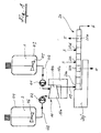
- Fig. 1 is an overall schematic view of a plant for the continuous production of elastomer blends.
- the starting materials are uniformly distributed elastomer particles 1 in a fluid medium, a filler-particle slurry 2 and other components 3.
- the uniformly distributed in the fluid medium elastomer particles, for example, as a solution in a solvent, as emulsified droplets in the fluid medium or as suspended solid or quasi solid particles are present in the fluid medium.
- Suitable elastomers are natural rubber and synthetic rubber.
- Fillers are used, for example, soot particles or silicate particles.
- the other components 3 are, for example, reaction accelerators, plasticizers and vulcanizing agents.
- the elastomer starting materials 1 and the filler raw materials 2 are combined in a first processing area 10 and subjected to a first processing, whereupon they are supplied to a second processing area 20 by being subjected to further processing.
- the further components 3 are supplied and liquid components 4 and gaseous components 5 are removed from the product.
- the finished elastomer mixture 6 is obtained.
- the uniformly distributed in the fluid medium elastomer particles 1 are stored in a container 43 and can be kept in constant motion by means of a stirring tool 45.
- the filler particle slurry 2 is stored in a container 44 and can also be kept constantly in motion by means of a stirring tool 46.
- Via a metering pump 41 which is connected in a line 47 for the elastomeric material, the uniformly distributed elastomer particles 1 are supplied with their fluid medium to the first processing area 10.
- Via a line 48 in which a metering pump 42 is connected the filler particle slurry 2 is supplied to the first processing area 10.
- the first processing section 10 is formed by a mill such as an agitated ball mill or a centrifugal mill.
- a conical agitator ball mill 10 is schematically indicated.
- the first processing area 10 formed by it has a first partial area 10a and a second partial area 10b.
- the first portion 10a is located on the side of the wide end of the truncated cone, while the second portion 10b is located on the side of the narrow end of the truncated cone.
- the filler particle slurry 2 is supplied in the first portion 10a of the first processing portion 10, while the elastomer emulsion or elastomer suspension 1 is supplied in the second portion 10b of the first processing portion.
- the filler particle slurry 2 is longer in the first processing area than the elastomer emulsion or elastomer suspension 1.
- the filler particles 2 of the dividing and distributing effect of the first processing area exposed longer than the elastomer particles.
- the filler particles 2 are brought to the correct or desired size before the start of their incorporation into the elastomer particles 1.
- the incorporation of the filler particles 2 into the elastomer particles 1 begins in the second subregion 10b.
- the amount of initial comminution and distribution of the filler particles 2, as well as the extent of the initial incorporation, can be determined by means of the drive 10c of the mill forming the first processing area 10 and the respective metering locations in the first processing area 10 (first portion 10a, second portion 10b). "Pre-incorporation") of the filler particles 2 in the elastomer particles 1 control.
- the intermediate product thus obtained is supplied from the first processing region 10 via a line 49 to the second processing region 20.
- a multi-shaft extruder in particular a twin-screw extruder or a ring extruder.
- the intermediate product from the first processing area 10 enters an introduction area 20a in the second processing area.
- this second processing area further fragmentation, distribution and incorporation of the filler particles into the elastomer particles takes place. Since the elastomer particles 1 are still surrounded by a sufficient amount of liquid, in particular cooling water, only a moderate warming of the product takes place, so that the elastomer particles 1 are protected against overheating.
- the product is increasingly thickened and concentrated.
- the further components eg reaction accelerator, plasticizer, vulcanizing agent, etc.
- the temperature of the product is always below the vulcanization temperature to prevent premature vulcanization of the product.
- the product is between the the first metering point 20c and the second metering point 20d are melted, so that a portion of the further components before melting and a further portion of the further components is metered after the melting.
- the filler particles 2 and the other components 3 are now evenly distributed in an elastomer matrix.
- gaseous components 5 for example water vapor and other volatile reaction products, are removed from the elastomer melt in a degassing region 20e located further downstream.
- this vulcanization-added "vulcanization-ready" elastomer melt is cooled and brought into a desired shape.
- a solidified finished elastomeric mixture 6 is obtained, which can be brought into any shape during its cooling at the end of the second processing area 20.
- the finished elastomer composition will be a "hide", strand or granule.
- Particularly advantageous is the granular form for the finished elastomer mixture 6, since it can be used as a comfortable starting material for the production of specially shaped rubber articles.
- the procedure for the production of these rubber products then corresponds substantially to the procedure for the production of thermoplastic articles from thermoplastic granules.
- the second processing region 20 as a third processing region, can be followed by a vulcanization line (not shown), along which the extruded elastomer mixture is gradually vulcanized.
- a vulcanization line (not shown), along which the extruded elastomer mixture is gradually vulcanized.
- FIGS. 2A and 2B each schematically show an embodiment of the first processing region of the system of FIG. 1.
- FIG. 2A shows a cylinder 11 and a cone 12 concentric therewith, which define a jacket-shaped cavity. In this cavity protrude pin-like projections 17 and 18 which extend from the surface of the cylinder or the cone.
- the cylinder 11 can serve as a stator, while the cone 12 operates as a rotor. Alternatively, both the cylinder 11 and the cone 12 can be operated as a rotor, between the rotational speeds, however, there is a difference.
- the product can either be conveyed through the cavity by the centrifugal force from right to left, or it can be against this centrifugal force be pumped from left to right through the cavity by a pump (not shown). Both by the choice of the direction of the product and by the selection of the metering points for the various product components, an optimal processing of the product in this first processing region 10 can be achieved.
- FIG. 2B shows a further embodiment of the first processing region 10.
- One uses here an inner cone 13 and an outer cone 14, between which the processing space is formed.
- pin-like elevations 17 and 18 protrude from the surface of the inner or outer cone into the processing area.
- the processing area 10 also contains collision bodies or grinding bodies 19, which are accumulated by the centrifugal action, preferably in the first subarea 10a of the first processing area 10.
- the filler particles 2 are preferably metered in in the first subregion 10a, while the elastomer particles are preferably added in the second subregion 10b.
- the elastomer-filler mixture to be processed is then pumped from left to right through the first processing area 10 against the centrifugal action of the rotating cones 13 and 14.
- the filler particles 2 undergo intensive comminution in the first subarea 10a, both by the influence of the collision bodies 19 and by the influence of the pin-like elevations 17, 18, while in the subsequent second subarea 10b the incorporation of the filler particles 2 into the elastomer particles 1 predominantly occurs , In other words, this means that in the first portion 10a, in which there is a high concentration of grinding media 19, predominantly the fragmentation of the filler 2 takes place, while in the subsequent portion 10b mainly the incorporation of the divided in the region 10a filler 2 in the here dosed elastomer particles 1 takes place.
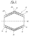
- Fig. 3 shows schematically a further embodiment of the first processing area of the system of Fig. 1.
- the processing area 10 is in this case by an inner, preferably rotatable double cone 15 and an outer, preferably fixed Double cone 16 formed.
- pin-like elevations 17, 18 also protrude into the processing space here.
- the collision bodies / grinding bodies 19 are arranged predominantly in the region radially farthest from the axis of rotation A.
- the filler particles 2 are pumped in the first portion 10a of the processing area 10 against the rotational centrifugal effect.
- the filler particles 2 must then traverse the "swarm" of collision bodies / grinding bodies 19 against the centrifugal action and are thereby intensively comminuted.
- elastomer particles 1 are then preferably supplied to the left and to the right.
- the elastomer particles 1 miss the bombardment by the collision body 19. Consequently, also in the first portion 10a, primarily the filler particles 2 are comminuted, while in the portion 10b the previously comminuted filler particles are incorporated into the elastomer particles 1 added there.
- Both the pin-like elevations 17, 18 and the Kollisions EisenlMahlMech 19 are responsible for the comminution, while only the pin-like elevations 17, 18 are responsible for incorporation.
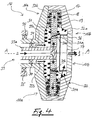
- FIG. 4 schematically shows a further embodiment of the first subsection of the system of FIG. 1.
- FIG. 4 shows a further advantageous geometry for the first processing region 10.
- the crushing and incorporation mill shown here consists of a first rotor 31 and a second rotor 32, which are rotatably mounted about a rotation axis A relative to one another by means of a bearing 34 for the first rotor and by means of a bearing 35 for the second rotor.
- the second rotor 32 consists of two partial areas 32a, 32b, which are connected to each other in a rotationally fixed manner.
- the processing area 10 consists of a radially outer first processing area 10a and a radially inner second processing area 10b.
- a product inlet 33 On the left side is located radially inwardly a product inlet 33, which consists of a product inlet 33a for filler particle slurry 2 and a product inlet 33b for elastomer emulsion or elastomer suspension 1.
- a product outlet 37 Axially displaced on the right side is a product outlet 37 through which both the filler particle slurry 2 and the elastomer emulsion or elastomer suspension 1 emerge.
- a screen 36 In front of the outlet, a screen 36 is mounted, which in addition to the centrifugal effect ("dynamic separation"), the collision body or grinding media 19 in the processing area 10 and preferably retains in its first portion 10a.
- radial channels or tubes 31 b which connect the axial region of the mill with the edge region of the mill.
- axial holes 31 a in the rotor 31 which connect the left half with the right half of the processing area 20 in its second portion 10 b.
- In the region of each of the passages 31 a of the respective radial channel 31 b is in a tube over. In this way, a mixing of the flowing through the channel or the pipe 31 b liquid is prevented with the flowing through the passage 31 a liquid at this intersection.
- both the first rotor 31 and the second rotor 32 are rotated about the axis of rotation A.
- the rotational speed of the first rotor 31 and the rotational speed of the second rotor are different.
- pin-like elevations 17, 18 also extend into the first processing area 10.
- the filler particle slurry 2 (rectilinear arrow) supplied through the inlet 33a flows through the axial passage to the radially inward end of the radial passages 31b of the rotor 31.
- the filler particle slurry 2 then has to pass through the radially outer first portion 10 a of the first processing area 10 and there encounters a high concentration of collision bodies / grinding bodies 19.
- the pin-like elevations 17, 18 and the collision bodies 19 in the radially outer first portion 10a provide for intensive comminution of the filler 2, which now move from the first portion 10a radially inwardly to the second portion 10b.
- This radially inner second portion 10b are due to the centrifugal forces virtually no collision body.
- the elastomer emulsion or elastomer suspension 1 supplied via the inlet region 33b moves only through the radially inner second partial region 10b and is spared by the collision bodies 19.
- first processing area 10 is conceivable to accomplish that in the enriched with Mahl Sciencesn 19 first portion 10a only a crushing of the filler 2 takes place, while in the subsequent second portion 10b a pre-incorporation of the thus comminuted filler 2 takes place in the elastomer particles 1.
- This type of pre-incorporation of filler particles in the elastomer particles is particularly gentle, since it takes place in a well-cooled, preferably aqueous environment.
- the further incorporation of the filler particles into the elastomer particles initially takes place in a readily coolable, preferably aqueous environment, which is thickened only gradually by dehydration.
- two separate mills can also be connected in series, the first with collision / grinding bodies is filled and the downstream second mill has no collision / grinding bodies.
- the filler particle slurry 2 is then introduced into the first ("dicing") mill while the elastomeric particle emulsion / suspension 1 is first introduced into the second (“pre-dip”) mill along with the filler particle slurry 2.
Abstract
Description
Die Erfindung bezieht sich auf ein Verfahren und eine Vorrichtung zum kontinuierlichen Herstellen von Elastomermischungen (Elastomercompounds) gemäss Anspruch 1 bzw. Anspruch 21.The invention relates to a method and a device for the continuous production of elastomer mixtures (elastomer compounds) according to
Elastomermischungen, die aus einer kontinuierlichen Elastomermatrix und einem in die Elastomermatrix eingearbeiteten Füllstoff bestehen, sind Ausgangsprodukte für die Gummiherstellung. Das Elastomer kann z.B. Naturkautschuk oder synthetischer Kautschuk, wie z.B. Nitrylkautschuk sein. Als Füllstoff können z.B. Russpartikel oder Silikatpartikel verwendet werden. Es hat sich gezeigt, dass der Verteilungsgrad und Zerteilungsgrad (Dispersionsgrad) auf die gummitechnischen Eigenschaften einen beachtlichen Einfluss hat. Bei bekannten kontinuierlichen Verfahren zur Herstellung derartiger Elastomermischungen erfolgt dieses dispersive und distributive Mischen sowie das Plastifizieren und/oder Mastifizieren des Füllstoffes bzw. des Elastomers mit Hilfe von Innenmischern.Elastomer blends consisting of a continuous elastomer matrix and a filler incorporated into the elastomer matrix are the raw materials for rubber production. The elastomer may e.g. Natural rubber or synthetic rubber, e.g. Nitryl rubber be. As a filler, e.g. Soot particles or silicate particles are used. It has been shown that the degree of dispersion and degree of dispersion (degree of dispersion) has a considerable influence on the rubber properties. In known continuous processes for the preparation of such elastomer mixtures, this dispersive and distributive mixing and the plastification and / or mastification of the filler or of the elastomer takes place with the aid of internal mixers.
Um die Herstellung von Elastomermischungen für die Gummiindustrie zu vereinfachen, wurde versucht, die traditionellen Darbietungsformen des Natur- oder Synthesekautschuks, wie z.B. die Ballenform, durch flüssiges oder pulverförmiges Elastomer als Rohmaterial zu ersetzen. Zudem ist die partikulierte Darbietungsform die Voraussetzung für eine kontinuierliche Kautschukmischungsherstellung.In order to simplify the production of elastomer blends for the rubber industry, it has been attempted to reduce the traditional performance forms of natural or synthetic rubber, e.g. the bale shape to replace by liquid or powdered elastomer as a raw material. In addition, the particulate form of presentation is the prerequisite for a continuous rubber mix production.
Die Verwendung flüssiger Elastomere wurde bisher nur ansatzweise entwickelt, da dies ein Umdenken und beträchtliche Investitionen seitens der Gummiindustrie erfordert. Elastomere in Pulverform scheinen sich jedoch als Ausgangsmaterial für die Herstellung von Elastomermischungen sowohl im diskontinuierlichen als auch im kontinuierlichen Verfahren zu bewähren. Dies wiederum machte es notwendig, Verfahren für die Herstellung von Pulverkautschuk bereit zustellen. So wurden Verfahren zum Sprühtrocknen und Gefriertrocknen von Nitrylkautschuk oder natürlichem Kautschuk entwickelt. Auch das Verfahren der Blitzverdampfung oder Mahlverfahren wurden verwendet, um kleinere Teilchen zu erzeugen. Ein Nachteil all dieser Verfahren besteht jedoch in der Klebrigkeit und der Kaltfliesseigenschaft der erzeugten Kautschukteilchen. Dennoch wurden Pulverprodukte hergestellt, indem man die Teilchen mit sehr feinen organischen und anorganischen Pulvern einstaubte, um die Kohäsionskräfte zu deaktivieren. Leider wurden durch diese Massnahmen immer wieder ungewollte Verunreinigungen in die hergestellten Teilchen eingetragen.The use of liquid elastomers has been rudimentary so far as it requires rethinking and significant investment by the rubber industry. However, elastomers in powder form appear to prove to be the starting material for the preparation of elastomer blends, both in the batch and in the continuous process. This in turn made it necessary to provide processes for the production of powdered rubber. Thus, methods have been developed for spray-drying and freeze-drying nitrile rubber or natural rubber. The flash evaporation or milling process was also used to produce smaller particles. However, a disadvantage of all these methods is the stickiness and cold flow property of the rubber particles produced. Nevertheless, powder products were made by dusting the particles with very fine organic and inorganic powders to deactivate cohesive forces. Unfortunately, unwanted impurities were repeatedly introduced into the particles produced by these measures.
Folglich wurde ein Verfahren zur Herstellung von Kautschuk/Füllstoff-Mischungen in Pulverform entwickelt. Hierbei wird zuerst eine stabile Kautschuk/Wasser-Emulsion unabhängig von der Art und dem Zustand des Kautschuks gebildet (z.B. Lösungs- oder Emulsions-Polymerisate, Naturkautschuk oder Nitrylkautschuk). Dieser Emulsion wird Füllstoff (Russ oder Silikat) zugefügt, dessen Teilchengrössen-Verteilung zuvor genau eingestellt wurde und der sich zusammen mit verschiedenen Additiven in einer wässrigen Suspension befindet. Die Latex-Emulsion und die Füllstoff-Suspension werden in einem Mischbehälter durch intensives Rühren homogenisiert. Anschliessend wird der Fällungsvorgang bei ständigem Rühren in einem Reaktionsbehälter abgeschlossen, und das gewonnene Fällungsprodukt wird zur weiteren Verarbeitung in einen Homogenisierungsbehälter überführt. Ein Grossteil des Wassers wird dann in einer Zentrifuge entfernt, woraufhin die feinverteilte Mischung bis auf einen Restwassergehalt von weniger als 1 % getrocknet wird. Die so gewonnenen Kautschuk/Füllstoff-Mischungen in Pulverform sind nach dem Trocknen rieselfähig und eignen sich für die Herstellung von Gummiprodukten in einem kontinuierlichen Verfahren.As a result, a process for producing rubber / filler mixtures in powder form has been developed. Here, a stable rubber / water emulsion is first formed regardless of the type and condition of the rubber (e.g., solution or emulsion polymers, natural rubber or nitryl rubber). This emulsion is added filler (carbon black or silicate) whose particle size distribution has previously been precisely adjusted and which is together with various additives in an aqueous suspension. The latex emulsion and the filler suspension are homogenized in a mixing container by intensive stirring. Subsequently, the precipitation process is completed with constant stirring in a reaction vessel, and the recovered precipitate is transferred to further processing in a homogenization vessel. A majority of the water is then removed in a centrifuge, whereupon the finely divided mixture is dried to a residual water content of less than 1%. The thus obtained rubber / filler mixtures in powder form are free-flowing after drying and are suitable for the production of rubber products in a continuous process.
Zur Gummiherstellung bzw. zur Herstellung von Gummiartikeln werden dann die so gewonnen pulverförmigen Kautschuk/Füllstoff-Mischungen in einem Doppelwellenextruder zusammen mit Weichmachern und anderen Beimischungen plastifiziert und/oder mastifiziert ("aufgeschmolzen"), wodurch eine kontinuierliche flüssige Polymermatrix mit in ihr suspendierten Füllstoffteilchen entsteht. Durch Hinzugabe eines Vulkanisationsmittels werden zwischen den Elastomermolekülen Vernetzungen geschaffen, so dass die anschliessend abgekühlte "Masse" des geformten Endproduktes die gewollten gummielastischen Eigenschaften aufweist. Je nach der Art des verwendeten Elastomers, der Art, der Grösse und dem Gehalt der Füllstoffteilchen lassen sich somit massgeschneiderte Gummimischungen herstellen. Hierfür benötigt man mindestens derte Gummimischungen herstellen. Hierfür benötigt man mindestens zwei unterschiedliche pulverförmige Kautschuk/Füllstoff-Mischungen, aus denen man wiederum durch deren geeignetes Mischungsverhältnis untereinander eine grosse Bandbreite von Gummimischungen gewinnen kann.For rubber production or for the production of rubber articles, the powdered rubber / filler mixtures thus obtained are plasticized and / or masticated ("melted") in a twin-screw extruder together with plasticizers and other admixtures, whereby a continuous liquid polymer matrix with filler particles suspended in it is produced , By adding a vulcanizing agent crosslinks are created between the elastomer molecules, so that the subsequently cooled "mass" of the molded end product has the desired rubber-elastic properties. Depending on the type of elastomer used, the type, the size and the content of the filler particles, tailor-made rubber mixtures can thus be produced. For this you need at least derten rubber compounds. For this purpose, at least two different powdered rubber / filler mixtures are required, from which in turn one can obtain a wide range of rubber compounds from one another by virtue of their suitable mixing ratio.
Ein derartiges Verfahren zur Herstellung pulverförmiger, frei fliessender KautschukFüllstoff-Mischungen (Kautschuk/Füllstoff-Batches) ist in der EP-1035155 A1 offenbart. Über eine Suspension mit dem entsprechenden Kautschuk und Russ wird durch Koagulation der Kautschuk und der Russ zu "Granulaten" (Pulverkautschuk) ausgefällt. Der Pulverkautschuk besitzt eine rundliche Form mit einem Durchmesser von 1 bis 3 mm, wobei der Russ das Polymer umgibt. Der Russ liegt bereits in einer vorverteilten Form vor. Der Russ ermöglicht eine einfache Handhabung, insbesondere eine einfache Lagerung und Dosierung.Such a process for producing powdery, free-flowing rubber filler mixtures (rubber / filler batches) is disclosed in EP-1035155 A1. A suspension with the corresponding rubber and carbon black coagulates the rubber and the carbon black into "granules" (powdered rubber). The powder rubber has a roundish shape with a diameter of 1 to 3 mm, with the soot surrounding the polymer. The soot is already in a pre-distributed form. The soot allows easy handling, especially easy storage and dosage.
Grundsätzlich lassen sich mit diesem Verfahren alle wichtigen Kautschuke (natürliche oder künstliche) zu Granulat herstellen. Diverse Zuschlagsstoffe und Weichmacher können in das Granulat eingebaut werden, und vereinfachen dadurch das Zudosieren der Komponenten in das Mischaggregat.In principle, all important rubbers (natural or artificial) can be made into granules using this process. Various additives and plasticizers can be incorporated into the granules, thereby simplifying the metered addition of the components in the mixing unit.
Es hat sich jedoch auch gezeigt, dass die Gummiherstellung ausgehend von pulverförmigen Kautschuk/Füllstoff-Mischungen auch Nachteile besitzt. Betrachtet man nämlich die gesamte Energiebilanz ausgehend vom Naturkautschuk oder künstlichem Kautschuk bis zum Gummi-Endprodukt, so erkennt man, dass diese Art der Gummiherstellung energieintensiv ist. Da das Wasser schon bei der Herstellung des Pulverkautschuks (Kautschuk/Füllstoff-Gemisches) entfernt wird und anschliessend in einem Doppelwellenextruder dieser Pulverkautschuk zusammen mit Vulkanisationsmittel und anderen Beimischungen "aufgeschmolzen" wird, muss für das Aufschmelzen und Einarbeiten der Füllstoffe sehr viel Energie aufgebracht werden. Neben den hohen Energiekosten muss hierbei auch stets darauf geachtet werden, dass die Temperatur des Produktes im Extruder nicht über eine kritische Temperatur ansteigt, da sonst das Elastomer beschädigt werden kann. Die Elastomer-Polymerketten werden dabei durch die hohe Temperatur in kleinere Bruchstücke zerlegt bzw. chemisch modifiziert, und/oder weitere organische Bestandteile, insbesondere Weichmacher werden zersetzt, und/oder in Gegenwart von Vulkanisationsmittel kann eine verfrühte Vernetzung eingeleitet werden.However, it has also been shown that rubber production, starting from powdered rubber / filler mixtures, also has disadvantages. If one looks at the entire energy balance from natural rubber or artificial rubber to the end product of rubber, one recognizes that this type of rubber production is energy-intensive. Since the water is already removed during the production of the powder rubber (rubber / filler mixture) and then in a twin-screw extruder this powder rubber is "melted" together with vulcanizing agent and other admixtures, a lot of energy must be applied for the melting and incorporation of the fillers. In addition to the high energy costs, it must always be ensured that the temperature of the product in the extruder does not rise above a critical temperature, since otherwise the elastomer can be damaged. The elastomer polymer chains are decomposed by the high temperature into smaller fragments or chemically modified, and / or other organic components, in particular plasticizers are decomposed, and / or in the presence of vulcanizing agent premature crosslinking can be initiated.
Derartige Verfahren zur Herstellung von Elastomermischungen sind z.B. in den Dokumenten US 3178390, US 5597235, EP 0 902 057 A2, GB 806362, EP 1 110 691 A2 und GB 623600 beschrieben.Such processes for the preparation of elastomer blends are e.g. in the documents US 3178390, US 5597235, EP 0 902 057 A2, GB 806362, EP 1 110 691 A2 and GB 623600.
Ausgehend von diesen Unzulängllchkeiten des Stands der Technik stellt sich die vorliegende Erfindung die Aufgabe, ein Verfahren zur Herstellung von Elastomennischungen für die Gummiherstellung bereit zustellen, bei dem die oben genannten Probleme des Stands der Technik beseitigt oder zumindest verringert werden.Based on these deficiencies of the prior art, it is the object of the present invention to provide a process for the preparation of elastomer blends for rubber production in which the above-mentioned problems of the prior art are eliminated or at least reduced.
Diese Aufgabe wird durch das Verfahren gemäss Anspruch 1 und die Vorrichtung gemäss Anspruch 21 gelöst.This object is achieved by the method according to
Das Vorliegen des Elastomers in gleichmässig verteilter Form in einem Fluidmedium bewirkt eine geringere Viskosität, solange noch ausreichend viel Fluidmedium in dem zu verarbeitenden Produkt enthalten ist und sorgt durch die Anwesenheit des Fluidmediums, bei dem es sich vorzugsweise um Wasser handelt, gleichzeitig für eine wesentlich bessere Kühlung als bei dem "trockenen" Verfahren des Standes der Technik.The presence of the elastomer in evenly distributed form in a fluid medium results in lower viscosity as long as there is still sufficient fluid medium in the product to be processed, and at the same time provides a substantially better presence by the presence of the fluid medium, which is preferably water Cooling as in the "dry" process of the prior art.
Bei diesem "nassen" Verfahren werden dem in dem ersten Bearbeitungsbereich In Form von Elastomerpartikeln gleichmässig verteilten Elastomer vor dem Zuführen in den zweiten Bearbeitungsbereich Füllstoff-Partikel, insbesondere Russe oder Silikate, zugeführt. Die Einarbeitung der für die Gummiherstellung notwendigen Füllstoffe bzw. Verstärkungsstoffe erfolgt somit zu einem Zeitpunkt, bei dem das zu verarbeitende Produkt aufgrund des noch vorhandenen Fluidmediums in dieser nassen Umgebung noch eine relativ geringe Viskosität hat. Dies ermöglicht es auch, die notwendige Viskosität einzustellen, denn für die Zerteilung der Komponenten wird eine gewisse Scherenergie benötigt. Diese wird u.a. durch die Viskosität beeinflusst. Die Idee besteht darin, eine möglichst geringe Viskosität einzustellen, die noch notwendig ist, damit genügend Scherenergie eingetragen wird. Somit kann man die geringe bzw. für die jeweilige Verfahrensstufe eingestellte Viskosität ausnutzen, um schon vor dem Entwässern und Entgasen eine Ideale Verteilung und Zerteilung der verschiedenen Komponenten im Produkt zu erzielen.In this "wet" process, filler particles, in particular Russian or silicates, are fed to the elastomer which is uniformly distributed in the first processing region in the form of elastomer particles prior to feeding into the second processing region. The incorporation of the fillers or reinforcing materials necessary for rubber production thus takes place at a point in time at which the product to be processed still has a relatively low viscosity in this wet environment due to the fluid medium still present. This also makes it possible to adjust the necessary viscosity, because for the fragmentation of the components a certain amount of shear energy is needed. This is influenced among other things by the viscosity. The idea is to set the lowest possible viscosity, which is still necessary so that enough shear energy is entered. Thus, one can exploit the low or adjusted for each process stage viscosity, even before dewatering and degassing to achieve an ideal distribution and fragmentation of the various components in the product.
Erfindungsgemäss erfolgt die Entfernung der Fluide und/oder Flüssigkeiten in mehreren Entwässerungsschritten während des Durchlaufs des Produktes durch den zweiten Bearbeitungsbereich, wobei insbesondere auch das Einarbeiten von Füllstoff in mehreren Einarbeitungsschritten während des Durchlaufs des Produktes durch den zweiten Bearbeitungsbereich erfolgt.According to the invention, the removal of the fluids and / or liquids in a plurality of dewatering steps during the passage of the product through the second processing area, wherein in particular the incorporation of filler takes place in several stages of incorporation during the passage of the product through the second processing area.
Auf diese Weise wird zu Beginn des Mischvorgangs, wenn noch viele Komponenten in die Elastomermischung eingearbeitet werden müssen, für eine niedrige Viskosität des zu bearbeitenden Produktes gesorgt, während gegen Ende des Mischvorgangs aufgrund der Entwässerung und der Entgasung eine Zunahme der Viskosität erfolgt, die aber zu diesem späten Zeitpunkt im Verfahren akzeptabel ist.In this way, at the beginning of the mixing process, when many components must still be incorporated into the elastomer mixture, a low viscosity of the product to be processed is provided, while towards the end of the mixing process due to the dehydration and the degassing an increase in the viscosity takes place, but This late point in the procedure is acceptable.
Zweckmässigerweise arbeitet man derart, dass die in dem ersten Bearbeitungsbereich wirkenden Scherraten im Bereich von 100/s bis 100'000/s liegen, wobei die Intensität der Scher- und/oder Dehnströmung in dem ersten Bearbeitungsbereich stetig von einem Minimum auf ein Maximum ansteigt und anschliessend stetig oder abrupt wieder abnimmt. Insbesondere ist in dem ersten Bearbeitungsbereich die maximale Scherrate in einem ersten Teilbereich höchstens etwa das 5-fache der minimalen Scherrate in einem zweiten Teilbereich des ersten Bearbeitungsbereichs, und das Volumen des ersten Teilbereichs ist höchstens etwa das 3-fache des Volumens des zweiten Teilbereichs.It is expedient to work in such a way that the shear rates acting in the first processing region are in the range of 100 / s to 100,000 / s, the intensity of the shear and / or extensional flow in the first processing region increasing steadily from a minimum to a maximum, and then steadily or abruptly decreases again. Specifically, in the first processing area, the maximum shear rate in a first partial area is at most about 5 times the minimum shear rate in a second partial area of the first processing area, and the volume of the first partial area is at most about 3 times the volume of the second partial area.
Vorzugsweise werden der aus dem ersten Bearbeitungsbereich in den zweiten Bearbeitungsbereich überführten fliessfähigen Masse im zweiten Bearbeitungsbereich weitere Komponenten, wie z.B. Füllstoffe, Additive, Vulkanisationsmittel, Beschleuniger, Weichmacher und Hilfsmittel, hinzugegeben.Preferably, the flowable mass transferred from the first processing area into the second processing area in the second processing area are further components, such as e.g. Fillers, additives, vulcanizing agents, accelerators, plasticizers and adjuvants added.
Je nach der Art des Elastomers (Naturkautschuk, Synthesekautschuk, etc.) kann das erste Fluidmedium ein Lösungsmittel sein, in dem das Elastomer in gelöster Form vorliegt, oder das Elastomer kann als Emulsion einer Elastomerlösung in einer mit dem Lösungsmittel nicht mischbaren Flüssigkeit vorliegen. Bei Bedarf kann das Elastomer auch als Suspension von Elastomerteilchen in einer Flüssigkeit oder als gelartiger Verbund in einem Lösungsmittel vorliegen.Depending on the nature of the elastomer (natural rubber, synthetic rubber, etc.), the first fluid medium may be a solvent in which the elastomer is in dissolved form, or the elastomer may be present as an emulsion of an elastomer solution in a liquid immiscible with the solvent. If desired, the elastomer may also be present as a suspension of elastomer particles in a liquid or as a gel-like composite in a solvent.
Zweckmässigerweise wird bei Zudosierung von Vulkanisationsmitteln in das Produkt die Produkttemperatur im zweiten Bearbeitungsbereich zumindest förderabseitig von der Zudosierungsstelle unterhalb der Vulkanisationstemperatur gehalten. Dadurch wird verhindert, dass eine Vulkanisation der Elastomermischung schon bei deren Mischungsherstellung erfolgt.Conveniently, when dosing vulcanizing agents in the product, the product temperature in the second processing area is kept at least downstream of the feed point below the vulcanization temperature. This prevents a vulcanization of the elastomer mixture takes place already during their mixture production.
Während die weiteren Komponenten und die Füllstoffe im Bearbeitungsbereich in das Elastomer eingearbeitet und/oder zerteilt und/oder verteilt werden, wird das Produkt im zweiten Bearbeitungsbereich zweckmässigerweise auch schon nach und nach entgast.While the other components and the fillers are incorporated in the processing area in the elastomer and / or divided and / or distributed, the product in the second processing area is conveniently already gradually degassed.
Besonders vorteilhaft ist es auch, wenn die Entfernung der Fluide und/oder Flüssigkeiten aus dem Produkt vor dem Eindosieren des Vulkanisationsmittels erfolgt. Es kann nämlich vorkommen, dass die Gegenwart von Wasser die Reaktivität des Vulkanisatlonsmittels beeinflusst Ausserdem muss am Ende die Mischung wasserfrei vorliegen. Für die Vulkanisation, die nach einer späteren Formgebung eingeleitet wird, werden typischerweise Temperaturen deutlich über 100°C gefahren. Sollte dann immer noch Wasser im Produkt vorhanden sein, führt dies zu einer ggf. gewollten Aufschäumung der sich bildenden Gummimasse.It is also particularly advantageous if the removal of the fluids and / or liquids from the product takes place before the vulcanization agent is metered in. In fact, it may happen that the presence of water influences the reactivity of the vulcanization agent. Finally, the mixture must be anhydrous in the end. For the vulcanization, which is initiated after a later shaping, typically temperatures are well above 100 ° C driven. Should there still be water in the product, this leads to a possibly desired foaming of the forming rubber mass.
Besonders zweckmässig ist es dabei, wenn die Bearbeitungsschritte und die Entwässerungsschritte abwechselnd aufeinander folgen, wobei vorzugsweise während eines Entwässerungsschrittes von den Fluiden und/oder Flüssigkeiten nur so viel aus dem Produkt-entfemt wird, dass für den jeweils nachfolgenden Einarbeitungsschritt eine optimale Einarbeitung erreicht wird.In this case, it is particularly expedient if the processing steps and the dewatering steps follow one another alternately, wherein only as much of the product is removed from the fluids and / or liquids during a dewatering step that optimum incorporation is achieved for the respective subsequent incorporation step.
In der Regel wird man dem Produkt bei dem erfindungsgemässen Verfahren auch ein Koagulationsmittel zuführen. Dies ist besonders zweckmässig, wenn das Produkt beim Austreten aus dem Mischextruder geformt wird, um z.B. anschliessend granuliert oder zu Strangprofilen verarbeitet zu werden. Auf diese Weise erhält man ein unter geeigneten Bedingungen umformbares und noch nicht vulkanisiertes Ausgangsprodukt, das nach seiner Umformung in einem letzten Schritt vulkanisiert werden kann. Ähnlich wie bei der Herstellung von Kunststoffartikeln aus Thermoplasten bietet sich damit eine sehr komfortable Weiterverarbeitung der noch nicht vulkanisierten, in Granulatform vorliegenden Elastomere zu fertigen, d.h. vulkanisierten und umgeformten Gummiprodukten.As a rule, a coagulant will also be added to the product in the process according to the invention. This is particularly useful when the product is formed on exit from the compounding extruder, for example, subsequently granulated or to be processed into extruded profiles. In this way, a recoverable under suitable conditions and not yet vulcanized starting material, which can be vulcanized after its transformation in a final step. Similar to the production of plastic articles made of thermoplastics, this makes it possible to produce very uncomplicated further processing of the as yet uncured elastomers present in granulate form, ie vulcanized and shaped rubber products.
Um bei der erfindungsgemässen Vorrichtung in dem ersten Bearbeitungsbereich die weiter oben erwähnten Scherraten zu erzielen, verwendet man für den ersten Bearbeitungsbereich einen Zwischenraum zwischen zwei koaxialen Drehelementen, die relativ zu einander um ihre gemeinsame Achse drehbar sind. Bei den beiden koaxialen Drehelementen kann es sich dabei z.B. um ein Zylinder-Konus-Paar, um ein Konus-Konus-Paar oder z.B. um ein Doppelkonus-Doppelkonus-Paar handeln, wobei sich der Zwischenraum zwischen den koaxialen Drehelementen in der Produkt-Förderrichtung verjüngt oder erweitert. Für den Konus sind prinzipiell Öffnungswinkel zwischen 0 und 180° denkbar, wobei vorzugsweise Öffnungswinkel unter 90° realisiert werden.In order to achieve the above-mentioned shear rates in the device according to the invention in the first processing region, a space is used for the first processing region between two coaxial rotary elements which are rotatable relative to each other about their common axis. The two coaxial rotating elements may be e.g. a cylinder-cone pair, a cone-cone pair or e.g. to act a double-cone double-cone pair, wherein the intermediate space between the coaxial rotary elements in the product conveying direction tapers or expands. For the cone opening angle between 0 and 180 ° are in principle conceivable, preferably opening angles are realized below 90 °.
Zweckmässigerweise ist eines der Drehelemente ein Rotor und das andere ein Stator. Alternativ können aber auch beide Drehelemente Rotoren sein, die mit unterschiedlichen Drehgeschwindigkeiten antreibbar sind.Conveniently, one of the rotary elements is a rotor and the other is a stator. Alternatively, however, both rotary elements can be rotors which can be driven at different rotational speeds.
Zweckmässigerweise erstrecken sich von der Oberfläche des jeweiligen Drehelements stiftartige Erhebungen in den Zwischenraum hinein, die sich bei Drehung der Drehelemente aneinander vorbei bewegen.Expediently, pin-like elevations extend from the surface of the respective rotary element into the intermediate space, which move past one another upon rotation of the rotary elements.
Vorzugsweise befinden sich in dem Zwischenraum auch noch Kollisionskörper, die mit der Oberfläche und/oder den stiftartigen Erhebungen der Drehelemente und/oder dem Produkt zusammenstossen können. Als Kollisionskörper bzw. Mahlkörper verwendet man z.B. Kügelchen aus Stahl oder Kunststoff, deren Masse bzw. Grösse an die angestrebte Korngrössenverteilung des Produktes angepasst sind.Preferably, collision bodies which can collide with the surface and / or the pin-like elevations of the rotary elements and / or the product are also located in the intermediate space. As a collision body or grinding media used, for example. Beads of steel or plastic whose mass or size are adapted to the desired grain size distribution of the product.
Für den ersten Bearbeitungsbereich können auch Rührwerkskugelmühlen der sog. K-Serie (K8, K60, K120, K240) der Anmelderin oder eine Zentrifugalmühle (Modell ZR120) der Anmelderin verwendet werden. Somit werden die dem ersten Bearbeitungsbereich zugeführten Füllstoff- und Elestornerpartikel durch Nassvermahlung aufbereitet, bevor sie dem zweiten Bearbeitungsbereich zugeführt werden. Auf diese Weise wird vermieden, dass die für die Verteilung und Zerteilung der Verstärkungsstoffe verwendete und z.T. in Wärme umgewandelte Energie nicht unmittelbar dem Elastomer zugeführt wird, dieses also thermisch geschont wird.Agitator ball mills of the so-called K series (K8, K60, K120, K240) of the Applicant or a centrifugal mill (Model ZR120) of the Applicant. Thus, the filler and Elestorner particles supplied to the first processing area are wet-grounded before being fed to the second processing area. In this way, it is avoided that the energy used for the distribution and division of the reinforcing materials and partly converted into heat is not directly supplied to the elastomer, that is, it is thermally protected.
Bei der erfindungsgemässen Vorrichtung verwendet man zweckmässigerweise als zweiten Bearbeitungsbereich den Prozessraum eines Mischextruders, insbesondere eines Mehrwellen-Extruders. Besonders vorteilhaft ist ein dichtkämmender, gleichsinnig drehender Mehrwellen-Extruder, insbesondere auch ein Ringextruder.In the device according to the invention, the process space of a mixing extruder, in particular a multi-screw extruder, is expediently used as the second processing area. Particularly advantageous is a close-meshed, co-rotating multi-shaft extruder, in particular a ring extruder.
Bei der besonders vorteilhaften Ausgestaltung der erfindungsgemässen Vorrichtung weist der Mehrwellen-Extruder mindestens eine seitliche Öffnung auf, in die jeweils ein zu ihr hin fördernder Seitenextruder mündet, wobei der eine bzw. die mehreren Entwässerungsschritte an der einen bzw. den mehreren seitlichen Öffnungen entlang der Produkt-Durchlaufrichtung entlang des Mischextruders erfolgen. Dieser Seitenextruder ermöglicht es freiwerdendem Wasser, aus dem Produkt entgegen der Förderrichtung des Seitenextruders zu entweichen, während das Elastornermaterial durch den Seitenextruder im Mischextruder stets zurückgehalten wird.In the particularly advantageous embodiment of the device according to the invention, the multi-screw extruder has at least one lateral opening, into each of which a side extruder conveying to it opens, wherein the one or more dewatering steps at the one or more lateral openings along the product -Passage direction along the mixing extruder. This side extruder allows released water to escape from the product in the opposite direction to the conveying direction of the side extruder, while the elastomer material is always retained by the side extruder in the mixing extruder.
Als vorteilhafte Ergänzung zu dem erfindungsgemässen Verfahren kann das aus dem zweiten Bearbeitungsbereich austretende und mit Vulkanisationamitteln versehene Produkt in einem dritten Bearbeitungsbereich zu einem kontinuierlichen Profilstrang geformt und ausvulkanisiert werden. Je nach Bedarf kann dieser kontinuierliche Profilstrang in Profile mit bestimmter Länge geschnitten werden. Hierfür weist die erfindungsgemässe Vorrichtung einen dem zweiten Bearbeitungsbereich nachgeschalteten dritten Bearbeitungsbereich auf, der insbesondere als Vulkanlsationsstrecke ausgebildet ist. Das für die Herstellung von Gummilangwaren aus dem Mischextruder austretende Produkt wird dann entlang der Vulkanisationsstrecke derart temperiert, dass eine kontinuierliche Vernetzung der Polymere stattfindet Für den speziellen Fall der Gummilangwaren, wie z.B. Profile, verfügt man somit über einen vollständig kontinuierlichen Prozess ausgehend von den Rohstoffen Latex und Füllstoff mit anfänglich viel Wasser bzw. organischem Lösungsmittel bis hin zu dem fertig geformten, entwässerten und schliesslich vernetzten Gummilangwaren-Endprodukt.As an advantageous supplement to the process according to the invention, the product emerging from the second processing region and provided with vulcanization agents can be formed into a continuous profile strand and vulcanized in a third processing region. Depending on requirements, this continuous profile strand can be cut into profiles of a certain length. For this purpose, the device according to the invention has a third processing area downstream of the second processing area, which is designed in particular as a vulcanization path. The product emerging from the compounding extruder for the production of rubber articles is then tempered along the vulcanization line in such a way that a continuous crosslinking of the polymers takes place. For the special case of rubber articles, such as profiles, a completely continuous process is thus obtained starting from the raw materials latex and filler with initially a lot of water or organic solvent to the finished molded, dewatered and finally cross-linked gum end product.
Bei einer besonders einfachen Ausführung des erfindungsgemässen Verfahrens ist der erste Bearbeitungsbereich ein erster Abschnitt eines Extruders und der zweite Bearbeitungsbereich ein zweiter Abschnitt desselben Extruders, bei dem es sich insbesondere um einen Mehrwellen-Extruder handelt. Bei einer alternativen Ausführung des erfindungsgemässen Verfahrens kann der erste Bearbeitungsbereich einen ersten Teilextruder aufweisen, durch den das in Form gleichmässig verteilter Partikel in dem Fluidmedium vorliegende Elastomer bearbeitet wird, und einen zweiten Teilextruder aufweisen, durch den die Füllstoffpartikel enthaltende Aufschlämmung bearbeitet wird. Dies ermöglicht es, den ersten Teilextruder speziell derart zu gestalten, dass er die gleichmässige Verteilung der emulgierten bzw. suspendierten Elastomerpartikel in dem Fluidmedium ermöglicht, und den zweiten Teilextruder derart speziell zu gestalten, dass eine optimale Zerteilung der Füllstoffpartikel in der Aufschlämmung erzielt werden kann.In a particularly simple embodiment of the method according to the invention, the first processing region is a first section of an extruder and the second processing region is a second section of the same extruder, which in particular is a multi-shaft extruder. In an alternative embodiment of the method according to the invention, the first processing region may comprise a first part extruder through which the elastomer in the form of uniformly distributed particles is processed in the fluid medium and have a second part extruder through which the slurry containing the filler particles is processed. This makes it possible to design the first part extruder specifically so as to allow the uniform distribution of the emulsified or suspended elastomer particles in the fluid medium, and to design the second part extruder so that optimum fragmentation of the filler particles in the slurry can be achieved.
Der erste Teilextruder und der zweite Teilextruder des ersten Bearbeitungsbereichs können parallel oder in Serie geschaltet sein. Die verfahrensmässige Parallelschaltung lässt sich z.B. dadurch erzielen, dass ein Seitenextruder in einen Hauptextruder einmündet, so dass der Seitenextruder den einen der beiden Teilextruder bildet und der von der Einmündung des einen Teilextruders stromauf gelegene Abschnitt des Hauptextruders den anderen Teilextruder bildet.The first part extruder and the second part extruder of the first processing area may be connected in parallel or in series. The procedural parallel connection can be e.g. in that a side extruder leads into a main extruder so that the side extruder forms one of the two part extruders and the section of the main extruder upstream from the mouth of one part extruder forms the other part extruder.
Bei den genannten Ausführungen, in denen der erste Bearbeitungsbereich einen ersten und einen zweiten Teilextruder aufweist, ist der zweite Bearbeitungsbereich ebenfalls vorzugsweise ein Extruder, insbesondere ein Ringextruder.In the aforementioned embodiments, in which the first processing region has a first and a second part extruder, the second processing region is also preferably an extruder, in particular a ring extruder.
Bei einer weiterführenden Ausführung der erfindungsgemässen Vorrichtung weist der erste Bearbeitungsbereich mindestens einen Einwellenextruder und/oder mindestens einen Zweiwellenextruder auf, deren Achsen jeweils kollinear mit einer Achse der Wellen des Ringextruders sind. Dies ermöglicht es, die Wellen des mindestens einen Einwellenextruders und des mindestens einen Zweiwellenextruders mit den jeweils kollinearen Wellen des Ringextruders einstückig auszubilden, so dass sämtliche Wellen der Einwellenextruder, der Zweiwellenextruder und des Ringextruders beider Bearbeitungsbereiche gemeinsam antreibbar sind. Diese Ausführung mit gesonderten, zu einander parallel angeordneten Extrudern im ersten Bearbeitungsbereich ermöglicht es, die verschiedenen Ausgangsstoffe (Elastomer, Füllstoff, weitere Komponenten) in dem ersten Bearbeitungsbereich jeweils einer ersten Bearbeitung unabhängig von den weiteren Ausgangsstoffen bzw. Komponenten durchzuführen. Erst beim Verlassen des ersten Bearbeitungsbereichs (Einwellenextruder, Zweiwellenextruder) gelangen die so vorbereiteten Ausgangsstoffe bzw. weiteren Komponenten in den durch den Ringextruder gebildeten zweiten Bearbeitungsbereich, in dem dann sämtlich Ausgangsstoffe und weiteren Komponenten miteinander vermischt und gemeinsam bearbeitet werden.In a further embodiment of the device according to the invention, the first processing region has at least one single-screw extruder and / or at least one twin-screw extruder whose axes are in each case collinear with an axis of the shafts of the ring extruder. This makes it possible to form the shafts of the at least one single-screw extruder and the at least one twin-screw extruder in one piece with the respective collinear waves of the ring extruder, so that all the waves of the Single-screw extruder, the twin-screw extruder and the ring extruder of both processing areas are driven together. This embodiment with separate, parallel to each other arranged extruders in the first processing area makes it possible to perform the different starting materials (elastomer, filler, other components) in the first processing area each of a first processing independently of the other starting materials or components. Only when leaving the first processing area (single-screw extruder, twin-screw extruder) are the starting materials or further components prepared in the second processing area formed by the ring extruder, in which then all starting materials and other components are mixed together and processed together.
Weitere Vorteile, Merkmale und Anwendungsmöglichkeiten ergeben sich aus der nun folgenden Beschreibung anhand mehrerer Ausführungsbeispiele der Erfindung.
- Fig. 1
- ist eine schematische Gesamtansicht einer erfindungsgemässen Anlage zur Durchführung des erfindungsgemässen Verfahrens.
- Fig. 2A und 2B
- zeigen jeweils schematisch eine Ausführung eines ersten Teils der Anlage von Fig. 1.
- Fig. 3
- zeigt schematisch eine weitere Ausführung des ersten Teils der Anlage von Fig. 1.
- Fig. 4
- zeigt schematisch eine weitere Ausführung des ersten Teils der Anlage von Fig. 1.
- Fig. 1
- is a schematic overall view of a system according to the invention for carrying out the inventive method.
- FIGS. 2A and 2B
- each show schematically an embodiment of a first part of the system of FIG. 1.
- Fig. 3
- schematically shows a further embodiment of the first part of the system of FIG. 1.
- Fig. 4
- schematically shows a further embodiment of the first part of the system of FIG. 1.
Fig. 1 ist eine schematische Gesamtansicht einer Anlage zum kontinuierlichen Herstellen von Elastomermischungen. Die Ausgangsstoffe sind gleichmässig verteilte Elastomerpartikel 1 in einem Fluidmedium, eine Füllstoff-Partikel-Aufschlämmung 2 sowie weitere Komponenten 3. Die in dem Fluidmedium gleichmässig verteilten Elastomerpartikel können z.B. als Lösung in einem Lösungsmittel, als emulgierte Tröpfchen in dem Fluidmedium oder als suspendierte feste oder quasi-feste Teilchen in dem Fluidmedium vorliegen. Als Elastomer kommen Naturkautschuk und Synthesekautschuk in Frage. Als Füllstoff verwendet man z.B. Russpartikel oder Silikatpartikel. Die weiteren Komponenten 3 sind z.B. Reaktionsbeschleuniger, Weichmacher und Vulkanisationsmittel.Fig. 1 is an overall schematic view of a plant for the continuous production of elastomer blends. The starting materials are uniformly distributed
Die Elastomer-Ausgangsstoffe 1 und die Füllstoff-Ausgangsstoffe 2 werden in einem ersten Bearbeitungsbereich 10 zusammengeführt und einer ersten Bearbeitung unterzogen, woraufhin sie einem zweiten Bearbeitungsbereich 20 zugeführt werden, indem sie einer weiteren Bearbeitung unterzogen werden. In dem zweiten Bearbeitungsbereich 20 werden die weiteren Komponenten 3 zugeführt und flüssige Komponenten 4 sowie gasförmige Komponenten 5 aus dem Produkt entzogen. Am Ende des zweiten Bearbeitungsbereichs 20 erhält man die fertige Elastomermischung 6.The
Die in dem Fluidmedium gleichmässig verteilten Elastomerpartikel 1 werden in einem Behälter 43 aufbewahrt und können mittels eines Rührwerkzeuges 45 ständig in Bewegung gehalten werden. Die Füllstoffpartikel-Aufschlämmung 2 wird in einem Behälter 44 gelagert und kann ebenfalls mittels eines Rührwerkzeuges 46 ständig in Bewegung gehalten werden. Über eine Dosierpumpe 41, die in einer Leitung 47 für das Elastomermaterial geschaltet ist, werden die gleichmässig verteilten Elastomerpartikel 1 mit ihrem Fluidmedium dem ersten Bearbeitungsbereich 10 zugeführt. Über eine Leitung 48, in der eine Dosierpumpe 42 geschaltet ist, wird die Füllstoffpartikel-Aufschlämmung 2 dem ersten Bearbeitungsbereich 10 zugeführt.The uniformly distributed in the fluid
Der erste Bearbeitungsbereich 10 wird durch eine Mühle, wie z.B. einer Rührwerkskugelmühle oder eine Zentrifugalmühle gebildet. In Fig. 1 ist eine konische Rührwerkskugelmühle 10 schematisch angedeutet. Der durch sie gebildete erste Bearbeitungsbereich 10 besitzt einen ersten Teilbereich 10a und eine zweiten Teilbereich 10b. Der erste Teilbereich 10a befindet sich dabei auf der Seite des breiten Endes des Kegelstumpfes, während sich der zweite Teilbereich 10b auf der Seite des schmalen Endes des Kegelstumpfes befindet. Die Füllstoffpartikel-Aufschlämmung 2 wird im ersten Teilbereich 10a des ersten Bearbeitungsbereichs 10 zugeführt, während die Elastomeremulsion bzw. Elastomersuspension 1 im zweiten Teilbereich 10b des ersten Bearbeitungsbereichs zugeführt wird. Auf diese Weise befindet sich die Füllstoffpartikel-Aufschlämmung 2 länger im ersten Bearbeitungsbereich als die Elastomeremulsion bzw. Elastomersuspension 1. Somit werden die Füllstoffpartikel 2 der zerteilenden und verteilenden Wirkung des ersten Bearbeitungsbereichs länger ausgesetzt als die Elastomerpartikel. Somit werden die Füllstoffpartikel 2 vor dem Beginn ihrer Einarbeitung in die Elastomerpartikel 1 auf die richtige bzw. angestrebte Grösse gebracht. Nachdem die Grösse der Füllstoffpartikel 2 im ersten Teilbereich 10a eingestellt worden ist, setzt im zweiten Teilbereich 10b die Einarbeitung der Füllstoffpartikel 2 in die Elastomerpartikel 1 ein. Über den Antrieb 10c der den ersten Bearbeitungsbereichs 10 bildenden Mühle sowie über die jeweiligen Zudosierungsorte in dem ersten Bearbeitungsbereich 10 (erster Teilbereich 10a, zweiter Teilbereich 10b) lässt sich das Ausmass der anfänglichen Zerkleinerung und Verteilung der Füllstoffpartikel 2, sowie das Ausmass der anfänglichen Einarbeitung ("Vorab-Einarbeitung") der Füllstoffpartikel 2 in die Elastomerpartikel 1 steuern.The
Das so gewonnene Zwischenprodukt wird aus dem ersten Bearbeitungsbereich 10 über eine Leitung 49 dem zweiten Bearbeitungsbereich 20 zugeführt. Für den zweiten Bearbeitungsbereich verwendet man einen Mehrwellen-Extruder, insbesondere einem Zweiwellenextruder oder einen Ringextruder. Das Zwischenprodukt aus dem ersten Bearbeitungsbereich 10 gelangt in einen Einleitungsbereich 20a in dem zweiten Bearbeitungsbereich. In diesem zweiten Bearbeitungsbereich findet eine weitere Zerteilung, Verteilung und Einarbeitung der Füllstoffpartikel in die Elastomerpartikel statt. Da die Elastomerpartikel 1 noch mit ausreichend viel Flüssigkeit, insbesondere kühlendem Wasser, umgeben sind, findet nur eine mässige Erwärmung des Produktes statt, so dass die Elastomerpartikel 1 vor Überhitzung geschützt sind. In einem stromab in dem zweiten Bearbeitungsbereich 20 angeordneten Entwässerungsbereich 20b wird ein Grossteil der flüssigen Komponenten 4, hauptsächlich Wasser, entzogen. Dadurch wird das Produkt zunehmend eingedickt und konzentriert. Nun liegen vorwiegend Elastomerpartikel 1 und Füllstoffpartikel 2 mit nur noch geringen Mengen an organischem Lösungsmittel und Wasser vor. Weiter stromab im zweiten Bearbeitungsbereich 20 befinden sich eine erste Zudosierungsstelle 20c und eine zweite Zudosierungsstelle 20d, in denen die weiteren Komponenten (z.B. Reaktionsbeschleuniger, Weichmacher, Vulkanisationsmittel etc.) zudosiert werden. Sobald Vulkanisationsmittel zudosiert worden ist, muss darauf geachtet werden, dass im Bearbeitungsbereich 20 die Temperatur des Produktes stets unterhalb der Vulkanisationstemperatur liegt, um ein vorzeitiges Vulkanisieren des Produktes zu verhindern. Vorzugsweise wird das Produkt zwischen der ersten Zudosierungsstelle 20c und der zweiten Zudosierungsstelle 20d aufgeschmolzen, so dass ein Teil der weiteren Komponenten vor dem Aufschmelzen und ein weiterer Teil der weiteren Komponenten nach dem Aufschmelzen zudosiert wird. Die Füllstoffpartikel 2 und die weiteren Komponenten 3 sind nun in einer Elastomermatrix gleichmässig verteilt. Aus dieser ständig unter der Vulkanisationstemperatur gehaltenen Elastomerschmelze werden in einem weiter stromab gelegenen Entgasungsbereich 20e gasförmige Komponenten 5, wie z.B. Wasserdampf und andere flüchtige Reaktionsprodukte aus der Elastomerschmelze entfernt. Am Ende des zweiten Bearbeitungsbereichs 20 wird diese mit Vulkanisationsmittel versetzte "vulkanisationsbereite" Elastomerschmelze abgekühlt und in eine gewünschte Form gebracht. Somit erhält man eine verfestigte fertige Elastomermischung 6, die während ihres Abkühlens am Ende des zweiten Bearbeitungsbereich 20 in eine beliebige Form gebracht werden kann. Je nach der verwendeten Formgebungsvorrichtung (nicht gezeigt) fällt die fertige Elastomermischung als "Fell", Strang oder Granulat an. Besonders vorteilhaft ist die Granulatform für die fertige Elastomermischung 6, da sie als komfortables Ausgangsprodukt für die Fertigung speziell geformter Gummiartikel verwendet werden kann. Die Vorgehensweise für die Herstellung dieser Gummiartikel entspricht dann im wesentlichen der Vorgehensweise für die Herstellung von Thermoplastartikeln aus Thermoplast-Granulat. Zur Herstellung von Gummilangwaren, wie z.B. Profilsträngen kann dem zweiten Bearbeitungsbereich 20 als dritter Bearbeitungsbereich eine Vulkanisationsstrecke (nicht gezeigt) nachgeschaltet werden, entlang der die stranggeformte Elastomermischung nach und nach vulkanisiert wird. Somit lassen sich Gummiprofile in einem völlig kontinuierlichen Verfahren herstellen.The intermediate product thus obtained is supplied from the
Fig. 2A und 2B zeigen jeweils schematisch eine Ausführung des ersten Bearbeitungsbereichs der Anlage von Fig. 1. Fig. 2A zeigt einen Zylinder 11 und einen mit ihm konzentrischen Konus 12, die einen mantelförmigen Hohlraum bestimmen. In diesen Hohlraum ragen stiftartige Erhebungen 17 und 18, die sich von der Oberfläche des Zylinders bzw. des Konus erstrecken. Der Zylinder 11 kann dabei als Stator dienen, während der Konus 12 als Rotor arbeitet. Alternativ können sowohl der Zylinder 11 als auch der Konus 12 als Rotor betrieben werden, zwischen deren Drehgeschwindigkeiten jedoch eine Differenz besteht. Das Produkt kann entweder durch die Zentrifugalkraft von rechts nach links durch den Hohlraum befördert werden, oder es kann entgegen dieser Zentrifugalkraft durch eine (nicht gezeigte) Pumpe von links nach rechts durch den Hohlraum befördert werden. Sowohl durch die Wahl der Produktrichtung als auch durch die Auswahl der Zudosierungsstellen für die verschiedenen Produktkomponenten lässt sich eine optimale Bearbeitung des Produktes in diesem ersten Bearbeitungsbereich 10 erreichen.FIGS. 2A and 2B each schematically show an embodiment of the first processing region of the system of FIG. 1. FIG. 2A shows a cylinder 11 and a
In Fig. 2B ist eine weitere Ausführung des ersten Bearbeitungsbereichs 10 gezeigt. Man verwendet hier einen inneren Konus 13 und einen äusseren Konus 14, zwischen denen der Bearbeitungsraum gebildet wird. Auch hier ragen stiftartige Erhebungen 17 und 18 von der Oberfläche des inneren bzw. äusseren Konus in den Bearbeitungsbereich. Der Bearbeitungsbereich 10 enthält ausserdem Kollisionskörper bzw. Mahlkörper 19, die durch die Zentrifugalwirkung vorzugsweise im ersten Teilbereich 10a des ersten Bearbeitungsbereichs 10 angehäuft sind. Wie schon bei Fig. 1 erwähnt, werden die Füllstoffpartikel 2 vorzugsweise im ersten Teilbereich 10a zudosiert, während die Elastomerpartikel vorzugsweise im zweiten Teilbereich 10b zudosiert werden. Die zu bearbeitende Elastomer-Füllstoff-Mischung wird dann entgegen der Zentrifugalwirkung der rotierenden Konen 13 und 14 von links nach rechts durch den ersten Bearbeitungsbereich 10 gepumpt. Auf diese Weise erfahren die Füllstoffpartikel 2 sowohl durch den Einfluss der Kollisionskörper 19 als auch durch den Einfluss der stiftartigen Erhebungen 17, 18 eine intensive Zerkleinerung im ersten Teilbereich 10a, während im anschliessenden zweiten Teilbereich 10b vorwiegend die Einarbeitung der Füllstoffpartikel 2 in die Elastomerpartikel 1 erfolgt. Mit anderen Worten bedeutet dies, dass im ersten Teilbereich 10a, in dem eine hohe Konzentration an Mahlkörpern 19 vorliegt, vorwiegend die Zerteilung der Füllstoffpartikel 2 stattfindet, während im anschliessenden Teilbereich 10b vorwiegend die Einarbeitung der im Bereich 10a zerteilten Füllstoffpartikel 2 in die hier zudosierten Elastomerpartikel 1 stattfindet. Somit wird verhindert oder zumindest unwahrscheinlich gemacht, dass die weichen Elastomerpartikel 1 durch Kollisionskörper/Mahlkörper 19 getroffen werden. Auf diese Weise wird vermieden, dass Mahlkörper 19 anstelle von Füllstoffpartikeln 2 in die Elastomerpartikel 1 eingearbeitet werden.FIG. 2B shows a further embodiment of the
Fig. 3 zeigt schematisch eine weitere Ausführung des ersten Bearbeitungsbereichs der Anlage von Fig. 1. Der Bearbeitungsbereich 10 wird hierbei durch einen inneren, vorzugsweise drehbaren Doppelkonus 15 und einen äusseren, vorzugsweise feststehenden Doppelkonus 16 gebildet. Wie schon in Fig. 2A und 2B ragen auch hier stiftartige Erhebungen 17, 18 in den Bearbeitungsraum. Auch hier sind aufgrund der Zentrifugalwirkung der rotierenden Doppelkonen 15, 16 die Kollisionskörper/Mahlkörper 19 vorwiegend in dem von der Drehachse A radial am weitest entfernten Bereich angeordnet. Die Füllstoffpartikel 2 werden im ersten Teilbereich 10a des Bearbeitungsbereichs 10 gegen die rotationsbedingte Zentrifugalwirkung gepumpt. Die Füllstoffpartikel 2 müssen dann gegen die Zentrifugalwirkung den "Schwarm" aus Kollisionskörpern/Mahlkörpern 19 durchqueren und werden dabei intensiv zerkleinert. In dem anschliessenden zweiten Teilbereich 10b werden dann vorzugsweise links und rechts Elastomerpartikel 1 zugeführt. Somit entgehen auch hier die Elastomerpartikel 1 dem Bombardement durch die Kollisionskörper 19. Folglich werden auch hier im ersten Teilbereich 10a in erster Linie die Füllstoffpartikel 2 zerkleinert, während im Teilbereich 10b die zuvor zerkleinerten Füllstoffpartikel in die dort zudosierten Elastomerpartikel 1 eingearbeitet werden. Für die Zerkleinerung sind sowohl die stiftartigen Erhebungen 17, 18 als auch die KollisionskörperlMahlkörper 19 verantwortlich, während für die Einarbeitung lediglich die stiftartigen Erhebungen 17, 18 verantwortlich sind.Fig. 3 shows schematically a further embodiment of the first processing area of the system of Fig. 1. The
Fig. 4 zeigt schematisch eine weitere Ausführung des ersten Teilbereichs der Anlage von Fig. 1. In Fig. 4 wird eine weitere vorteilhafte Geometrie für den ersten Bearbeitungsbereich 10 gezeigt. Die hier gezeigte Zerkleinerungs- und Einarbeitungsmühle besteht aus einem ersten Rotor 31 und einem zweiten Rotor 32, die relativ zueinander mittels eines Lagers 34 für den ersten Rotor und mittels eines Lagers 35 für den zweiten Rotor um eine Drehachse A drehbar gelagert sind. Der zweite Rotor 32 besteht aus zwei Teilbereichen 32a, 32b, die drehfest miteinander verbunden sind. Der Bearbeitungsbereich 10 besteht aus einem radial aussen liegenden ersten Bearbeitungsbereich 10a und einem radial innen liegenden zweiten Bearbeitungsbereich 10b. Auf der linken Seite befindet sich radial innen gelegen ein Produkteinlass 33, der aus einem Produkteinlass 33a für Füllstoffpartikel-Aufschlämmung 2 und einem Produkteinlass 33b für Elastomer-Emulsion bzw. Elastomer-Suspension 1 besteht. Axial verschoben auf der rechten Seite befindet sich ein Produktauslass 37, durch den sowohl die Füllstoffpartikel-Aufschlämmung 2 als auch die Elastomer-Emulsion bzw. Elastomer-Suspension 1 austreten. Vor dem Auslass ist ein Sieb 36 angebracht, das ergänzend zu der Zentrifugalwirkung ("dynamische Trennung") die Kollisionskörper bzw. Mahlkörper 19 im Bearbeitungsbereich 10 und vorzugsweise in dessen erstem Teilbereich 10a zurückhält. Im innern des Rotors 31 befinden sich radiale Kanäle bzw. Rohre 31 b, die den Axialbereich der Mühle mit dem Randbereich der Mühle verbinden. Ausserdem befinden sich im Rotor 31 axiale Bohrungen 31 a, welche die linke Hälfte mit der rechten Hälfte des Bearbeitungsbereichs 20 in dessen zweitem Teilbereich 10b verbinden. Im Bereich jedes der Durchtritte 31 a geht der jeweilige radiale Kanal 31 b in ein Rohr über. Auf diese Weise wird an diesem Kreuzungspunkt eine Durchmischung der durch den Kanal bzw. das Rohr 31 b strömenden Flüssigkeit mit der durch den Durchtritt 31 a strömenden Flüssigkeit verhindert.4 schematically shows a further embodiment of the first subsection of the system of FIG. 1. FIG. 4 shows a further advantageous geometry for the
Im Betrieb werden sowohl der erste Rotor 31 als auch der zweite Rotor 32 um die Drehachse A gedreht. Vorzugsweise sind die Drehgeschwindigkeit des ersten Rotors 31 und die Drehgeschwindigkeit des zweiten Rotors unterschiedlich. Von den Oberflächen des ersten Rotors 31 und des zweiten Rotors 32 erstrecken sich auch hier stiftartige Erhebungen 17, 18 in den ersten Bearbeitungsbereich 10 hinein. Die durch den Einlass 33a zugeführte Füllstoffpartikel-Aufschlämmung 2 (geradliniger Pfeil) strömt durch den axialen Kanal bis zum radial innen gelegenen Ende der radialen Kanäle 31b des Rotors 31. Durch die Zentrifugalwirkung des sich drehenden Rotors 31 wird die Füllstoffpartikel-Aufschlämmung 2 radial nach aussen beschleunigt und somit durch den ersten Bearbeitungsbereich 10 gepumpt. Die Füllstoffpartikel-Aufschlämmung 2 muss dann durch den radial aussen gelegenen ersten Teilbereich 10a des ersten Bearbeitungsbereich 10 hindurch wandern und trifft dort eine hohe Konzentration an Kollisionskörpern/Mahlkörpern 19 an. Die stiftartigen Erhebungen 17, 18 und die Kollisionskörper 19 im radial aussen gelegenen ersten Teilbereich 10a sorgen für eine intensive Zerkleinerung der Füllstoffpartikel 2, die sich nun vom ersten Teilbereich 10a radial nach innen zum zweiten Teilbereich 10b bewegen. In diesem radial innen gelegenen zweiten Teilbereich 10b befinden sich aufgrund der Zentrifugalkräfte praktisch keine Kollisionskörper. Die über den Einlassbereich 33b zugeführte Elastomer-Emulsion bzw. Elastomer-Suspension 1 (gewellter Pfeil) bewegt sich nur durch den radial innen gelegenen zweiten Teilbereich 10b und wird von den Kollisionskörpern 19 verschont. Durch die auch im zweiten Teilbereich 10b vorhandenen stiftartigen Erhebungen 17, 18 findet in diesem zweiten Teilbereich eine Einarbeitung der zuvor zerkleinerten Füllstoffpartikel 2 in die Elastomerpartikel 1 statt. Dieses Gemisch aus zerkleinerten Füllstoffpartikeln 2 und Elastomerpartikeln 1, in welches in diesem zweiten Teilbereich 10b bereits ein Anteil der zerkleinerten Füllstoffpartikel 2 eingearbeitet wurde, strömt dann durch die Durchtritte 31 a durch den Rotor 31 hindurch und gelangt durch das Sieb 36 zu dem Produktauslass 37, durch den es aus der Mühle austritt.In operation, both the
Selbstverständlich sind auch noch weitere Konfigurationen für den ersten Bearbeitungsbereich 10 denkbar, um zu bewerkstelligen, dass in dem mit Mahlkörpern 19 angereicherten ersten Teilbereich 10a lediglich eine Zerkleinerung der Füllstoffpartikel 2 stattfindet, während im anschliessenden zweiten Teilbereich 10b eine Vorab-Einarbeitung der so zerkleinerten Füllstoffpartikel 2 in die Elastomerpartikel 1 stattfindet. Diese Art der Vorab-Einarbeitung von Füllstoffpartikeln in die Elastomerpartikel ist besonders schonend, da sie in einer gut kühlbaren, vorzugsweise wässrigen Umgebung stattfindet. Auch im anschliessenden zweiten Bearbeitungsbereich findet die weitere Einarbeitung der Füllstoffpartikel in die Elastomerpartikel zunächst in einer gut kühlbaren, vorzugsweise wässrigen Umgebung statt, die erst nach und nach durch Entwässerung eingedickt wird.Of course, other configurations for the
Anstatt einer durch konstruktive Massnahmen erzielten Unterteilung des ersten Bearbeitungsbereichs 10 in einem ersten Teilbereich 10a mit Kollisions-/Mahlkörpern 19 und einen zweiten Teilbereich 10b ohne Kollisions-/Mahlkörpern können auch zwei gesonderte Mühlen in Serie geschaltet werden, wobei die erste mit Kollisions-/Mahlkörpern gefüllt ist und die stromab geschaltete zweite Mühle keine Kollisions-/Mahlkörpern aufweist. Die Füllstoffpartikel-Aufschlämmung 2 wird dann in die erste ("Zerteilungs-") Mühle eingeleitet, während die Elastomerpartikel-Emulsion/Suspension 1 erst in die zweite ("Vorab-Einarbeitungs-") Mühle zusammen mit der Füllstoffpartikel-Aufschlämmung 2 eingeleitet wird.Instead of a subdivision of the
- 11
- gleichmässig verteilte Elastomerpartikel in Fluidmediumuniformly distributed elastomer particles in fluid medium
- 22
- Füllstoffpartikel-AufschlämmungFiller slurry
- 33
- weitere Komponentenother components
- 44
- flüssige Komponentenliquid components
- 55
- gasförmige Komponentengaseous components
- 66
- fertige Elastomermischung (Fell, Strang, Granulat)finished elastomer mixture (coat, strand, granules)
- 1010
- erster Bearbeitungsbereich, Mühle (Rührwerkskugelmühle, Zentrifugalmühle)first processing area, mill (agitator ball mill, centrifugal mill)
- 10a10a
- erster Teilbereichfirst subarea
- 10b10b
- zweiter Teilbereichsecond subarea
- 10c10c
- Antrieb für MühleDrive for mill
- 1111
- Zylindercylinder
- 1212
- Konuscone
- 1313
- Konuscone
- 1414
- Konuscone
- 1515
- Doppelkonusdouble cone
- 1616
- Doppelkonusdouble cone
- 2020
- zweiter Bearbeitungsbereich, Mischextruder (Zweiwellen-Extruder, Ringextruder)second processing area, mixing extruder (twin-screw extruder, ring extruder)
- 20a20a
- Einleitungsbereich für Elastomer/Füllstoff-MischungIntroductory area for elastomer / filler mixture
- 20b20b
- Entwässerungsbereichdrainage area
- 20c20c
- erste Zudosierungsstellefirst metering point
- 20d20d
- zweite Zudosierungsstellesecond metering point
- 20e20e
- Entgasungsbereichdegassing
- 20f20f
- Antrieb für MischextruderDrive for mixing extruder
- 3131
- erster Rotorfirst rotor
- 31 a31 a
- Durchtrittpassage
- 31 b31 b
- Kanal bzw. RohrChannel or pipe
- 3232
- zweiter Rotorsecond rotor
- 32a32a
- Teilbereichsubregion
- 32b32b
- Teilbereichsubregion
- 3333
- Produkteinlassproduct inlet
- 33a33a
- für Füllstofffor filler
- 33b33b
- für Elastomerfor elastomer
- 3434
- Lager für ersten RotorBearing for first rotor
- 3535
- Lager für zweiten RotorBearing for second rotor
- AA
- Drehachseaxis of rotation
- 3636
- Siebscree
- 3737
- Produktauslassproduct outlet
- 4141
- Dosierpumpemetering
- 4242
- Dosierpumpemetering
- 4343
- Behälter für Elastomer-EmulsionContainer for elastomer emulsion
- 4444
- Behälter für Füllstoff-SuspensionContainer for filler suspension
- 4545
- Rührwerkzeugagitator
- 4646
- Rührwerkzeugagitator
- 4747
- Leitung für ElastomerConduction for elastomer
- 4848
- Leitung für FüllstoffeLine for fillers
- 4949
- Leitung für ProduktLead for product
Claims (45)
- A method for continuously manufacturing elastomer mixtures or elastomer compounds, in which• An elastomer (1) present in the form of uniformly distributed particles in a fluid medium and a slurry (2) containing filler particles are supplied to a first processing area (10);• The elastomer particles (1) uniformly distributed in the fluid medium and the filler particle-slurry (2) supplied to the first processing area (10) are exposed to shearing and expansion flows in the first processing area, so that the filler particles are at least partially divided and/or distributed, and/or the filler particles (2) are incorporated into the elastomer particles (1); and• The product obtained from the first processing area is supplied to the second processing area (20), in which the product is exposed to further shearing, expansion and compression effects, during which it is plasticized and/or masticated, characterized in that the fluids and/or liquids are removed (20d) in several dewatering steps as the product passes through the second processing area (20), and that filler is incorporated in several incorporation steps as the product passes through the second processing area (20).
- The method according to claim 1, characterized in that the shearing rates active in the first processing area (10) range from 100/s to 100,000/s.
- The method according to claim 1 or 2, characterized in that the intensity of the shearing and/or expansion flow in the first processing area (10) steadily rises from a minimum to a maximum, and then tapers off again, steadily or abruptly.
- The method according to one of the preceding claims, characterized in that the maximum shearing rate in a first partial area (10a) in the first processing area (10) is at most about 5 times the minimum shearing rate in a second partial area (10b) of the first processing area, and the volume of the first partial area (10a) is at most about 3 times the volume of the second partial area (10b).
- The method according to one of the preceding claims, characterized in that the other component (3) are metered in from the group containing fillers, additives, vulcanization agents, accelerators, softeners and aids.
- The method according to one of the preceding claims, characterized in that the first fluid medium is a solvent in which the elastomer is present in dissolved form.
- The method according to one of claims 1 to 5, characterized in that the elastomer is present as an emulsion of an elastomer solution in a liquid not miscible with the solvent.
- The method according to one of claims 1 to 5, characterized in that the elastomer is present as a suspension of elastomer particles in a liquid.
- The method according to one of claims 1 to 5, characterized in that the elastomer is present as a gel-like compound in a solvent.
- The method according to one of the preceding claims, characterized in that, when metering vulcanization agent into the product, the product temperature in the second processing area (20) is held below the vulcanization temperature, at least downstream from the metering point (20c).
- The method according to claim 10, characterized in that the other components (3) and fillers (2) in the second processing area (20) are incorporated and/or divided and/or distributed into the elastomer 1.
- The method according to one of the preceding claims, characterized in that the product in the second processing area (20) is degassed in a degassing area (20e).
- The method according to claim 10, characterized in that the fluids and/or liquids are removed (20d) form the product before metering in (20c) the vulcanization agent.
- The method according to one of the preceding claims, characterized in that the incorporation steps and the dewatering steps alternate.
- The method according to claim 14, characterized in that only so much fluid and/or liquid is removed from the product during a dewatering step as to allow an optimal incorporation for the respectively ensuing incorporation step.
- The method according to one of the preceding claims, characterized in that the product is reacted with a coagulant.
- The method according to one of the preceding claims, characterized in that the product is molded as it exits the second processing area (20).
- The method according to claim 17, characterized in that the molded product is granulated.
- The method according to claim 10, characterized in that the product exiting the second processing area and reacted with vulcanization agent is molded into a continuous profile strand and vulcanized completely in a third processing area.
- The method according to claim 19, characterized in that profiles with a specific length are cut out of the completely vulcanized front end of the continuous profile strand exiting the third processing area.
- A device for implementing the method according to one of the preceding claims, with a first processing area (10), in which the product is exposed to shearing and expansion flows, so that the filler particles are at least partially divided and/or distributed, and/or the filler particles are incorporated into the elastomer particles, and a second processing area (20), in which the product is exposed to further shearing, expansion and compression effects, so that it is plasticized and/or masticated, characterized in that the first processing area (10) is a gap between two coaxial rotating elements (11, 12; 13, 14), which can be turned around their shared axis A relative to each other.
- The device according to claim 21, characterized in that the two coaxial rotating elements each are a cylinder (11) and cone (12), or a respective cone (13, 14), designed in such a way that the gap between the coaxial rotating elements narrows or expands in the product conveying direction.
- The device according to claim 21, characterized in that the two coaxial rotating elements each are a double cone (15, 16), designed in such a way that the gap between the coaxial double cones (15, 16) first becomes increasingly remote from the rotational axis A along the product conveying direction, and subsequently becomes increasingly closer to the rotational axis A again.
- The device according to one of claims 21 to 23, characterized in that one of the rotating elements is a rotor, and the other is a stator.
- The device according to one of claims 21 to 23, characterized in that both rotating elements are rotors that can be driven at different rotational velocities.
- The device according to one of claims 21 to 25, characterized in that pin-like elevations (17, 18) extend from the surface of the respective rotating element into the gap (10), moving past one another as the rotating elements turn.
- The device according to one of claims 21 to 26, characterized in that collision bodies (19) are located in the gap (10), and can collide with the surface and/or pin-like elevations of the rotating elements and/or the product.
- The device according to claim 21, characterized in that the first processing area (10) is the milling space of a centrifugal mill.
- The device according to claim 21, characterized in that the second processing area (20) is the processing space of a mixing extruder, in particular a multi-screw extruder.
- The device according to claim 29, characterized in that the mixing extruder is a tightly meshing, corotating multi-screw extruder.
- The device according to claim 29 or 30, characterized in that the multi-screw extruder exhibits at least one lateral opening, into which a respective lateral extruder conveying toward it empties, wherein the one or more dewatering steps take place at the one or more lateral openings along the product throughput direction along the mixing extruder.
- The device according to claim 31, characterized in that it exhibits a third processing area downstream from the second processing area (20).
- The device according to claim 32, characterized in that the third processing area is a vulcanization path.
- The method according to claim 1, characterized in that the first processing area (10) is a first section of an extruder, and the second processing area (20) is a second section of said extruder.
- The method according to claim 34, characterized in that the extruder is a multi-screw extruder.
- The method according to claim 1, characterized in that the first processing area (10) exhibits a first partial extruder, through which the elastomer (1) present in the form of uniformly distributed particles in the fluid medium is processed, and exhibits a second partial extruder, through which the slurry (2) containing the filler particles is processed.
- The method according to claim 36, characterized in that the first partial extruder and second partial extruder of the first processing area (10) are connected in parallel.
- The method according to claim 36, characterized in that the first partial extruder and second partial extruder of the first processing area (10) are connected in series.
- The device according to claim 21, characterized in that the first processing area (10) is a first section of an extruder, and the second processing area (20) is a second section of said extruder.
- The device according to claim 39, characterized in that the extruder is a multi-screw extruder.
- The device according to claim 21, characterized in that the first processing area (10) exhibits a first partial extruder, in which the elastomer (1) present in the form of uniformly distributed particles in the fluid medium can be processed, and exhibits a second partial extruder, in which the slurry (2) containing the filler particles can be processed.
- The device according to claim 41, characterized in that the first partial extruder and second partial extruder of the first processing area (10) are connected in parallel, and together empty into the second processing area (20).
- The device according to claim 41, characterized in that the first partial extruder and second partial extruder of the first processing area (10) are connected in series.
- The device according to one of claims 41 to 43, characterized in that the second partial area (20) is an extruder.
- The device according to one of claims 41 to 44, characterized in that the second processing area (20) is a ring extruder, and the partial extruders of the first processing area (10) are each a single-screw extruder or a two-screw extruder, wherein the screw of a single-screw extruder is respectively coaxial to a screw of the ring extruder, and the screw pair of a two-screw extruder is respectively coaxial to a pair of adjacent screws of the ring extruder.
Applications Claiming Priority (3)
| Application Number | Priority Date | Filing Date | Title |
|---|---|---|---|
| DE10149163 | 2001-10-04 | ||
| DE10149163A DE10149163A1 (en) | 2001-10-04 | 2001-10-04 | Continuous manufacture of elastomeric mixtures or compounds, employs two shearing stages in liquid suspension, rather than dry mixing |
| PCT/CH2002/000450 WO2003031131A1 (en) | 2001-10-04 | 2002-08-16 | Continuous production of elastomer mixtures for producing rubber |
Publications (2)
| Publication Number | Publication Date |
|---|---|
| EP1432560A1 EP1432560A1 (en) | 2004-06-30 |
| EP1432560B1 true EP1432560B1 (en) | 2006-12-20 |
Family
ID=7701508
Family Applications (1)
| Application Number | Title | Priority Date | Filing Date |
|---|---|---|---|
| EP02748538A Expired - Lifetime EP1432560B1 (en) | 2001-10-04 | 2002-08-16 | Continuous production of elastomer mixtures for producing rubber |
Country Status (4)
| Country | Link |
|---|---|
| EP (1) | EP1432560B1 (en) |
| AT (1) | ATE348700T1 (en) |
| DE (2) | DE10149163A1 (en) |
| WO (1) | WO2003031131A1 (en) |
Families Citing this family (8)
| Publication number | Priority date | Publication date | Assignee | Title |
|---|---|---|---|---|
| DE102014010036A1 (en) * | 2014-07-08 | 2016-01-14 | Blach Verwaltungs GmbH + Co. KG | Process for producing a rubber material |
| WO2016139223A1 (en) * | 2015-03-03 | 2016-09-09 | Ineos Styrolution Group Gmbh | Process and device for the production of thermoplastic moulding compounds |
| FR3066946B1 (en) * | 2017-05-30 | 2022-12-16 | Michelin & Cie | CONTINUOUS MIXING IN LIQUID PHASE FOR THE PRODUCTION OF COMPOSITES FOR USE IN ELASTOMERIC PRODUCTS |
| FR3066947B1 (en) * | 2017-05-30 | 2020-12-11 | Michelin & Cie | MIXING OF AN ELASTOMERIC COMPOSITE BY CONTINUOUS MIXING IN THE LIQUID PHASE |
| FR3085295A1 (en) * | 2018-08-31 | 2020-03-06 | Compagnie Generale Des Etablissements Michelin | SYSTEM AND METHOD FOR PRODUCING ELASTOMERIC COMPOSITES VIA A MIXTURE OF LIQUIDS |
| CN110843152A (en) * | 2019-09-18 | 2020-02-28 | 中国石油集团东北炼化工程有限公司吉林设计院 | Ethylene propylene rubber production blending system and production blending method |
| IT201900020757A1 (en) * | 2019-11-11 | 2021-05-11 | Bridgestone Europe Nv Sa | APPARATUS AND METHOD FOR THE PRODUCTION OF A RUBBER COMPOUND USED FOR THE MANUFACTURE OF A RUBBER PRODUCT OR A TIRE |
| CN113459322B (en) * | 2021-07-28 | 2023-03-21 | 杭州之江新材料有限公司 | Continuous glue production line |
Family Cites Families (15)
| Publication number | Priority date | Publication date | Assignee | Title |
|---|---|---|---|---|
| US2538809A (en) * | 1946-06-26 | 1951-01-23 | Gen Tire & Rubber Co | Process of compounding rubbery polymers |
| GB806362A (en) * | 1956-11-07 | 1958-12-23 | Marco Company Inc | An improved process for incorporating carbon black and other compounding ingredients in rubber |
| NL281692A (en) * | 1961-08-02 | |||
| NL291906A (en) * | 1962-05-09 | 1900-01-01 | ||
| IT1043562B (en) * | 1974-11-04 | 1980-02-29 | Gen Electric | PROCESS FOR THE PRODUCTION OF SILICON SKIRT |
| DE3809710A1 (en) * | 1988-03-23 | 1989-10-05 | Huels Chemische Werke Ag | METHOD FOR THE PRODUCTION OF POWDER-SHAPED, GRAZY RUBBER RUBBER-FILLER-MIXTURES BASED ON RUBBER-SOLUTIONS |
| BR9005443A (en) * | 1989-10-31 | 1991-09-17 | Du Pont | PRE-COAGULATION PROCESS TO INCORPORATE ORGANIC FIBROUS FILLING IN STYRENE-BUTADIENE RUBBER |
| RU2075487C1 (en) * | 1989-10-31 | 1997-03-20 | Е.И.Дюпон Де Немур Энд Компани | Method of preparing elastomer |
| CA2050612A1 (en) * | 1990-09-21 | 1992-03-22 | Keith Gannon | Addition of additives to polymeric materials |
| DE4134682C2 (en) * | 1991-10-21 | 1995-02-09 | Gezolan Ag | Process for the continuous production of heat-crosslinkable and / or thermoplastic elastomer mixtures |
| US5374387A (en) * | 1993-01-29 | 1994-12-20 | The Gates Rubber Company | Process for processing elastomeric compositions |
| DE19713039A1 (en) * | 1997-03-27 | 1998-10-01 | Bayer Ag | Process for the production of elastomer-modified thermoplastics |
| JP3739544B2 (en) * | 1997-09-11 | 2006-01-25 | 東レ・ダウコーニング株式会社 | Continuous production method of silicone rubber composition |
| EP1035155B1 (en) * | 1999-03-11 | 2004-09-29 | PKU Pulverkautschuk Union GmbH | Process for the continuous production of rubber powder and apparatus for carrying out the process |
| US6391234B1 (en) * | 1999-12-21 | 2002-05-21 | General Electric Company | Compounding filled silicone compositions |
-
2001
- 2001-10-04 DE DE10149163A patent/DE10149163A1/en not_active Ceased
-
2002
- 2002-08-16 AT AT02748538T patent/ATE348700T1/en not_active IP Right Cessation
- 2002-08-16 WO PCT/CH2002/000450 patent/WO2003031131A1/en active IP Right Grant
- 2002-08-16 DE DE50209028T patent/DE50209028D1/en not_active Expired - Lifetime
- 2002-08-16 EP EP02748538A patent/EP1432560B1/en not_active Expired - Lifetime
Also Published As
| Publication number | Publication date |
|---|---|
| ATE348700T1 (en) | 2007-01-15 |
| DE10149163A1 (en) | 2003-04-17 |
| EP1432560A1 (en) | 2004-06-30 |
| DE50209028D1 (en) | 2007-02-01 |
| WO2003031131A1 (en) | 2003-04-17 |
Similar Documents
| Publication | Publication Date | Title |
|---|---|---|
| EP1425145B1 (en) | Method and apparatus for producing elastomer mixtures for use in the production of rubbers | |
| EP0490056B1 (en) | Method and apparatus for the single-stage and continuous manufacture of caoutchouc base- and -finished mixture for vehicle tyres, driving belts, conveyor belts and technical rubber articles in only one mixing device | |
| EP1324869A1 (en) | Multi-screw extruder and method for treating and/or processing elastomers with added filler | |
| US3841814A (en) | Apparatus for processing plastic materials | |
| EP1432560B1 (en) | Continuous production of elastomer mixtures for producing rubber | |
| EP4072813A1 (en) | Method for the devulcanization of a vulcanized rubber mixture, device for carrying out the method and use of the device for the devulcanization of a vulcanized rubber mixture | |
| DE102015120585B4 (en) | Plant for the continuous preparation of rubber compounds with barrel press | |
| DE102009038280A1 (en) | Producing mixtures of inorganic filler material particle and plastic in an extrusion plant, comprises melting the plastic independent of the inorganic filler material and then mixing the plastic with the inorganic filler material | |
| DE60211177T2 (en) | MIXING AND KNEADING DEVICE FOR PLASTICS | |
| DE10134701B4 (en) | Process and apparatus for the continuous production of rubber compounds | |
| EP3564005B1 (en) | Mixing and kneading device, and its use | |
| DE102015120583B4 (en) | Multi-shaft extruder and system for the continuous preparation of rubber compounds with a co-extruder | |
| DE2654774C3 (en) | Screw machine for homogenizing melted polymers | |
| DE102015120586B4 (en) | Ring extruder for the continuous preparation of rubber material with co-extruder, system and process for preprocessing a continuously processed rubber material | |
| EP0988338A1 (en) | Method for producing flexible pvc | |
| DE10148721A1 (en) | Elastomer compound production for rubber product manufacture involves use of an elastomer in a fluid | |
| EP3659773B1 (en) | Method and device for preparing a styrene-acrylonitrile melt | |
| EP1417998B1 (en) | Method for mixing of solid and liquid components in a mixing device, appliance of the method and mixing device | |
| EP1425151B1 (en) | Method for carrying out continuous mixing and preparation processes by means of special ratios of generated surfaces and free volumes or the inner and outer diameters of endless screws | |
| DE1917195A1 (en) | Process and device for the production of PVC granulate | |
| DE3729237C1 (en) | Process for the continuous production of rubber compounds and other filler-containing, polymer-based compounds and device for carrying out the process | |
| RU2798335C1 (en) | Unit for the production of rubber-polyolefin compositions | |
| EP3831571B1 (en) | Method and device for producing a powder coating melt | |
| DE1949489A1 (en) | Simultaneous additive incorporation and - degassing of thermoplastic polymers | |
| DE202010017570U1 (en) | Extrusion plant for the production of highly filled plastics |
Legal Events
| Date | Code | Title | Description |
|---|---|---|---|
| PUAI | Public reference made under article 153(3) epc to a published international application that has entered the european phase |
Free format text: ORIGINAL CODE: 0009012 |
|
| 17P | Request for examination filed |
Effective date: 20040416 |
|
| AK | Designated contracting states |
Kind code of ref document: A1 Designated state(s): AT BE BG CH CY CZ DE DK EE ES FI FR GB GR IE IT LI LU MC NL PT SE SK TR |
|
| AX | Request for extension of the european patent |
Extension state: AL LT LV MK RO SI |
|
| 17Q | First examination report despatched |
Effective date: 20041117 |
|
| GRAP | Despatch of communication of intention to grant a patent |
Free format text: ORIGINAL CODE: EPIDOSNIGR1 |
|
| GRAS | Grant fee paid |
Free format text: ORIGINAL CODE: EPIDOSNIGR3 |
|
| GRAA | (expected) grant |
Free format text: ORIGINAL CODE: 0009210 |
|
| AK | Designated contracting states |
Kind code of ref document: B1 Designated state(s): AT BE BG CH CY CZ DE DK EE ES FI FR GB GR IE IT LI LU MC NL PT SE SK TR |
|
| PG25 | Lapsed in a contracting state [announced via postgrant information from national office to epo] |
Ref country code: IT Free format text: LAPSE BECAUSE OF FAILURE TO SUBMIT A TRANSLATION OF THE DESCRIPTION OR TO PAY THE FEE WITHIN THE PRESCRIBED TIME-LIMIT;WARNING: LAPSES OF ITALIAN PATENTS WITH EFFECTIVE DATE BEFORE 2007 MAY HAVE OCCURRED AT ANY TIME BEFORE 2007. THE CORRECT EFFECTIVE DATE MAY BE DIFFERENT FROM THE ONE RECORDED. Effective date: 20061220 Ref country code: IE Free format text: LAPSE BECAUSE OF FAILURE TO SUBMIT A TRANSLATION OF THE DESCRIPTION OR TO PAY THE FEE WITHIN THE PRESCRIBED TIME-LIMIT Effective date: 20061220 Ref country code: CZ Free format text: LAPSE BECAUSE OF FAILURE TO SUBMIT A TRANSLATION OF THE DESCRIPTION OR TO PAY THE FEE WITHIN THE PRESCRIBED TIME-LIMIT Effective date: 20061220 Ref country code: NL Free format text: LAPSE BECAUSE OF FAILURE TO SUBMIT A TRANSLATION OF THE DESCRIPTION OR TO PAY THE FEE WITHIN THE PRESCRIBED TIME-LIMIT Effective date: 20061220 Ref country code: FI Free format text: LAPSE BECAUSE OF FAILURE TO SUBMIT A TRANSLATION OF THE DESCRIPTION OR TO PAY THE FEE WITHIN THE PRESCRIBED TIME-LIMIT Effective date: 20061220 Ref country code: DK Free format text: LAPSE BECAUSE OF FAILURE TO SUBMIT A TRANSLATION OF THE DESCRIPTION OR TO PAY THE FEE WITHIN THE PRESCRIBED TIME-LIMIT Effective date: 20061220 Ref country code: SK Free format text: LAPSE BECAUSE OF FAILURE TO SUBMIT A TRANSLATION OF THE DESCRIPTION OR TO PAY THE FEE WITHIN THE PRESCRIBED TIME-LIMIT Effective date: 20061220 |
|
| REG | Reference to a national code |
Ref country code: GB Ref legal event code: FG4D Free format text: NOT ENGLISH |
|
| REG | Reference to a national code |
Ref country code: CH Ref legal event code: EP |
|
| REF | Corresponds to: |
Ref document number: 50209028 Country of ref document: DE Date of ref document: 20070201 Kind code of ref document: P |
|
| REG | Reference to a national code |
Ref country code: IE Ref legal event code: FG4D Free format text: LANGUAGE OF EP DOCUMENT: GERMAN |
|
| PG25 | Lapsed in a contracting state [announced via postgrant information from national office to epo] |
Ref country code: BG Free format text: LAPSE BECAUSE OF FAILURE TO SUBMIT A TRANSLATION OF THE DESCRIPTION OR TO PAY THE FEE WITHIN THE PRESCRIBED TIME-LIMIT Effective date: 20070320 Ref country code: SE Free format text: LAPSE BECAUSE OF FAILURE TO SUBMIT A TRANSLATION OF THE DESCRIPTION OR TO PAY THE FEE WITHIN THE PRESCRIBED TIME-LIMIT Effective date: 20070320 |
|
| PG25 | Lapsed in a contracting state [announced via postgrant information from national office to epo] |
Ref country code: ES Free format text: LAPSE BECAUSE OF FAILURE TO SUBMIT A TRANSLATION OF THE DESCRIPTION OR TO PAY THE FEE WITHIN THE PRESCRIBED TIME-LIMIT Effective date: 20070331 |
|
| PG25 | Lapsed in a contracting state [announced via postgrant information from national office to epo] |
Ref country code: PT Free format text: LAPSE BECAUSE OF FAILURE TO SUBMIT A TRANSLATION OF THE DESCRIPTION OR TO PAY THE FEE WITHIN THE PRESCRIBED TIME-LIMIT Effective date: 20070424 |
|
| NLV1 | Nl: lapsed or annulled due to failure to fulfill the requirements of art. 29p and 29m of the patents act | ||
| GBV | Gb: ep patent (uk) treated as always having been void in accordance with gb section 77(7)/1977 [no translation filed] |
Effective date: 20061220 |
|
| EN | Fr: translation not filed | ||
| PLBE | No opposition filed within time limit |
Free format text: ORIGINAL CODE: 0009261 |
|
| STAA | Information on the status of an ep patent application or granted ep patent |
Free format text: STATUS: NO OPPOSITION FILED WITHIN TIME LIMIT |
|
| PG25 | Lapsed in a contracting state [announced via postgrant information from national office to epo] |
Ref country code: GB Free format text: LAPSE BECAUSE OF FAILURE TO SUBMIT A TRANSLATION OF THE DESCRIPTION OR TO PAY THE FEE WITHIN THE PRESCRIBED TIME-LIMIT Effective date: 20061220 |
|
| 26N | No opposition filed |
Effective date: 20070921 |
|
| BERE | Be: lapsed |
Owner name: BUHLER A.G. Effective date: 20070831 |
|
| PG25 | Lapsed in a contracting state [announced via postgrant information from national office to epo] |
Ref country code: MC Free format text: LAPSE BECAUSE OF NON-PAYMENT OF DUE FEES Effective date: 20070831 Ref country code: FR Free format text: LAPSE BECAUSE OF FAILURE TO SUBMIT A TRANSLATION OF THE DESCRIPTION OR TO PAY THE FEE WITHIN THE PRESCRIBED TIME-LIMIT Effective date: 20070810 Ref country code: GR Free format text: LAPSE BECAUSE OF FAILURE TO SUBMIT A TRANSLATION OF THE DESCRIPTION OR TO PAY THE FEE WITHIN THE PRESCRIBED TIME-LIMIT Effective date: 20070321 |
|
| PG25 | Lapsed in a contracting state [announced via postgrant information from national office to epo] |
Ref country code: BE Free format text: LAPSE BECAUSE OF NON-PAYMENT OF DUE FEES Effective date: 20070831 |
|
| PG25 | Lapsed in a contracting state [announced via postgrant information from national office to epo] |
Ref country code: FR Free format text: LAPSE BECAUSE OF FAILURE TO SUBMIT A TRANSLATION OF THE DESCRIPTION OR TO PAY THE FEE WITHIN THE PRESCRIBED TIME-LIMIT Effective date: 20061220 |
|
| PG25 | Lapsed in a contracting state [announced via postgrant information from national office to epo] |
Ref country code: EE Free format text: LAPSE BECAUSE OF FAILURE TO SUBMIT A TRANSLATION OF THE DESCRIPTION OR TO PAY THE FEE WITHIN THE PRESCRIBED TIME-LIMIT Effective date: 20061220 |
|
| PG25 | Lapsed in a contracting state [announced via postgrant information from national office to epo] |
Ref country code: LU Free format text: LAPSE BECAUSE OF NON-PAYMENT OF DUE FEES Effective date: 20070816 Ref country code: CY Free format text: LAPSE BECAUSE OF FAILURE TO SUBMIT A TRANSLATION OF THE DESCRIPTION OR TO PAY THE FEE WITHIN THE PRESCRIBED TIME-LIMIT Effective date: 20061220 |
|
| PG25 | Lapsed in a contracting state [announced via postgrant information from national office to epo] |
Ref country code: TR Free format text: LAPSE BECAUSE OF FAILURE TO SUBMIT A TRANSLATION OF THE DESCRIPTION OR TO PAY THE FEE WITHIN THE PRESCRIBED TIME-LIMIT Effective date: 20061220 |
|
| PGFP | Annual fee paid to national office [announced via postgrant information from national office to epo] |
Ref country code: AT Payment date: 20090708 Year of fee payment: 8 Ref country code: DE Payment date: 20090831 Year of fee payment: 8 |
|
| PGFP | Annual fee paid to national office [announced via postgrant information from national office to epo] |
Ref country code: CH Payment date: 20100906 Year of fee payment: 9 |
|
| PG25 | Lapsed in a contracting state [announced via postgrant information from national office to epo] |
Ref country code: AT Free format text: LAPSE BECAUSE OF NON-PAYMENT OF DUE FEES Effective date: 20100816 |
|
| REG | Reference to a national code |
Ref country code: DE Ref legal event code: R119 Ref document number: 50209028 Country of ref document: DE Effective date: 20110301 |
|
| PG25 | Lapsed in a contracting state [announced via postgrant information from national office to epo] |
Ref country code: DE Free format text: LAPSE BECAUSE OF NON-PAYMENT OF DUE FEES Effective date: 20110301 |
|
| REG | Reference to a national code |
Ref country code: CH Ref legal event code: PL |
|
| PG25 | Lapsed in a contracting state [announced via postgrant information from national office to epo] |
Ref country code: CH Free format text: LAPSE BECAUSE OF NON-PAYMENT OF DUE FEES Effective date: 20110831 Ref country code: LI Free format text: LAPSE BECAUSE OF NON-PAYMENT OF DUE FEES Effective date: 20110831 |