EP1432273A2 - System architecture for remote monitoring equipments - Google Patents
System architecture for remote monitoring equipments Download PDFInfo
- Publication number
- EP1432273A2 EP1432273A2 EP03257928A EP03257928A EP1432273A2 EP 1432273 A2 EP1432273 A2 EP 1432273A2 EP 03257928 A EP03257928 A EP 03257928A EP 03257928 A EP03257928 A EP 03257928A EP 1432273 A2 EP1432273 A2 EP 1432273A2
- Authority
- EP
- European Patent Office
- Prior art keywords
- operational data
- data
- equipment
- operational
- central site
- Prior art date
- Legal status (The legal status is an assumption and is not a legal conclusion. Google has not performed a legal analysis and makes no representation as to the accuracy of the status listed.)
- Withdrawn
Links
- 238000012544 monitoring process Methods 0.000 title description 6
- 238000012546 transfer Methods 0.000 claims abstract description 44
- 238000013500 data storage Methods 0.000 claims abstract description 10
- 238000013501 data transformation Methods 0.000 claims description 10
- 230000009466 transformation Effects 0.000 claims description 7
- 238000004458 analytical method Methods 0.000 claims description 5
- 230000000977 initiatory effect Effects 0.000 claims description 3
- 238000004891 communication Methods 0.000 description 15
- 230000036541 health Effects 0.000 description 8
- 238000012552 review Methods 0.000 description 5
- 230000033228 biological regulation Effects 0.000 description 3
- 238000007726 management method Methods 0.000 description 3
- 230000009471 action Effects 0.000 description 2
- 238000004364 calculation method Methods 0.000 description 2
- 238000013480 data collection Methods 0.000 description 2
- 238000001914 filtration Methods 0.000 description 2
- 238000003780 insertion Methods 0.000 description 2
- 230000037431 insertion Effects 0.000 description 2
- 230000010354 integration Effects 0.000 description 2
- 230000003993 interaction Effects 0.000 description 2
- 238000012423 maintenance Methods 0.000 description 2
- 238000000034 method Methods 0.000 description 2
- 230000008569 process Effects 0.000 description 2
- 230000008439 repair process Effects 0.000 description 2
- 238000012935 Averaging Methods 0.000 description 1
- 230000002596 correlated effect Effects 0.000 description 1
- 230000007423 decrease Effects 0.000 description 1
- 230000000694 effects Effects 0.000 description 1
- 238000000605 extraction Methods 0.000 description 1
- 230000003137 locomotive effect Effects 0.000 description 1
- 230000009467 reduction Effects 0.000 description 1
- 230000001360 synchronised effect Effects 0.000 description 1
- 238000000844 transformation Methods 0.000 description 1
- 230000001131 transforming effect Effects 0.000 description 1
- 238000012800 visualization Methods 0.000 description 1
Images


Classifications
-
- G—PHYSICS
- G07—CHECKING-DEVICES
- G07C—TIME OR ATTENDANCE REGISTERS; REGISTERING OR INDICATING THE WORKING OF MACHINES; GENERATING RANDOM NUMBERS; VOTING OR LOTTERY APPARATUS; ARRANGEMENTS, SYSTEMS OR APPARATUS FOR CHECKING NOT PROVIDED FOR ELSEWHERE
- G07C5/00—Registering or indicating the working of vehicles
- G07C5/008—Registering or indicating the working of vehicles communicating information to a remotely located station
-
- G—PHYSICS
- G07—CHECKING-DEVICES
- G07C—TIME OR ATTENDANCE REGISTERS; REGISTERING OR INDICATING THE WORKING OF MACHINES; GENERATING RANDOM NUMBERS; VOTING OR LOTTERY APPARATUS; ARRANGEMENTS, SYSTEMS OR APPARATUS FOR CHECKING NOT PROVIDED FOR ELSEWHERE
- G07C5/00—Registering or indicating the working of vehicles
- G07C5/08—Registering or indicating performance data other than driving, working, idle, or waiting time, with or without registering driving, working, idle or waiting time
-
- H—ELECTRICITY
- H04—ELECTRIC COMMUNICATION TECHNIQUE
- H04Q—SELECTING
- H04Q9/00—Arrangements in telecontrol or telemetry systems for selectively calling a substation from a main station, in which substation desired apparatus is selected for applying a control signal thereto or for obtaining measured values therefrom
-
- Y—GENERAL TAGGING OF NEW TECHNOLOGICAL DEVELOPMENTS; GENERAL TAGGING OF CROSS-SECTIONAL TECHNOLOGIES SPANNING OVER SEVERAL SECTIONS OF THE IPC; TECHNICAL SUBJECTS COVERED BY FORMER USPC CROSS-REFERENCE ART COLLECTIONS [XRACs] AND DIGESTS
- Y10—TECHNICAL SUBJECTS COVERED BY FORMER USPC
- Y10S—TECHNICAL SUBJECTS COVERED BY FORMER USPC CROSS-REFERENCE ART COLLECTIONS [XRACs] AND DIGESTS
- Y10S707/00—Data processing: database and file management or data structures
- Y10S707/99931—Database or file accessing
-
- Y—GENERAL TAGGING OF NEW TECHNOLOGICAL DEVELOPMENTS; GENERAL TAGGING OF CROSS-SECTIONAL TECHNOLOGIES SPANNING OVER SEVERAL SECTIONS OF THE IPC; TECHNICAL SUBJECTS COVERED BY FORMER USPC CROSS-REFERENCE ART COLLECTIONS [XRACs] AND DIGESTS
- Y10—TECHNICAL SUBJECTS COVERED BY FORMER USPC
- Y10S—TECHNICAL SUBJECTS COVERED BY FORMER USPC CROSS-REFERENCE ART COLLECTIONS [XRACs] AND DIGESTS
- Y10S707/00—Data processing: database and file management or data structures
- Y10S707/99931—Database or file accessing
- Y10S707/99937—Sorting
Definitions
- This invention is related generally to a system architecture for remotely monitoring equipment and providing diagnostic, prognostic, and other information for the equipment.
- the performance of heavy industrial equipment such as gas turbines, jet engines, industrial motors, locomotives, etc.
- the performance of heavy industrial equipment will tend to decline over time, and ultimately failure occurs.
- the customer may call an equipment service provider to perform necessary maintenance or repairs as per a service contract between the equipment customer and the equipment service provider.
- the service provider may also periodically provide maintenance on the equipment as per the contract without receiving a call from the equipment customer.
- central site system for communicating with at least one remote site equipment monitor, the at least one remote site equipment monitor collecting operational data concerning remote site equipment.
- the central site system comprises: a data transfer system adapted for receiving the operational data from the at least one remote site equipment monitor; an operational data access system which receives the operational data from the data transfer system and stores the operational data in a data storage unit of the operational data access system; and a notification distribution system which receives data based on the operational data and distributes the data based on the operational data to a destination according to a predefined schedule.
- a central site system for communicating with at least one remote site equipment monitor, the at least one remote site equipment monitor collecting operational data concerning remote site equipment.
- the central site system comprises: a data transfer system adapted for receiving the operational data from the at least one remote site equipment monitor; an operational data access system which receives the operational data from the data transfer system and stores the operational data in a data storage unit of the operational data access system; and a diagnostic engine communicating with and receiving operational data from the operational data access system, and providing an indication of the operation of equipment monitored by the at least one equipment monitor based upon an analysis of the received operational data.
- the present inventors have realized that there is a need for a system architecture that allows for the collection of equipment operational data at an equipment site, and then transferring of that operation data to a central site remote from the equipment site for performance of diagnostics concerning the equipment.
- An equipment service provider using the system architecture would be able to manage the operational data to achieve several benefits and provide improved equipment. For example, the service provider could make an informed decision about when and whether or not to make a service call to repair, replace, or maintain the remote equipment based upon the collection of data stored at the central site concerning the health or status of the equipment.
- the information infrastructure provided by the central site data storage and diagnostics integrated with the remote site operational data collection allows for flexibility.
- This integrated system may provide access to equipment operational data, access to the equipment's configuration information, the transformation and distribution of operational data, notification of events such as equipment failure, generation of reports and messages, and the integration of Web based and client based tools for visualization, diagnostics and other applications.
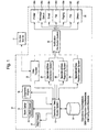
- FIG 1 is a schematic of the central site system 10 according to a preferred embodiment of the invention, where the central site system 10 is in communication with a remote site equipment monitor 11.
- the central site system 10 is shown within the dashed lines.
- the remote site equipment monitor 11 is not part of the central site system 10 in this embodiment, and is remote from the central site system 10.
- the remote site equipment monitor 11 monitors one or more pieces of equipment (not shown), such as gas turbines, jet engines, etc., at an equipment site, and collects operational data concerning the equipment.
- the remote site equipment monitor 11 interfaces either directly with the equipment being monitored or to the equipment's controller (not shown).
- the remote site equipment monitor 11 may automatically collect and store operational data.
- the operational data is data concerning the operation of the equipment, such as the speed and temperature of the equipment, and emissions data, if applicable.
- Equipment monitors are generally known in the art.
- the central site system 10 includes a data transfer system 18, which is adapted for the receiving operational data from the remote site equipment monitor 11.
- the data transfer system 18 will be connected to a number of remote site equipment monitors, and will be connected to at least one remote site equipment monitor.
- the data transfer system 18 also transfers the operational data received from the remote site equipment monitor 11 to an operational data access system 12.
- the central site system 10 also includes a number of other subsystems as shown in Figure 1. These subsystems include an operational data distribution system 20 which requests and receives operational data from the operational data access system 12 and customizes the data into at least one customized data set, an operational data reporting system 22 which requests and receives operational data from the operational data access system 12 and converts the operational data into at least one predefined informational report, and an operational data transformation system 24 which requests and receives operational data from the operational data access system 12 and transforms the operational data into transformed data according to a predefined transformation definition.
- an operational data distribution system 20 which requests and receives operational data from the operational data access system 12 and customizes the data into at least one customized data set
- an operational data reporting system 22 which requests and receives operational data from the operational data access system 12 and converts the operational data into at least one predefined informational report
- an operational data transformation system 24 which requests and receives operational data from the operational data access system 12 and transforms the operational data into transformed data according to a predefined transformation definition.
- the central site system 10 also includes a notification distribution system 26 which receives data based on the operational data and distributes the data based on the operational data to a destination according to a predefined schedule.
- the notification distribution system 26 may receive the data from any of the data transfer system 18, operational data distribution system 20, operational data reporting system 22, and operational data transformation system 24.
- the notification distribution system 26 also includes a number of modes of communication 30 for communicating with a number of different destinations.
- the modes of communication may include communication modes for a printer 30a, message queue 30b, e-mail 30c, facsimile 30d, paging system 30e, data storage file 30f and other communication modes 30g.
- the modes of communication are connected to respective communication devices (not shown) outside of the central site system 10, such as a printer, etc.
- the central site system 10 also includes a work center 14 that allows for user interaction with the central site system 10.
- the work center 14 may include a viewer 15 that displays data graphically and or numerically for a user.
- the viewer 15 may be a monitoring and diagnostics viewer (M&D viewer), for example. Alternately, the viewer 15 may be separate from the work center 14.
- M&D viewer monitoring and diagnostics viewer
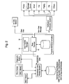
- Figure 2 illustrates the data transfer system 18, and its communication with other subsystems and the remote site equipment monitor 11. For ease of illustration, not all of the subsystems are shown in Figure 2.
- the data transfer system 18 is responsible for scheduling operational data transfer from the remote site equipment monitor 11 to the central site system 10, for initiating a connection between the remote site equipment monitor 11 and the central site system 10, and for managing data and file transfers.
- the data transfer system 18 includes a data transfer unit 40 and a data transfer manager 42.
- the data transfer unit 40 is adapted for initiating a connection with the remote site equipment monitor 11.
- the data transfer unit 40 also interfaces and communicates with the operational data access system 12 for requesting data insertion into the operational database, and to the notification distribution system 26 to provide new data messages, i.e., messages that new operational data has been received from the remote site equipment monitor 11.
- the data transfer manager 42 provides for the transfer of the operational data from the remote site equipment monitor 11 according to a data transfer schedule.
- the data transfer manager 42 may include its own database system to manage the transfer schedule.
- the transfer schedule may include, for example, a list of operational data elements, a sample transfer rate, a time interval between data transfers, a time for a next data transfer, and other associated data.
- the data transfer manager 42 is responsible for scheduling the transfer.
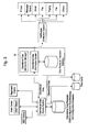
- Figure 3 illustrates the operational data distribution system 20, and its communication with other subsystems. For ease of illustration, not all of the subsystems are shown in Figure 3.
- the operational data distribution system 20 is responsible for managing customized data sets. These data sets may be stored in data marts, for example, which can reside on a local database server or may be distributed to multiple database servers.
- the operational data distribution system 20 requests and receives operational data from the operational data access system 12 and customizes the data into at least one customized data set.
- the operational data distribution manager 20 is responsible for scheduling the distribution of the customized data sets. This system interfaces to the operational data access system 12 for requesting operational data and for inserting data into the appropriate data marts.
- the operational data distribution system 20 transfers the at least one customized data set to the notification distribution system 26 according to an operational data distribution schedule.
- the notification distribution system 26 then transfers the at least one customized data set to an appropriate destination according to the operational data distribution schedule.
- the operational data distribution system 20 may employ its own database system to manage the extraction and distribution of customized data sets.
- a customized data set could be for an equipment site with an equipment monitor 11 including sensors for monitoring vibration of gas turbine equipment. This data set could then be distributed to the appropriate destination of a workstation or engineer via the notification distribution system 26.
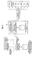
- Figure 4 illustrates an operational data reporting system 22, and its communication with other subsystems. For ease of illustration, not all of the subsystems are shown in Figure 4.
- the operational data reporting system 22 converts operational data into predefined informational reports according to a specified schedule. These reports can include textual as well as graphical information.
- the operational data reporting system 22 manages the report definitions and schedules in a database system.
- the operational data reporting manager 22 determines which report to process and when.
- the operational data reporting manager 22 interfaces to the operational data access system 12 for data requests and notifies the notification distribution system 26 with a report message.
- the operational data reporting system 22 requests and receives operational data from the operational data access system 12 and converts the operational data into at least one predefined informational report.
- the operational data reporting system 22 transfers the at least one predefined informational report to the notification distribution system 26 according to an informational report distribution schedule.
- the notification distribution system 26 transfers the at least one predefined informational report to an appropriate destination according to the predefined informational report distribution schedule.
- Figure 5 illustrates an operational data transformation system 24, and its communication with other subsystems. For ease of illustration, not all of the subsystems are shown in Figure 5.
- the operational data transformation system 24 transforms the operational data into a more useful form. Transforming the data refers to applying some type of algorithm to the data. For example, high pass filtering, low pass filtering and weighted averaging may be applied to the data.
- the operational data transformation system 24 can also perform calculations on the data and generate result sets.
- This system has a manager for scheduling transformations and has a local database for storing transformation definitions and schedules.
- the operational data transformation system 24 communicates with the operational data access system 12 for retrieving and storing data. Upon completion of any transformation, a message may sent to the notification distribution system 26 for distribution.
- the operational data transformation system 24 requests and receives operational data from the operational data access system 12 and transforms the operational data into transformed data according to a predefined transformation definition.
- the operational data transformation system 24 transfers the transformed data to the notification distribution system 26 according to a transformed data distribution schedule.
- the notification distribution system 26 transfers the transformed data to an appropriate destination according to the transformed data distribution schedule.
- FIG. 6 illustrates the notification distribution system 26, and its communication with other subsystems.
- the notification distribution system 26 provides a general service available to any other service for distributing information.
- the notification distribution system 26 supports multiple modes of communication 30 including modes for printers 30a, message queues 30b, e-mails 30c, faxes 30d, paging 30e, files 30f, and others 30g.
- the notification distribution system 26 system has a manager for managing the scheduling and the distribution of information and also a data storage for containing distribution rules.
- the manager of the notification distribution system 26 may also provide a user interface for creating, modifying, and deleting the rules.
- the communication can be asynchronous or synchronous.
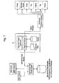
- Figure 7 illustrates the diagnostic engine 16, and its communication with other subsystems. For ease of illustration, not all of the subsystems are shown in Figure 7.
- the diagnostic engine 16 communicates with and receives operational data from the operational data access system 12, and provides an indication of the operation of equipment monitored by the at least one equipment monitor based upon an analysis of the received operational data.
- the indication of the operation may be, for example, equipment failure, or a reduced performance of the equipment.
- the diagnostic engine 16 includes applications that process the operational data, determine or identify anomalies, and generate calculations and results.
- the diagnostic engine 16 typically contains rule-based or model-based algorithms that when applied to the operational data may predict the health of the equipment being monitored.
- the models or algorithms and initialization files for initializing the knowledge base may be included in a database of the diagnostic engine 16.
- the initializing information may be used along with the operational data in diagnosing equipment.
- a system user may request the appropriate operational data to be used in the analysis and may initiate the diagnostic engine, or this may be performed automatically.
- the diagnostic engine system 16 interfaces with the operational data access system 12 for data retrieval insertion and communicates with the notification distribution system 26 with alerts and other report type messages.
- the operational data access system 12 may provide secured and transparent access to the central site data storage unit 13 of the operational data access system 12 via the work center 14.
- the operational data access system 12 may also provide a common interface for client applications, and accommodate multiple data collection strategies and multiple data reduction strategies via the work center 14.
- the work center 14 may include a Web browser and integration software for hosting a collection of cooperating applications that support the functions and activities of the central site 10.
- the work center 14 allows for user interaction with the operational data access system through any one of a plurality of user applications.
- the work center 14 facilitates the sharing of information between applications; thus, improving the productivity and efficiency of service delivery.
- Applications include, for example equipment health monitoring, electronic notebook, equipment diagnostics, equipment problem escalation, equipment prognostics, and record and journal keeping.
- Management applications may also be hosted by the work center 14 and may include scheduling of monitoring of equipment and personnel, work load balancing, and service contract compliance. Possible administrative applications could support time management and session management.
- the viewer 15 provides for displaying data graphically and numerically, allows for defining plots and data sets, and interfaces with the operational data access system 12 for retrieving of data.
- the user can specify filters for reducing the amount of data in the requested result sets.
- Plots can be exported in various formats for including in reports.
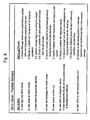
- Figure 8 illustrates a possible scenario for a user at the work center 14.
- the user begins by logging onto the work center 14.
- the user then may choose a desired application.
- the user first chooses to run a health review application to review the health of some remotely monitored equipment.
- the user may then see information on a display concerning the health of the identified piece of equipment. The user than acknowledges the health review.
- the user may choose to run another application, and thus selects another unit, and clicks on a diagnostic results application to the start the application.
- the user can then review the diagnostic results for the earlier identified piece of equipment on the display, and store comments and finding in an electronic notebook application, for example.
- the user may then choose to initiate a call tracking application to keep track of his findings.
- the user can continue to use a number of applications from the work center 14, as desired.
Landscapes
- Physics & Mathematics (AREA)
- General Physics & Mathematics (AREA)
- Engineering & Computer Science (AREA)
- Computer Networks & Wireless Communication (AREA)
- Testing And Monitoring For Control Systems (AREA)
- Selective Calling Equipment (AREA)
- Management, Administration, Business Operations System, And Electronic Commerce (AREA)
Abstract
Description
- This invention is related generally to a system architecture for remotely monitoring equipment and providing diagnostic, prognostic, and other information for the equipment.
- The performance of heavy industrial equipment, such as gas turbines, jet engines, industrial motors, locomotives, etc., will tend to decline over time, and ultimately failure occurs. When the equipment's performance declines to an unacceptable level, and the equipment customer is aware of the unacceptable level, the customer may call an equipment service provider to perform necessary maintenance or repairs as per a service contract between the equipment customer and the equipment service provider. The service provider may also periodically provide maintenance on the equipment as per the contract without receiving a call from the equipment customer.
- In accordance with one aspect of the present invention, there is provided central site system for communicating with at least one remote site equipment monitor, the at least one remote site equipment monitor collecting operational data concerning remote site equipment. The central site system comprises: a data transfer system adapted for receiving the operational data from the at least one remote site equipment monitor; an operational data access system which receives the operational data from the data transfer system and stores the operational data in a data storage unit of the operational data access system; and a notification distribution system which receives data based on the operational data and distributes the data based on the operational data to a destination according to a predefined schedule.
- In accordance with another aspect of the present invention, there is provided a central site system for communicating with at least one remote site equipment monitor, the at least one remote site equipment monitor collecting operational data concerning remote site equipment. The central site system comprises: a data transfer system adapted for receiving the operational data from the at least one remote site equipment monitor; an operational data access system which receives the operational data from the data transfer system and stores the operational data in a data storage unit of the operational data access system; and a diagnostic engine communicating with and receiving operational data from the operational data access system, and providing an indication of the operation of equipment monitored by the at least one equipment monitor based upon an analysis of the received operational data.
- Embodiments of the invention will now be described, by way of example, with reference to the accompanying drawings, in which:
- Figure 1 is a schematic of a central site system according to a preferred embodiment of the invention.
- Figure 2 is a schematic of the central site system according to a preferred embodiment of the invention illustrating the data transfer system in greater detail.
- Figure 3 is a schematic of the central site system according to a preferred embodiment of the invention illustrating the operational data distribution system in greater detail.
- Figure 4 is a schematic of the central site system according to a preferred embodiment of the invention illustrating the operational data reporting system in greater detail.
- Figure 5 is a schematic of the central site system according to a preferred embodiment of the invention illustrating the operational data transformation system in greater detail.
- Figure 6 is a schematic of the central site system according to a preferred embodiment of the invention illustrating the notification distribution system in greater detail.
- Figure 7 is a schematic of the central site system according to a preferred embodiment of the invention illustrating the diagnostic engine in greater detail.
- Figure 8 is a Figure illustrating a possible scenario at the Work Center.
-
- Reference will now be made in detail to presently preferred embodiments of the present invention. Wherever possible, the same reference numbers will be used throughout the drawings to refer to the same or like parts.
- The present inventors have realized that there is a need for a system architecture that allows for the collection of equipment operational data at an equipment site, and then transferring of that operation data to a central site remote from the equipment site for performance of diagnostics concerning the equipment. An equipment service provider using the system architecture would be able to manage the operational data to achieve several benefits and provide improved equipment. For example, the service provider could make an informed decision about when and whether or not to make a service call to repair, replace, or maintain the remote equipment based upon the collection of data stored at the central site concerning the health or status of the equipment.
- Furthermore, other information relative to the remote equipment which is important to the service provider and customer can be correlated at the central site, and distributed to an appropriate destination. For example, insurance data concerning the equipment would be available at the central site, and would aid in allowing a service provider to make an informed decision on what action to take based on the current monitored status of the equipment. For equipment subject to regulations, such as emissions regulations, data on the equipment emissions and regulations might be stored at the central site, and a service provider or customer could be informed of the equipment failing its emission standard, and appropriate action can then be taken.
- The information infrastructure provided by the central site data storage and diagnostics integrated with the remote site operational data collection allows for flexibility. This integrated system may provide access to equipment operational data, access to the equipment's configuration information, the transformation and distribution of operational data, notification of events such as equipment failure, generation of reports and messages, and the integration of Web based and client based tools for visualization, diagnostics and other applications.
- Figure 1 is a schematic of the
central site system 10 according to a preferred embodiment of the invention, where thecentral site system 10 is in communication with a remotesite equipment monitor 11. Thecentral site system 10 is shown within the dashed lines. The remotesite equipment monitor 11 is not part of thecentral site system 10 in this embodiment, and is remote from thecentral site system 10. The remote site equipment monitor 11 monitors one or more pieces of equipment (not shown), such as gas turbines, jet engines, etc., at an equipment site, and collects operational data concerning the equipment. The remote site equipment monitor 11 interfaces either directly with the equipment being monitored or to the equipment's controller (not shown). The remotesite equipment monitor 11 may automatically collect and store operational data. The operational data is data concerning the operation of the equipment, such as the speed and temperature of the equipment, and emissions data, if applicable. Equipment monitors are generally known in the art. - The
central site system 10 includes adata transfer system 18, which is adapted for the receiving operational data from the remotesite equipment monitor 11. In general, thedata transfer system 18 will be connected to a number of remote site equipment monitors, and will be connected to at least one remote site equipment monitor. Thedata transfer system 18 also transfers the operational data received from the remotesite equipment monitor 11 to an operationaldata access system 12. - The
central site system 10 also includes a number of other subsystems as shown in Figure 1. These subsystems include an operationaldata distribution system 20 which requests and receives operational data from the operationaldata access system 12 and customizes the data into at least one customized data set, an operationaldata reporting system 22 which requests and receives operational data from the operationaldata access system 12 and converts the operational data into at least one predefined informational report, and an operationaldata transformation system 24 which requests and receives operational data from the operationaldata access system 12 and transforms the operational data into transformed data according to a predefined transformation definition. - The
central site system 10 also includes anotification distribution system 26 which receives data based on the operational data and distributes the data based on the operational data to a destination according to a predefined schedule. Thenotification distribution system 26 may receive the data from any of thedata transfer system 18, operationaldata distribution system 20, operationaldata reporting system 22, and operationaldata transformation system 24. Thenotification distribution system 26 also includes a number of modes ofcommunication 30 for communicating with a number of different destinations. The modes of communication may include communication modes for aprinter 30a,message queue 30b,e-mail 30c, facsimile 30d,paging system 30e,data storage file 30f andother communication modes 30g. The modes of communication are connected to respective communication devices (not shown) outside of thecentral site system 10, such as a printer, etc. - The
central site system 10 also includes awork center 14 that allows for user interaction with thecentral site system 10. Thework center 14 may include aviewer 15 that displays data graphically and or numerically for a user. Theviewer 15 may be a monitoring and diagnostics viewer (M&D viewer), for example. Alternately, theviewer 15 may be separate from thework center 14. - The subsystems of the
central site system 10 are now described in more detail below. - Figure 2 illustrates the
data transfer system 18, and its communication with other subsystems and the remotesite equipment monitor 11. For ease of illustration, not all of the subsystems are shown in Figure 2. Thedata transfer system 18 is responsible for scheduling operational data transfer from the remotesite equipment monitor 11 to thecentral site system 10, for initiating a connection between the remotesite equipment monitor 11 and thecentral site system 10, and for managing data and file transfers. - The
data transfer system 18 includes adata transfer unit 40 and adata transfer manager 42. Thedata transfer unit 40 is adapted for initiating a connection with the remotesite equipment monitor 11. Thedata transfer unit 40 also interfaces and communicates with the operationaldata access system 12 for requesting data insertion into the operational database, and to thenotification distribution system 26 to provide new data messages, i.e., messages that new operational data has been received from the remotesite equipment monitor 11. - The
data transfer manager 42 provides for the transfer of the operational data from the remotesite equipment monitor 11 according to a data transfer schedule. Thedata transfer manager 42 may include its own database system to manage the transfer schedule. The transfer schedule may include, for example, a list of operational data elements, a sample transfer rate, a time interval between data transfers, a time for a next data transfer, and other associated data. Thedata transfer manager 42 is responsible for scheduling the transfer. - Figure 3 illustrates the operational
data distribution system 20, and its communication with other subsystems. For ease of illustration, not all of the subsystems are shown in Figure 3. The operationaldata distribution system 20 is responsible for managing customized data sets. These data sets may be stored in data marts, for example, which can reside on a local database server or may be distributed to multiple database servers. - The operational
data distribution system 20 requests and receives operational data from the operationaldata access system 12 and customizes the data into at least one customized data set. The operationaldata distribution manager 20 is responsible for scheduling the distribution of the customized data sets. This system interfaces to the operationaldata access system 12 for requesting operational data and for inserting data into the appropriate data marts. The operationaldata distribution system 20 transfers the at least one customized data set to thenotification distribution system 26 according to an operational data distribution schedule. Thenotification distribution system 26 then transfers the at least one customized data set to an appropriate destination according to the operational data distribution schedule. - The operational
data distribution system 20 may employ its own database system to manage the extraction and distribution of customized data sets. For example, a customized data set could be for an equipment site with anequipment monitor 11 including sensors for monitoring vibration of gas turbine equipment. This data set could then be distributed to the appropriate destination of a workstation or engineer via thenotification distribution system 26. - Figure 4 illustrates an operational
data reporting system 22, and its communication with other subsystems. For ease of illustration, not all of the subsystems are shown in Figure 4. The operationaldata reporting system 22 converts operational data into predefined informational reports according to a specified schedule. These reports can include textual as well as graphical information. The operationaldata reporting system 22 manages the report definitions and schedules in a database system. The operationaldata reporting manager 22 determines which report to process and when. The operationaldata reporting manager 22 interfaces to the operationaldata access system 12 for data requests and notifies thenotification distribution system 26 with a report message. - The operational
data reporting system 22 requests and receives operational data from the operationaldata access system 12 and converts the operational data into at least one predefined informational report. The operationaldata reporting system 22 transfers the at least one predefined informational report to thenotification distribution system 26 according to an informational report distribution schedule. Thenotification distribution system 26 transfers the at least one predefined informational report to an appropriate destination according to the predefined informational report distribution schedule. - Figure 5 illustrates an operational
data transformation system 24, and its communication with other subsystems. For ease of illustration, not all of the subsystems are shown in Figure 5. The operationaldata transformation system 24 transforms the operational data into a more useful form. Transforming the data refers to applying some type of algorithm to the data. For example, high pass filtering, low pass filtering and weighted averaging may be applied to the data. The operationaldata transformation system 24 can also perform calculations on the data and generate result sets. This system has a manager for scheduling transformations and has a local database for storing transformation definitions and schedules. The operationaldata transformation system 24 communicates with the operationaldata access system 12 for retrieving and storing data. Upon completion of any transformation, a message may sent to thenotification distribution system 26 for distribution. - The operational
data transformation system 24 requests and receives operational data from the operationaldata access system 12 and transforms the operational data into transformed data according to a predefined transformation definition. The operationaldata transformation system 24 transfers the transformed data to thenotification distribution system 26 according to a transformed data distribution schedule. Thenotification distribution system 26 transfers the transformed data to an appropriate destination according to the transformed data distribution schedule. - Figure 6 illustrates the
notification distribution system 26, and its communication with other subsystems. Thenotification distribution system 26 provides a general service available to any other service for distributing information. Thenotification distribution system 26 supports multiple modes ofcommunication 30 including modes forprinters 30a,message queues 30b,e-mails 30c,faxes 30d,paging 30e,files 30f, andothers 30g. Thenotification distribution system 26 system has a manager for managing the scheduling and the distribution of information and also a data storage for containing distribution rules. The manager of thenotification distribution system 26 may also provide a user interface for creating, modifying, and deleting the rules. The communication can be asynchronous or synchronous. - Figure 7 illustrates the
diagnostic engine 16, and its communication with other subsystems. For ease of illustration, not all of the subsystems are shown in Figure 7. Thediagnostic engine 16 communicates with and receives operational data from the operationaldata access system 12, and provides an indication of the operation of equipment monitored by the at least one equipment monitor based upon an analysis of the received operational data. The indication of the operation may be, for example, equipment failure, or a reduced performance of the equipment. - The
diagnostic engine 16 includes applications that process the operational data, determine or identify anomalies, and generate calculations and results. Thediagnostic engine 16 typically contains rule-based or model-based algorithms that when applied to the operational data may predict the health of the equipment being monitored. The models or algorithms and initialization files for initializing the knowledge base may be included in a database of thediagnostic engine 16. The initializing information may be used along with the operational data in diagnosing equipment. A system user may request the appropriate operational data to be used in the analysis and may initiate the diagnostic engine, or this may be performed automatically. Thediagnostic engine system 16 interfaces with the operationaldata access system 12 for data retrieval insertion and communicates with thenotification distribution system 26 with alerts and other report type messages. - Returning to Figure 1, the operational
data access system 12,work center 14 andviewer 15 are now further described. The operationaldata access system 12 may provide secured and transparent access to the central sitedata storage unit 13 of the operationaldata access system 12 via thework center 14. The operationaldata access system 12 may also provide a common interface for client applications, and accommodate multiple data collection strategies and multiple data reduction strategies via thework center 14. - The
work center 14 may include a Web browser and integration software for hosting a collection of cooperating applications that support the functions and activities of thecentral site 10. Thework center 14 allows for user interaction with the operational data access system through any one of a plurality of user applications. Thework center 14 facilitates the sharing of information between applications; thus, improving the productivity and efficiency of service delivery. Applications include, for example equipment health monitoring, electronic notebook, equipment diagnostics, equipment problem escalation, equipment prognostics, and record and journal keeping. Management applications may also be hosted by thework center 14 and may include scheduling of monitoring of equipment and personnel, work load balancing, and service contract compliance. Possible administrative applications could support time management and session management. - The
viewer 15 provides for displaying data graphically and numerically, allows for defining plots and data sets, and interfaces with the operationaldata access system 12 for retrieving of data. The user can specify filters for reducing the amount of data in the requested result sets. Plots can be exported in various formats for including in reports. - Figure 8 illustrates a possible scenario for a user at the
work center 14. The user begins by logging onto thework center 14. The user then may choose a desired application. In this scenario, the user first chooses to run a health review application to review the health of some remotely monitored equipment. The user clicks on the health review application to start the application, and enters an appropriated equipment identifier. The user may then see information on a display concerning the health of the identified piece of equipment. The user than acknowledges the health review. - The user may choose to run another application, and thus selects another unit, and clicks on a diagnostic results application to the start the application. The user can then review the diagnostic results for the earlier identified piece of equipment on the display, and store comments and finding in an electronic notebook application, for example. The user may then choose to initiate a call tracking application to keep track of his findings. The user can continue to use a number of applications from the
work center 14, as desired.
Claims (10)
- A central site system (10) for communicating with at least one remote site equipment monitor (11), the at least one remote site equipment monitor (11) collecting operational data concerning remote site equipment, the central site system comprising:a data transfer system (18) adapted for receiving the operational data from the at least one remote site equipment monitor (11);an operational data access system (12) which receives the operational data from the data transfer system (18) and stores the operational data in a data storage unit (13) of the operational data access system (12); anda notification distribution system (26) which receives data based on the operational data and distributes the data based on the operational data to a destination according to a predefined schedule.
- The central site system (10) of claim 1, wherein the data transfer system (18) further comprises:a data transfer unit (40) adapted for initiating a connection with one of the at least one remote site equipment monitors (11).
- The central site system (10) of claim 1, further comprising:an operational data distribution system (20) which requests and receives operational data from the operational data access system (12) and customizes the data into at least one customized data set.
- The central site system (10) of claim 1, further comprising:an operational data transformation system (24) which requests and receives operational data from the operational data access system (12) and transforms the operational data into transformed data according to a predefined transformation definition.
- The central site system (10) of claim 1, wherein the notification distribution system (26) comprises a user interface which allows a user to modify the predefined schedule.
- The central site system (10) of claim 1, further comprising:a diagnostic engine (16) communicating with and receiving operational data from the operational data access system (12), and providing an indication of the operation of equipment monitored by the at least one equipment monitor (11) based upon an analysis of the received operational data.
- The central site system (10) of claim 6, wherein the diagnostic engine (16) provides the indication of the operation of the equipment based an algorithm stored in the diagnostic engine.
- The central site system (10) of claim 6, wherein the diagnostic engine (16) provides the indication of the operation of the equipment based on information from initialization files stored in the diagnostic engine (16), wherein the initialization files provide information regarding the initial condition of the equipment.
- The central site system (10) of claim 1, wherein the data storage unit (13) of the operational data access system (12) stores in addition to operational data, other data concerning equipment monitored by the least one remote site monitor (11).
- A central site system (10) for communicating with at least one remote site equipment monitor (11), the at least one remote site equipment monitor (11) collecting operational data concerning remote site equipment, the central site system comprising:a data transfer system (18) adapted for receiving the operational data from the at least one remote site equipment monitor (11);an operational data access system (12) which receives the operational data from the data transfer system (18) and stores the operational data in a data storage unit (13) of the operational data access system (12); anda diagnostic engine (16) communicating with and receiving operational data from the operational data access system (12), and providing an indication of the operation of equipment monitored by the at least one equipment monitor (11) based upon an analysis of the received operational data.
Applications Claiming Priority (2)
| Application Number | Priority Date | Filing Date | Title |
|---|---|---|---|
| US248157 | 2002-12-20 | ||
| US10/248,157 US7184844B2 (en) | 2002-12-20 | 2002-12-20 | Central site architecture for remote service delivery |
Publications (2)
| Publication Number | Publication Date |
|---|---|
| EP1432273A2 true EP1432273A2 (en) | 2004-06-23 |
| EP1432273A3 EP1432273A3 (en) | 2008-01-16 |
Family
ID=32392320
Family Applications (1)
| Application Number | Title | Priority Date | Filing Date |
|---|---|---|---|
| EP03257928A Withdrawn EP1432273A3 (en) | 2002-12-20 | 2003-12-16 | System architecture for remote monitoring equipments |
Country Status (3)
| Country | Link |
|---|---|
| US (1) | US7184844B2 (en) |
| EP (1) | EP1432273A3 (en) |
| JP (1) | JP4478444B2 (en) |
Cited By (4)
| Publication number | Priority date | Publication date | Assignee | Title |
|---|---|---|---|---|
| US7184844B2 (en) * | 2002-12-20 | 2007-02-27 | General Electric Company | Central site architecture for remote service delivery |
| CN100458858C (en) * | 2006-03-30 | 2009-02-04 | 纬创资通股份有限公司 | Remote monitoring method and system with active warning capability |
| CN101627629A (en) * | 2007-03-08 | 2010-01-13 | 汤姆森特许公司 | Method, apparatus and system for coordinated content distribution workflow |
| CN101057464B (en) * | 2004-09-14 | 2011-10-19 | 日本电气株式会社 | Data distribution system, and data distribution method |
Families Citing this family (17)
| Publication number | Priority date | Publication date | Assignee | Title |
|---|---|---|---|---|
| JP2002300308A (en) * | 2001-03-30 | 2002-10-11 | Ricoh Co Ltd | Customer support system, office system, customer support center, supply center, and customer support method |
| US20090089247A1 (en) * | 2007-09-28 | 2009-04-02 | Terrence Lynn Blevins | Methods and apparatus to standardize data properties in a process control environment |
| US9306877B2 (en) * | 2008-10-09 | 2016-04-05 | Thomas And Sons, Inc. | Notification system |
| US8886746B2 (en) * | 2009-09-09 | 2014-11-11 | Rockwell Automation Technologies, Inc. | Diagnostic module for distributed industrial network including industrial control devices |
| KR101866270B1 (en) * | 2011-02-21 | 2018-07-05 | 삼성전자주식회사 | Data sharing system and method thereof |
| CN104481702A (en) * | 2014-10-15 | 2015-04-01 | 哈尔滨东安发动机(集团)有限公司 | A monitoring method of micro gas turbine operation states |
| US10116563B1 (en) | 2014-10-30 | 2018-10-30 | Pearson Education, Inc. | System and method for automatically updating data packet metadata |
| US10218630B2 (en) | 2014-10-30 | 2019-02-26 | Pearson Education, Inc. | System and method for increasing data transmission rates through a content distribution network |
| US10735402B1 (en) | 2014-10-30 | 2020-08-04 | Pearson Education, Inc. | Systems and method for automated data packet selection and delivery |
| US10027740B2 (en) * | 2014-10-31 | 2018-07-17 | Pearson Education, Inc. | System and method for increasing data transmission rates through a content distribution network with customized aggregations |
| US10110486B1 (en) | 2014-10-30 | 2018-10-23 | Pearson Education, Inc. | Automatic determination of initial content difficulty |
| US10318499B2 (en) | 2014-10-30 | 2019-06-11 | Pearson Education, Inc. | Content database generation |
| US10333857B1 (en) | 2014-10-30 | 2019-06-25 | Pearson Education, Inc. | Systems and methods for data packet metadata stabilization |
| CN104574219A (en) * | 2015-01-28 | 2015-04-29 | 华东电网有限公司 | System and method for monitoring and early warning of operation conditions of power grid service information system |
| AU2017257501A1 (en) * | 2016-04-25 | 2018-11-15 | Intertrust Technologies Corporation | Data management systems and methods |
| CN106354118B (en) * | 2016-08-25 | 2019-08-09 | 株洲中车时代电气股份有限公司 | A kind of train fault diagnostic system and method based on fault tree |
| JP7460233B2 (en) * | 2018-09-28 | 2024-04-02 | 日本電気株式会社 | Information processing device, information processing method, program, and data structure |
Family Cites Families (25)
| Publication number | Priority date | Publication date | Assignee | Title |
|---|---|---|---|---|
| US656510A (en) * | 1899-05-13 | 1900-08-21 | Clarence Livingston Burger | Igniting device for gas-burners. |
| JP2758976B2 (en) * | 1990-06-07 | 1998-05-28 | 株式会社日立製作所 | Characteristic change prediction method and system |
| JPH06186140A (en) * | 1992-03-18 | 1994-07-08 | Tokyo Electric Power Co Inc:The | Plant facility diagnosis device |
| JPH06187323A (en) * | 1992-04-16 | 1994-07-08 | Tokyo Electric Power Co Inc:The | Plant facility diagnostic device |
| FR2716286A1 (en) * | 1994-02-16 | 1995-08-18 | Debiotech Sa | Installation of remote monitoring of controllable equipment. |
| NO941202L (en) * | 1994-03-30 | 1995-10-02 | Oeystein Konsmo | Method of monitoring and generating messages as well as equipment using the method |
| JPH113113A (en) * | 1997-06-10 | 1999-01-06 | Ishikawajima Harima Heavy Ind Co Ltd | Device degradation diagnosis method and device |
| US5986574A (en) * | 1997-10-16 | 1999-11-16 | Peco Energy Company | System and method for communication between remote locations |
| US7181501B2 (en) * | 1998-03-19 | 2007-02-20 | Isochron, Inc. | Remote data acquisition, transmission and analysis system including handheld wireless equipment |
| US6546553B1 (en) * | 1998-10-02 | 2003-04-08 | Microsoft Corporation | Service installation on a base function and provision of a pass function with a service-free base function semantic |
| JP2000137623A (en) * | 1998-10-30 | 2000-05-16 | Fujitsu Ltd | Diagnostic method and diagnostic system |
| US6408278B1 (en) * | 1998-11-10 | 2002-06-18 | I-Open.Com, Llc | System and method for delivering out-of-home programming |
| US6564104B2 (en) * | 1999-12-24 | 2003-05-13 | Medtronic, Inc. | Dynamic bandwidth monitor and adjuster for remote communications with a medical device |
| US6934862B2 (en) * | 2000-01-07 | 2005-08-23 | Robertshaw Controls Company | Appliance retrofit monitoring device with a memory storing an electronic signature |
| JP2001195117A (en) * | 2000-01-13 | 2001-07-19 | Toshiba Corp | Process data transmission device |
| JP2001236115A (en) * | 2000-02-24 | 2001-08-31 | Fanuc Ltd | Remote diagnostic system and method |
| US6565510B1 (en) | 2000-03-22 | 2003-05-20 | General Electric Company | Method and apparatus for servicing remote ultrasound beamformer from central service facility |
| US6580916B1 (en) * | 2000-09-15 | 2003-06-17 | Motorola, Inc. | Service framework for evaluating remote services based upon transport characteristics |
| JP2002095069A (en) * | 2000-09-20 | 2002-03-29 | Nikko Co Ltd | Plant remote maintenance management system |
| JP3691371B2 (en) * | 2000-09-22 | 2005-09-07 | 株式会社日立製作所 | Method for judging cleaning time of semiconductor manufacturing equipment |
| JP2002123879A (en) * | 2000-10-16 | 2002-04-26 | Tietech Co Ltd | Reporting method for manhole pump monitoring device |
| JP2002207513A (en) * | 2001-01-11 | 2002-07-26 | Yamatake Sangyo Systems Co Ltd | Plant monitoring equipment |
| US6795798B2 (en) * | 2001-03-01 | 2004-09-21 | Fisher-Rosemount Systems, Inc. | Remote analysis of process control plant data |
| JP4254988B2 (en) * | 2001-03-16 | 2009-04-15 | 株式会社日立製作所 | Security diagnostic system and security diagnostic method |
| US7184844B2 (en) * | 2002-12-20 | 2007-02-27 | General Electric Company | Central site architecture for remote service delivery |
-
2002
- 2002-12-20 US US10/248,157 patent/US7184844B2/en not_active Expired - Lifetime
-
2003
- 2003-12-16 EP EP03257928A patent/EP1432273A3/en not_active Withdrawn
- 2003-12-19 JP JP2003421875A patent/JP4478444B2/en not_active Expired - Fee Related
Non-Patent Citations (1)
| Title |
|---|
| None |
Cited By (4)
| Publication number | Priority date | Publication date | Assignee | Title |
|---|---|---|---|---|
| US7184844B2 (en) * | 2002-12-20 | 2007-02-27 | General Electric Company | Central site architecture for remote service delivery |
| CN101057464B (en) * | 2004-09-14 | 2011-10-19 | 日本电气株式会社 | Data distribution system, and data distribution method |
| CN100458858C (en) * | 2006-03-30 | 2009-02-04 | 纬创资通股份有限公司 | Remote monitoring method and system with active warning capability |
| CN101627629A (en) * | 2007-03-08 | 2010-01-13 | 汤姆森特许公司 | Method, apparatus and system for coordinated content distribution workflow |
Also Published As
| Publication number | Publication date |
|---|---|
| JP4478444B2 (en) | 2010-06-09 |
| JP2004206713A (en) | 2004-07-22 |
| US20040122921A1 (en) | 2004-06-24 |
| EP1432273A3 (en) | 2008-01-16 |
| US7184844B2 (en) | 2007-02-27 |
Similar Documents
| Publication | Publication Date | Title |
|---|---|---|
| US7184844B2 (en) | Central site architecture for remote service delivery | |
| US20190235485A1 (en) | Remote diagnostic systems and methods for predictive maintenance programs | |
| US6263265B1 (en) | Web information vault | |
| US20020198997A1 (en) | System and method for on board maintenance instructions and records | |
| US7177821B2 (en) | Maintenance information management system and method of providing a maintenance plan | |
| US8594304B2 (en) | Systems and methods for hybrid delivery of remote and local technical support via a centralized service | |
| US20060149808A1 (en) | Automated remote monitoring and diagnostics service method and system | |
| KR20040029387A (en) | Remote maintenance system and stock management system | |
| JP2000259729A (en) | Work machine management system | |
| EP1953692A1 (en) | Replacement part order processing apparatus, method for ordering replacement parts and computer-readable recording medium | |
| EP2622550A1 (en) | Automated printer's dashboard | |
| US6604061B2 (en) | Instruments management system and method and monitoring apparatus, database apparatus and data base client apparatuses and recording medium | |
| US20080222286A1 (en) | Computer Usage Monitoring | |
| US7287073B2 (en) | Remote site managing system for centrally managing computers and peripheral devices | |
| WO2008027128A2 (en) | Equipment management system | |
| US20040249691A1 (en) | Method, system and computer product for strategic priority order tracking | |
| JP5060752B2 (en) | Schedule management system and schedule management method | |
| JP4025000B2 (en) | Remote management system, remote management method, central management apparatus and recording medium used therefor | |
| EP2463812A1 (en) | Scheduling the maintenance of operational equipment | |
| JP4542071B2 (en) | Remote monitoring system, remote monitoring device, and remote monitoring method | |
| EP1674988A2 (en) | A monitor for an information technology system | |
| JP4108433B2 (en) | Fault recovery parts arrangement system, fault recovery parts arrangement method, fault recovery parts arrangement program | |
| JP2003187011A (en) | Vehicle inspection information providing method and vehicle inspection information providing system | |
| CN118195573A (en) | Standard operation program generation method, device, medium and equipment for intelligent maintenance system of charging equipment | |
| JP2000222316A (en) | Tool execution management method and integrated operation management system |
Legal Events
| Date | Code | Title | Description |
|---|---|---|---|
| PUAI | Public reference made under article 153(3) epc to a published international application that has entered the european phase |
Free format text: ORIGINAL CODE: 0009012 |
|
| AK | Designated contracting states |
Kind code of ref document: A2 Designated state(s): AT BE BG CH CY CZ DE DK EE ES FI FR GB GR HU IE IT LI LU MC NL PT RO SE SI SK TR |
|
| AX | Request for extension of the european patent |
Extension state: AL LT LV MK |
|
| RIC1 | Information provided on ipc code assigned before grant |
Ipc: G07C 5/00 20060101ALI20070918BHEP Ipc: H04Q 9/00 20060101AFI20040420BHEP |
|
| PUAL | Search report despatched |
Free format text: ORIGINAL CODE: 0009013 |
|
| AK | Designated contracting states |
Kind code of ref document: A3 Designated state(s): AT BE BG CH CY CZ DE DK EE ES FI FR GB GR HU IE IT LI LU MC NL PT RO SE SI SK TR |
|
| AX | Request for extension of the european patent |
Extension state: AL LT LV MK |
|
| 17P | Request for examination filed |
Effective date: 20080716 |
|
| 17Q | First examination report despatched |
Effective date: 20080811 |
|
| AKX | Designation fees paid |
Designated state(s): DE FR GB |
|
| RIC1 | Information provided on ipc code assigned before grant |
Ipc: H04Q 9/00 20060101ALI20140325BHEP Ipc: G07C 5/00 20060101ALI20140325BHEP Ipc: G07C 5/08 20060101AFI20140325BHEP |
|
| GRAP | Despatch of communication of intention to grant a patent |
Free format text: ORIGINAL CODE: EPIDOSNIGR1 |
|
| INTG | Intention to grant announced |
Effective date: 20140527 |
|
| RAP1 | Party data changed (applicant data changed or rights of an application transferred) |
Owner name: GENERAL ELECTRIC COMPANY |
|
| STAA | Information on the status of an ep patent application or granted ep patent |
Free format text: STATUS: THE APPLICATION IS DEEMED TO BE WITHDRAWN |
|
| 18D | Application deemed to be withdrawn |
Effective date: 20140607 |