EP1432178A2 - Signaling protocol and architecture for protection rings - Google Patents
Signaling protocol and architecture for protection rings Download PDFInfo
- Publication number
- EP1432178A2 EP1432178A2 EP03027177A EP03027177A EP1432178A2 EP 1432178 A2 EP1432178 A2 EP 1432178A2 EP 03027177 A EP03027177 A EP 03027177A EP 03027177 A EP03027177 A EP 03027177A EP 1432178 A2 EP1432178 A2 EP 1432178A2
- Authority
- EP
- European Patent Office
- Prior art keywords
- client
- hello
- protection
- aps
- state
- Prior art date
- Legal status (The legal status is an assumption and is not a legal conclusion. Google has not performed a legal analysis and makes no representation as to the accuracy of the status listed.)
- Granted
Links
- 230000011664 signaling Effects 0.000 title abstract description 73
- 230000003287 optical effect Effects 0.000 claims abstract description 14
- 230000005540 biological transmission Effects 0.000 claims abstract description 6
- 238000000034 method Methods 0.000 claims description 13
- 238000012545 processing Methods 0.000 claims description 7
- 239000000835 fiber Substances 0.000 abstract description 30
- 238000004891 communication Methods 0.000 abstract description 14
- RGNPBRKPHBKNKX-UHFFFAOYSA-N hexaflumuron Chemical compound C1=C(Cl)C(OC(F)(F)C(F)F)=C(Cl)C=C1NC(=O)NC(=O)C1=C(F)C=CC=C1F RGNPBRKPHBKNKX-UHFFFAOYSA-N 0.000 abstract description 8
- 230000008859 change Effects 0.000 description 37
- 230000007704 transition Effects 0.000 description 12
- 230000004044 response Effects 0.000 description 11
- 230000009471 action Effects 0.000 description 6
- 238000010586 diagram Methods 0.000 description 6
- 230000008901 benefit Effects 0.000 description 4
- 230000006870 function Effects 0.000 description 4
- 230000004048 modification Effects 0.000 description 3
- 238000012986 modification Methods 0.000 description 3
- 239000013307 optical fiber Substances 0.000 description 3
- 230000006855 networking Effects 0.000 description 2
- 238000010200 validation analysis Methods 0.000 description 2
- 101100422872 Arabidopsis thaliana SWEET8 gene Proteins 0.000 description 1
- RYGMFSIKBFXOCR-UHFFFAOYSA-N Copper Chemical compound [Cu] RYGMFSIKBFXOCR-UHFFFAOYSA-N 0.000 description 1
- 101100118563 Saccharomyces cerevisiae (strain ATCC 204508 / S288c) RPG1 gene Proteins 0.000 description 1
- 238000006243 chemical reaction Methods 0.000 description 1
- 238000010276 construction Methods 0.000 description 1
- 229910052802 copper Inorganic materials 0.000 description 1
- 239000010949 copper Substances 0.000 description 1
- 238000001514 detection method Methods 0.000 description 1
- 230000000694 effects Effects 0.000 description 1
- 238000005516 engineering process Methods 0.000 description 1
- 230000006872 improvement Effects 0.000 description 1
- 238000003780 insertion Methods 0.000 description 1
- 230000037431 insertion Effects 0.000 description 1
- 238000012423 maintenance Methods 0.000 description 1
- 230000007257 malfunction Effects 0.000 description 1
- 230000007246 mechanism Effects 0.000 description 1
- 230000008569 process Effects 0.000 description 1
- 230000008054 signal transmission Effects 0.000 description 1
- 230000007723 transport mechanism Effects 0.000 description 1
Images



Classifications
-
- H—ELECTRICITY
- H04—ELECTRIC COMMUNICATION TECHNIQUE
- H04L—TRANSMISSION OF DIGITAL INFORMATION, e.g. TELEGRAPHIC COMMUNICATION
- H04L41/00—Arrangements for maintenance, administration or management of data switching networks, e.g. of packet switching networks
- H04L41/06—Management of faults, events, alarms or notifications
-
- H—ELECTRICITY
- H04—ELECTRIC COMMUNICATION TECHNIQUE
- H04J—MULTIPLEX COMMUNICATION
- H04J3/00—Time-division multiplex systems
- H04J3/02—Details
- H04J3/14—Monitoring arrangements
Definitions
- This invention relates in general to telecommunications and, more particularly, to protection rings.
- PSTN Public Switched Telephone Network
- data networks copper wires are being replaced with optical fibers, which are capable of carrying significantly more information.
- a single fiber may transmit information over many different channels using DWDM (dense wavelength division multiplexing) techniques.
- DWDM dense wavelength division multiplexing
- ring architectures are often used.
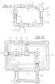
- a series of network elements are connected in a ring, such as shown in Figure 1a.
- Each ring 10 has multiple network elements 12 coupled to one another to form a closed loop.
- the working fibers (W) carry traffic between adjacent nodes.
- Protection fibers (P) are available to carry traffic in the event of a working fiber failure.
- the protection fibers also convey control information between network elements; when not being used for traffic, the protection fibers may carry low-priority interruptible traffic.
- the ring architecture shown in Figure 1a is a very simple architecture.
- multiple rings 10 may connect various network elements 12 as shown in Figure 1b.
- network elements 12 may be shared between different rings. Failures of a working fiber in any of the rings 10 may cause protect lines in multiple rings to be used.
- FIG. 2a illustrates one prior art method of circumventing a failure of a working fiber W.
- a ring 10 having five network elements 12 (referenced individually as network elements 12a-12e) has a broken working fiber W between network elements 12c and 12d.
- network elements 12c and 12d For purposes of illustration, only one working fiber W and one protection fiber P is shown, it being understood that a similar pair of working and protection fibers are used for traffic in the opposite direction.
- network element 12d connects the working lines 16de to protect lines 18cd and network element 12c connects working lines 16bc to protect lines 18cd.
- traffic that would normally be routed over working lines 16cd is switched to the associated protect lines 18cd. This is referred to as a "span" switch.
- Figure 2b illustrates a situation where both the working and protection lines have failed between network elements 12c and 12d.
- a "ring" switch is implemented where working line 16de is rerouted to protect line 18de and working line 16bc is rerouted to protect line 18bc. Accordingly, the remaining viable protect lines all carry traffic. Every network element can still communicate with all the other network elements 12 on the ring.
- the transport mechanism protocol uses K1/K2 overhead bytes transmitted "in-band", i.e., on the same channel as the associated traffic.
- K1/K2 overhead bytes transmitted "in-band", i.e., on the same channel as the associated traffic.
- transparent network elements which do not translate the data carried on the optical fibers to electronic form; instead the data traffic is switched at the network element using an optical switch. While transparent network elements have the benefit of increased speed through the switch, it is not possible to add control data to the channels. Hence, it is not possible to use the current standard K1/K2 overhead bytes.
- shared protection structures provide additional protection capabilities.
- a basic shared ring architecture is disclosed in WO 99/23773 (PCT/IB98/01955) to Elahmadi et al, where two rings share a protection path between a pair of common network elements.
- This application proposes the use of a single physical span (the shared protect line) between the common network elements to provide protection for the two rings.
- a failure on either ring can be remedied by using the shared protect line to carry traffic.
- This architecture reduces costs, which can be significant if the distance between the shared network elements is long (or there are other infrastructure costs involved), but increases the chance of a traffic outage on one ring if a failure occurs while there is another failure on another ring.
- the IETF Internet Engineering Task Force
- O-APS Optical Automatic Protection Switching protocol
- This proposal uses the OSC (optical supervision channel) of each link for passing protection signaling.
- the O-APS protocol in the IETF draft combines the functions of a signaling engine with that of a ring state machine processor.
- the protocol calls out specific protection switching procedures that are different from traditional, time-tested, switching procedures.
- the switching procedures are tightly coupled to the passing of the protection signaling data in a single protocol.
- the proposed protocol uses information similar to K-bytes for the SONET/SDH standards, the data is encoded in a completely different format.
- a network element comprises input/output circuitry for transmitting and receiving data traffic over optical links and protection state machines for receiving control information from input/output circuitry indicating transmission failures. Error messages are received from the protection state machines and error information is passed to adjacent network elements over an out-of-band network.
- Figure 1a illustrates a series of network element in a ring architecture
- Figure 1b illustrates a ring architecture with multiple overlapping rings
- Figure 2a illustrates a span switch in a ring architecture
- Figure 2b illustrates a ring switch in a ring architecture
- Figure 3 illustrates a block diagram of a pair of network elements using out-of-fiber, out-of-band (OF/OB) networking to communicate control information compatible with existing K-Byte protocols;
- OF/OB out-of-band
- Figure 4 illustrates a ring architecture capable of line shared protection ring (LSPR) protection
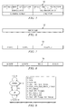
- Figure 5 illustrates a message header used on KBSP (K-Byte Signaling Protocol) messages
- Figure 6 illustrates a message body format for a NAK message
- Figure 7 illustrates a message body format for a non-NAK, non-LSPR message
- Figure 8 illustrates a message body format for a non-NAK, LSPR message
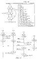
- Figure 9 illustrates a transition diagram for the KBSP client state machine of Figure 3.
- Figure 10 illustrates a transition diagram for the KBSP server state machine of the APS Signaling controller of Figure 3;
- Figure 11 illustrates a synchronization message flow
- Figure 12 illustrates an APS_Change message flow.
- Figure 3 illustrates a block diagram of a pair of network elements 20 (individually labeled as Network Element0 and Network Element1) using out-of-fiber, out-of-band (OF/OB) networking to communicate control information compatible with existing K-Byte protocols.
- network elements 20 individually labeled as Network Element0 and Network Element1
- OF/OB out-of-band
- Each network element 20 includes control communication circuitry 22 for communicating K1/K2-like control information between network elements and data communication circuitry 24 for transparently communicating data traffic.
- the control communications included OAM&P (Operations, Administration, Maintenance, and Provisioning) circuitry 26, IP Network Communication circuitry 28 and APS (Automatic Protection Switching) signalling controller 30.
- Data communication circuitry 24 includes I/O & Fault Detection circuits 32 coupled by an optical cross connect (OXC) 34.
- Optical cross connect 34 is controlled by OXC control circuitry 36.
- Protection state machines (PSM) 38 are coupled to respective I/O & Fault Detect circuits 32.
- KBSP (K-Byte Signaling Protocol) state machines 40 are coupled to respective protection state machines 38.
- the combined protection state machines 38 and associated client KBSP state machines 40 are referred to herein as the ring state machine (RSM) 41.
- the protection state machines 38 include state machines for each protection type (e.g., 1:1, 1:N, and so on) used by the network element. For each protection group, there is a separate signaling instance within the APS signaling controller 30, KBSP signaling controllers 40 and protection state machines 38.
- data traffic is passed between Network Element0 and Network Element1 on optical links 42.
- Data is passed transparently (i.e., without conversion to electronic signals) through the I/O & Fault Detect circuits 32 and optical cross connect 34 for communication to other network elements 20.
- the I/O and Fault Detect circuits 32 can detect a signal transmission fault on an incoming channel. A fault may occur on a single channel due to a laser malfunction or may occur simultaneously on multiple channels if a fiber is cut or inadvertently disconnected from a network element. At this point, a fault is sent to the associated protection state machine 38.
- the protection state machine would send messages in-band using K1/K2 signaling. In a transparent network, insertion of the K1/K2 bytes is not possible. In the network elements of Figure 3, this data is sent to the associated KBSP Client state machine 40, which passes the information to the APS Signaling controller 30.
- the APS Signaling controller 30 uses the IP Network Communication circuit to pass the control information from KBSP Client state machine to neighboring network elements 20 over an out-of--fiber, out-of-band (OF/OB) network 44.
- the OF/OB network 44 could be, for example, an IP-based network.
- the IP Network communication circuitry 28 performs common functions such as link management protocol (LMP) for establishing control sessions between nodes and associating control channels with data channels in a protect group. Further, the IP Network communication circuitry 28 includes a routing manager to efficiently route the control information.
- LMP link management protocol
- the protection state machines 38 include protection protocols that support shared protection lines.
- a single optical fiber is available for protection in two or more rings.
- Figure 4 illustrates a ring architecture capable of LSPR protection. In this figure, twelve network elements are arranged in five ring protection groups (RPGs). Certain additional information is necessary support LSPR.
- a "ring sequence" is an ordered list of nodes that defines sequence of nodes upon which RPGs are built. In Figure 4, RPG1's representation would be the ordered list NE1-NE2-NE7-NE6-NE5.
- a "local node” is the integer node number representing the local network element's node identifier for the associated ring protect group.
- a "node address list” is either an indexed list of IP addresses for each node in the ring protect group, or the IP address of the immediate east and west nodes from the local node perspective. Node addresses are required to allow for control plane communications flows.
- the IP control plane based APS signaling only requires east-west node addressing. The determination of maintaining east-west addressing or complete ring addressing may be determined based on the detailed definition of the protocol needed for ring connection map distribution.
- FTP Flust Facility Protection
- the association may define one of multiple protection constructs such as 1+1 line protection, m:n line protection, or various ring protection methods such as 4 fiber bi-directional line switched rings or line shared protection rings.
- line shared protection rings For the addition of line shared protection rings, the following data from the association is of particular interest:
- RPG data is required by the Ring State Machine 41 for state machine processing and by the APS Signaling Controller component for APS signaling message routing.
- the APS signaling controller 30 is the interface component between the ring state machine 41 and the IP Network communication circuitry 28. Each APS signaling controller 30 and protection state machines 38 communicate via the KBSP client side state machine 40. APS signaling controller 30 of different network elements communicate by a KBSP server side state machine implemented in the APS signaling controllers. The operation for the client side and server side state machines are described in detail below.
- the ring state machine 41 is the central component required for LSPR processing as it contains the core LSPR state machine algorithm.
- the ring state machine 41 is composed of two parts: (1) the protection state machine 38 that contains the protection decisions and (2) the KBSP client side state machine 40.
- the protection state machine 38 of the ring state machine for LSPR performs the following functions:
- One instance of a ring state machine 41 will exist per fast facility protection.
- K-Byte Signaling Protocol defines the out of band signaling protocol and associated state machines used to transmit K1/K2 like data between neighboring APS signaling controllers 30, and between APS signaling controllers 30 and associated ring state machines 41.
- KBSP contains the necessary additional data required for the system to perform LSPR functionality.
- KBSP is is designed to be flexible enough to support additional functionality as it is developed.
- KBSP protocol messages are encapsulated in IP packets for transmission across the control plane.
- KBSP utilizes a lightweight hello protocol for peer discovery/synchronization and to limit the bandwidth required between peers.
- Figure 5 illustrates a header used on KBSP messages.
- the header has eight fields: version number, message type, message length, protect type, source link ID, destination link ID, sequence number and checksum.
- version number indicates the version of KBSP being used for the message.
- the message type signifies what type of message is being transmitted. Currently defined message types (expressed in hexadecimal) are shown in Table 1.
- the message length field specifies the length (in bytes) of the KBSP message, including the KBSP header.
- the protect type field specifies the protection type being used. Currently defined protection types are shown in Table 2. Protection Types Value Protection Type 0x01 1_P_1_UNI - 1 + 1 Uni-directional Line Protection 0x02 1 P 1 BI - 1 + 1 Bi-directional Line Protection 0x03 M F N - M : N Bi-directional Line Protection 0x04 LSPR - Line Shared Protection Ring Protection 0x05 4FIBER_BI - 4 Fiber Bi-directional Ring Protection
- the source link ID is an unnumbered link identifier for the source node sending the KBSP message that is used to validate connectivity at run time.
- the destination link ID is an unnumbered link identifier for the destination node receiving the KBSP message that is used to route the message to the appropriate KBSP instance and RSM instance.
- the sequence number field contains an incremental KBSP message sequence number.
- the checksum field contains the standard IP checksum of the entire contents of the KBSP message including the header.
- the format of the message body depends upon the message type and protection type fields.
- the NAK message body format 52 used for all NAK message types is shown in Figure 6.
- the NAK message body has a single field with a value indicating the reason for the NAK.
- the NAK field definitions are shown in Table 3. nak error Codes Value Error 0x01 NOT READY 0x02 INVALID STATE 0x03 VERSION MISMATCH 0x04 PROTECT-TYPE-MISMATCH 0x05 CONNECTIVITY MISMATCH 0x06 RPG ID MISMATCH 0x07 RING-ID-MISMATCH
- Message format 54 has three fields: K1 Byte, K2 Byte and Reserved.
- the K1 Byte field stores the K1 byte according to the SONET/SDH K1 byte definition.
- the K2 Byte field stores the K2 byte according to the SONET/SDH K2 byte definition.
- the reserved field is for future expansion.
- Non-NAK messages that have a LSPR protection type use a message format 56 shown in Figure 8.
- Message format 56 has four fields: K1 Byte, K2 Byte, RPG ID and Ring ID.
- the K1 Byte field stores the K1 byte according to the SONET/SDH K1 byte definition.
- the K2 Byte field stores the K2 byte according to the SONET/SDH K2 byte definition.
- the RPG ID field stores an identifier for the network level ring protect group for configuration validation.
- the Ring ID field stores an identifier with the RPG for configuration validation and for ring number identification on shared protection lines.
- the control information is passed between the KBSP client state machine 40 and the APS Signaling controller 30 in the formats shown in Figures 5-8.
- the client state machine 40 sends the information to the protection state machines 38 in the proper format, such that previously developed protection state machines can be used with little or no modification.
- Figure 9 illustrates a transition diagram for the KBSP client state machine 40.
- the KBSP client state machine 40 has two states: a down state 60 and an up state 62.
- the KBSP client state machine 40 enters the down state 60 responsive to an Init() message.
- the KBSP client state machine 40 remains in the down state 60 in response to any one of the following messages or events: Hello, Client_Hello_Sync_Timeout, APS_Change, Client_APS_Change().
- the KBSP client state machine 40 changes to the up state 62 in response to a Hello_Ack message. Other messages or events are invalid from the down state.
- the KBSP client state machine 40 From the up state 62, the KBSP client state machine 40 remains in an up state responsive to the following messages or events: Hello, Hello_Ack, Client_Hello_Sync_Timeout, APS_Change, Client_APS_Change(), APS_Change_Ack, Client_APS_Change_Ack_Timeout.
- the KBSP client state machine 40 transitions from the up state 62 to the down state 60 responsive to a Client_Hello_Dead_Interval_Timeout or APS_Change_Nak message. Other messages or events are invalid from the up state.
- Table 4 describes the actions taken by the KBSP client state machine 40 in response to incoming messages and events.
- Figure 10 illustrates a transition diagram for the server state machine of the APS Signaling controller 30.
- the APS Signaling controller 30 has three states: a down state 70, a sync state 72 and an up state 74.
- the APS Signaling controller 30 enters the down state 70 responsive to a Init() message.
- the APS signaling controller 30 remains in the down state 70 in response to either a Hello message or an APS_Change.
- the APS signaling controller 30 changes from the down state 70 to the sync state 72 in response to a Client_Hello message. Other messages or events are invalid from the down state.
- the APS Signaling controller From the sync state 72, the APS Signaling controller remains in the sync state 72 in response to Client_Hello, Hello_Nak, APS_Change, Client_APS_Change, or Hello_Sync_Timeout.
- the APS Signaling controller 30 returns to the down state from the sync state 72 in response to a Client_Hello_Dead_Interval_Timeout.
- the APS Signaling controller 30 transitions from the sync state 72 to the up state 74 responsive to a Hello message or a Hello_Ack message.
- the APS Signaling controller remains in the up state 74 responsive to a Hello, Client-Hello, Hello_Ack, Client_Hello_Ack, APS_Change, Client_APS_Change, APS_Change_Ack, Client_APS_Change_Ack, Hello_Sync_Timeout, Client_Hello_Sync_Timeout, APS_Change_Ack_Timeout, or Client_APS_Change_Ack_Timeout.
- the APS Signaling controller transitions from the up state 74 to the sync state 72 in response to a Hello_Nak, an APS_Change_Nak, or a Hello_Dead_Interval_Timer.
- the APS Signaling controller transitions from the up state 74 to the down state 70 responsive to a Client_Hello_Nak, Client_APS_Change_Nak, or a Client_Hello_Dead_Interval_Timeout.
- Table 5 describes the actions taken by the APS Signaling controller 30 in response to incoming messages and events. This table shows the high level flow of the protocol and is not exhaustive of all error conditional flows.
- the general flow between the KBPS client state machine 40 and the APS Signaling controller 30 is to synchronize clients and servers, and then synchronize peer servers in an independent manner.
- Figures 11 and 12 illustrate message flow scenarios.
- Figure 11 illustrates a synchronization message flow.
- the NE0 KBPS client state machine 40 receives and initialization message as does the NE0 APS signaling controller 30.
- the NE0 KBPS client state machine 40 sends a Client_Hello to the NE0 APS signaling controller 30 (which transitions to the up state).
- the APS signaling controller 30 responds by sending a Hello_Ack to the NE0 KBPS client state machine 40 and a Hello message to the NE1 APS signaling controller 30. Further, the NE0 APS signaling controller changes to the sync state.
- the NE1 APS signaling controller 30 receives an initialization message at time t1, but is still in a down state when it receives the Hello from the NE0 APS signaling controller, so it sends a Hello_Nak to the NE0 APS signaling controller 30.
- the NE1 client state machine 40 receives an initialization message, and responds be sending a Client_Hello message to the NE1 APS signaling controller 30.
- the NE1 APS signaling controller 30 responds with a Hello_Ack to the NE1 client state machine 40 (which transitions to the up state) and a Hello to the NE0 APS signaling controller 30 as it enters the sync state.
- the NE0 sends a Hello to the NE0 client state machine 40 (which responds with a Client_Hello_Ack) and sends a Hello_Ack to the NE1 APS signaling controller 30.
- the NE0 APS signaling controller 30 also enters the up state.
- the NE1 APS signaling controller 30 Upon receiving the Hello_Ack, the NE1 APS signaling controller 30 enters the up state and sends a Hello the NE1 client state machine 40.
- the NE1 client state machine 40 sends a Client_Hello_Ack.
- Figure 12 illustrates an APS_Change message flow.
- the NE0 client state machine 40, NE0 APS signaling controller 30, NE1 client state machine 40, NE1 APS signaling controller 30 are all in an up state.
- a Client_APS_Change is received by the NE0 client state machine 40 from the protection state machine 38.
- the NE0 client state machine 40 transmits the Client_APS_Change message with the current K-Bytes to the NE0 APS signaling controller 30.
- the NE0 APS signaling controller 30 transmits the APS_Change_Ack message to the client state machine 40 and an APS_Change message to the NE1 APS signaling controller 30 with the current transmit K-Bytes.
- the NE1 APS signaling controller 30 stores the current receive K-bytes and responds to the NE0 APS signaling controller 30 with a APS_Change_Ack.
- the NE1 APS signaling controller 30 sends the APS_Change message to the NE1 client state machine 40.
- the NE1 client state machine 40 responds with a Client_APS_Change_Ack to the NE1 APS signaling controller 30 with current transmit K-bytes and forwards the received K-bytes to the appropriate protection state machine 38.
- a transparent network element can be designed using previously developed and field-tested protection state machines.
- the client state machine and the APS signaling controller pass control information through an out-of-fiber, out-of-band network such that the protection state machines received K-Bytes in a standard format.
- a new protection state machines such as a shared protection ring state machine, can easily be added without affecting operation of other protection state machines.
Landscapes
- Engineering & Computer Science (AREA)
- Computer Networks & Wireless Communication (AREA)
- Signal Processing (AREA)
- Data Exchanges In Wide-Area Networks (AREA)
- Small-Scale Networks (AREA)
- Time-Division Multiplex Systems (AREA)
Abstract
Description
| Message Types | ||
| Value | Message type | Description |
| 0x01 | HELLO | "I'm alive" message sent from an APS Signaling Controller |
| 0x02 | CLIENT HELLO | "I'm alive" message sent from a client KBSP state machine |
| 0x03 | HELLO ACK | A successful "I'm alive" acknowledgement from an APS Signalling Controller |
| 0x04 | CLIENT HELLO ACK | A successful "I'm alive" acknowledgement from a client KBSP state machine |
| 0x05 | HELLO NAK | A non-successful "I'm alive" non-acknowledgement from an APS Signalling Controller |
| 0x06 | CLIENT HELLO NAK | A non-successful "I'm alive" non-acknowledgement from a client KBSP state machine |
| 0x07 | APS CHANGE | A notification of a change in Automatic Protection Switching K-byte data from an APS Signalling Controller |
| 0x08 | CLIENT APS CHANGE | A notification of a change in Automatic Protection Switching K-byte data from from a client KBSP state machine |
| 0x09 | APS CHANGE ACK | An acknowledgement of a change in Automatic Protection Switching K-byte data from an APS Signalling Controller |
| 0x0A | CLIENT APS CHANGE ACK | An acknowledgement of a change in Automatic Protection Switching K-byte data from a client KBSP state machine |
| 0x0B | APS CHANGE NAK | A non-acknowledgement of a change in Automatic Protection |
| Switching K-byte data from an APS Signalling Controller | ||
| 0x0C | CLIENT APS CHANGE NAK | A non-acknowledgement of a change in Automatic Protection Switching K-byte data from a client KBSP state machine |
| Protection Types | |
| Value | Protection Type |
| 0x01 | 1_P_1_UNI - 1 + 1 Uni-directional Line Protection |
| 0x02 | 1 |
| 0x03 | M F N - M : N Bi-directional Line Protection |
| 0x04 | LSPR - Line Shared Protection Ring Protection |
| 0x05 | 4FIBER_BI - 4 Fiber Bi-directional Ring Protection |
| nak error Codes | |
| Value | Error |
| 0x01 | NOT READY |
| 0x02 | INVALID STATE |
| 0x03 | VERSION MISMATCH |
| 0x04 | PROTECT-TYPE-MISMATCH |
| 0x05 | CONNECTIVITY MISMATCH |
| 0x06 | RPG ID MISMATCH |
| 0x07 | RING-ID-MISMATCH |
| KBSP client state machine Actions | ||
| Curren t State | Incoming Message | Actions |
| N/A | Initialization(0) | • Set State to Down •Transmit Client_Hello message with current transmit K-Bytes •Set Client Hello Sync Timer |
| Down | Hello Received (1) | • Remain in Down state |
| • Transmit Client_Hello_Nak message with NOT READY error code | ||
| • Transmit Client_Hello message with current transmit K-Bytes | ||
| • Reset Client Hello Sync Timer | ||
| Down | Hello Ack Received (2) | • Transition to Up state. |
| • Reset Client_Hello_Sync_Timer | ||
| • Set | ||
| Client Hello Dead Interval Timer | ||
| Down | Client Hello Sync Timeout Received (3) | • Remain in Down state |
| • Transmit Client_Hello message with current transmit K-Bytes | ||
| • Reset Client Hello Sync Timer | ||
| Down | APS Change Received (5) | • Remain in Down state. |
| • Transmit Client_APS_Change_Nak message with NOT READY error code | ||
| • Transmit Client_Hello message with current transmit K-Bytes | ||
| • Reset Client Hello Sync Timer | ||
| Down | Client APS Change() Event (6) | • Remain in Down state. |
| • Transmit Client_Hello message with current transmit K-Bytes | ||
| • Reset Client Hello Sync Timer | ||
| Up | Hello Received (1) | • Remain in Up state. |
| • Forward received K-Bytes to Protection State Machine | ||
| • Transmit Client_Hello_Ack message with current transmit K-Bytes | ||
| • Reset Client_Hello_Sync_Timer | ||
| • Reset | ||
| Client Hello Dead Interval Timer | ||
| Up | Hello Ack Received (2) | • Remain in Up state |
| • Forward received K-Bytes to Protection State Machine | ||
| • Reset Client_Hello_Sync_Timer | ||
| • Reset | ||
| Client Hello Dead Interval Timer | ||
| Up | Client Hello Sync Timeout Received (3) | • Remain in Up state |
| • Transmit Client_Hello message with current transmit K-Bytes | ||
| • Reset Client Hello Sync Timer | ||
| Up | Client Hello Dead Interval Timeout Received (4) | • Set State to Down |
| • Transmit Client_Hello message with current transmit K-Bytes | ||
| • Reset Client_Hello_Sync_Timer if existing | ||
| • Clear Client_Change_Ack_Timer if existing and set | ||
| Client Hello Sync Timer | ||
| Up | APS Change Received (5) | • Remain in Up state. |
| • Transmit Client_APS_Change_Ack message with current transmit K-Bytes | ||
| • Forward received K-Bytes to Protection State Machine | ||
| • Reset Client_Hello_Sync_Timer | ||
| • Reset | ||
| Client Hello Dead Interval Timer | ||
| Up | Client APS Change() Event (6) | • Remain in Up state. |
| • Transmit Client_APS_Change message with current transmit K-Bytes | ||
| • Clear Client Hello Sync Timer | ||
| • Set Client APS Change Ack Timer | ||
| Up | APS Change Ack Received (7) | • Remain in Up state. |
| • Clear Client_Change Ack Timer | ||
| • Set Client_Hello_Sync_Timer | ||
| • Reset | ||
| Client Hello Dead Interval Timer | ||
| Up | APS Change Nak Received (8) | • Set State to Down |
| • Transmit Client Hello message with current transmit K-Bytes | ||
| • Clear Client_Change_Ack_Timer | ||
| • Clear | ||
| Client_Hello_Dead_Interval_Timer | ||
| • Set Client_Hello_Sync_Timer | ||
| • Process Nak Error Code | ||
| Up | Client APS Change Ack Timeout Received (9) | • Remain in Up state. |
| • Transmit Client APS Change message with current transmit K-Bytes | ||
| • Set Client APS Change Ack Timer |
| APS Signaling Controller Actions | ||
| Curren t State | Incoming Message | Actions |
| N/A | Initialization(0) | • Set state to Down |
| • Set current receive K-Bytes to NULL | ||
| • Set current transmit K-Bytes to NULL | ||
| Down | Hello Received (1) | • Remain in Down state |
| • Transmit Hello_Nak message to peer with NOT READY error code | ||
| Down | Client Hello Received (2) | • Set state to Sync |
| • Store current transmit K-Bytes | ||
| • Transmit Hello_Ack message to client with current receive K-Bytes | ||
| • Transmit Hello message to peer with current transmit K-Bytes | ||
| • Set | ||
| Client_Hello_Dead_Interval_Timer | ||
| • Set Hello Sync Timer | ||
| Down | APS Change Received (7) | • Remain in Down state |
| • Transmit APS_Change_Nak message to peer with NOT_READY error code | ||
| Sync | Hello Received (1) | • Set state to Up |
| • Store current receive K-Bytes | ||
| • Transmit Hello_Ack message to peer with current transmit K-Bytes | ||
| • Transmit Hello message to client with current receive K-Bytes | ||
| • Set Client_Hello_Sync_Timer | ||
| • Reset Hello_Sync_Timer | ||
| • Set | ||
| Hello Dead Interval Timer | ||
| Sync | Client Hello Received (2) | • Remain in Sync state |
| • Store current transmit K-Bytes | ||
| • Transmit Hello_Ack message to client with current receive K-Bytes | ||
| • Reset | ||
| Client Hello Dead Interval Timer | ||
| Sync | Hello Ack Received (3) | • Set state to Up |
| • Store current receive K-Bytes | ||
| • Transmit Hello message to client with current receive K-Bytes | ||
| • Set Client_Hello_Sync_Timer | ||
| • Reset Hello_Sync_Timer | ||
| • Set | ||
| Hello Dead Interval Timer | ||
| Sync | Hello Nak Received (5) | • Remain in Sync state |
| • Set current receive K-Bytes to NULL | ||
| • Reset Hello Sync Timer | ||
| Sync | APS Change Received (7) | • Remain in Sync state |
| • Set current receive K-Bytes to NULL | ||
| • Transmit APS_Change_Nak message to peer with NOT_READY error code | ||
| Sync | Client APS Change Received (8) | • Remain in Sync state |
| • Store current transmit K-Bytes | ||
| • Transmit APS_Change_Ack message to client_with current receive K-Bytes | ||
| • Reset | ||
| Client Hello Dead Interval Timer | ||
| Sync | Hello Sync Timeout Received (13) | • Remain in Sync state |
| • Transmit Hello message to peer with current transmit K-Bytes | ||
| • Set Hello Sync Timer | ||
| Sync | Client Hello Dead Interval Timeout Received (16) | • Set state to Down |
| • Set current receive K-Bytes to NULL | ||
| • Set current transmit K-Bytes | ||
| to NULL | ||
| • Clear | ||
| Client_Hello_Sync_Timer | ||
| • Clear Hello_Sync_Timer | ||
| • Clear | ||
| Hello Dead Interval Timer | ||
| Up | Hello Received (1) | • Remain in Up state |
| • Store current receive K-Bytes | ||
| • Transmit Hello_Ack message to peer with current transmit K-Bytes | ||
| • Reset Hello_Sync_Timer | ||
| • Reset | ||
| Hello Dead Interval Timer | ||
| Up | Client Hello Received (2) | • Remain in Up state |
| • Store current transmit K-Bytes | ||
| • Transmit Hello_Ack message to client with current receive K-Bytes | ||
| • Reset | ||
| Client Hello Dead Interval Timer | ||
| Up | Hello Ack Received (3) | • Remain in Up state |
| • Store current receive K-Bytes | ||
| • Reset Hello_Sync_Timer | ||
| • Reset | ||
| Hello Dead Interval Timer | ||
| Up | Client Hello Ack Received (4) | • Remain in Up state |
| • Store current transmit K-Bytes | ||
| • Clear | ||
| Client_Hello_Sync_Timer | ||
| • Reset | ||
| Client Hello Dead Interval Timer | ||
| Up | Hello Nak Received (5) | • Set state to Sync |
| • Set current receive K-Bytes to NULL | ||
| • Reset Hello_Sync_Timer | ||
| • Clear | ||
| Hello Dead Interval Timer | ||
| Up | Client Hello Nak Received (6) | • Set state to Down |
| • Set current receive K-Bytes to NULL | ||
| • Set current transmit K-Bytes to NULL | ||
| • Clear | ||
| Client_Hello_Sync_Timer | ||
| • Clear | ||
| Client Hello_Dead_Interval_Timer | ||
| • Clear Hello_Sync_Timer | ||
| • Clear APS_Change_Nak_Timer | ||
| • Clear | ||
| Hello Dead Interval Timer | ||
| Up | APS Change Received (7) | • Remain in Up state |
| • Store current receive K-Bytes | ||
| • Transmit APS Change Ack message to peer with current transmit K-Bytes | ||
| • Transmit APS Change message | ||
| to client with current receive K-Bytes | ||
| • Set | ||
| Client_APS_Change_Ack_Timer | ||
| • Reset Hello_Sync_Timer | ||
| • Reset | ||
| Hello Dead Interval Timer | ||
| Up | Client APS Change Received (8) | • Remain in Up state |
| • Store current transmit K-Bytes | ||
| • Transmit APS Change message to peer with current transmit K-Bytes | ||
| • Transmit APS Change Ack message to client with current receive K-Bytes | ||
| • Clear Hello_Sync_Timer | ||
| • Set APS_Change_Ack_Timer | ||
| • Reset Client | ||
| Hello Dead Interval Timer | ||
| Up | APS Change Ack Received (9) | • Remain in Up state |
| • Store current receive K-Bytes | ||
| • Clear APS Change_Ack Timer | ||
| • Set Hello_Sync_Timer | ||
| • Reset | ||
| Hello Dead Interval Timer | ||
| Up | Client APS Change Ack Received (10) | • Remain in Up state |
| • Store current transmit K-Bytes | ||
| • Clear | ||
| Client_APS_Change_Ack_Timer • Reset | ||
| Client Hello Dead Interval Timer | ||
| Up | APS Change Nak Received (11) | • Set state to Sync |
| • Set current receive K-Bytes to NULL | ||
| • Clear APS Change_Ack Timer | ||
| • Transmit Hello message to peer with current transmit K-Bytes | ||
| • Set Hello_Sync_Timer | ||
| • Clear | ||
| Hello_Dead_Interval_Timer | ||
| Up | Client APS Change Nak Received (12) | • Set state to Down |
| • Set current receive K-Bytes to NULL | ||
| • Set current transmit K-Bytes to NULL | ||
| • Clear | ||
| Client APS_Change_Nak_Timer | ||
| • Clear | ||
| Client _Hello_Dead_Interval_Timer | ||
| • Clear Hello_Sync_Timer | ||
| • Clear APS_Change_Nak_Timer | ||
| • Clear | ||
| Hello Dead Interval Timer | ||
| Up | Hello Sync Timeout Received (13) | • Remain in Up state |
| • Transmit Hello message to peer with current transmit K-Bytes | ||
| • Set Hello Sync Timer | ||
| Up | Client Hello Sync Timeout Received (14) | • Remain in Up state |
| • Transmit Hello message to client with current receive K-Bytes | ||
| • Set Client Hello Sync Timer | ||
| Up | Hello Dead Interval Timeout Received (15) | • Set state to Sync |
| • Set current receive K-Bytes to NULL | ||
| • Transmit Hello message to peer with current transmit K-Bytes | ||
| • Clear APS_Change_Ack_Timer | ||
| • Clear Hello_Sync_Timer | ||
| • Set Hello Sync Timer | ||
| Up | Client Hello Dead Interval Timeout Received (16) | • Set state to Down |
| • Set current receive K-Bytes to NULL | ||
| • Set current transmit K-Bytes to NULL | ||
| • Clear | ||
| Client_APS_Change_Nak_Timer | ||
| • Clear | ||
| Client Hello Sync Timer | ||
| • Clear Hello_Sync_Timer | ||
| • Clear APS_Change_Nak_Timer | ||
| • Clear | ||
| Hello Dead Interval Timer | ||
| Up | APS Change Ack Timeout Received (17) | • Remain in Up state |
| • Transmit APS_Change message to peer with current transmit K-Bytes | ||
| • Set APS Change Ack Timer | ||
| Up | Client_APS_Change_Ack_Tim eout | • Remain in Up state |
| • Transmit APS_Change message to client with current receive K-Bytes | ||
| • Set Client_APS _Change Ack | ||
| Timer |
Claims (9)
- A network element comprising:input/output circuitry for transmitting and receiving data traffic over optical links;protection state machines for receiving control information from input/output circuitry indicating transmission failures;circuitry for receiving error messages from said protection state machines and passing error information to adjacent network elements over an out-of-band network.
- The network element of claim 1 wherein said protection state machines include a state machine for processing control information concerning shared protection spans.
- The network element of claim 1 wherein said circuitry for receiving error messages comprises:a server side interface of interfacing with said out-of-band network; anda client side interface for interfacing with said protection state machines.
- The network element of claim 4 wherein said client side interface comprises:circuitry for communicating with said server side interface with a first message format; andcircuitry for communicating with one or said protection state machines using a second message format depending upon a protection type.
- The network element of claim 4 wherein said first message format includes an indication of a ring protection group, and an indication of a ring within the ring protection group if the protection type is a shared protection type and the message type is not a Nak.
- A method of communicating between network elements, comprising the steps of:transmitting and receiving data traffic over optical links;generating error messages in protection state machines indicating transmission failures;passing error information responsive to said error messages to adjacent network elements over an out-of-band network.
- The method of claim 6 wherein said generating step comprises generating error messages associated with shared protection spans.
- The method of claim 6 wherein said passing step comprises the steps of:interfacing with said out-of-band network with a server side interface; andinterfacing with said protection state machines with a client side interface.
- The method of claim 6 wherein said generating step comprises the step of generating error messages in a K1/K2 byte SDH-type format.
Applications Claiming Priority (2)
| Application Number | Priority Date | Filing Date | Title |
|---|---|---|---|
| US10/320,225 US7340163B2 (en) | 2002-12-16 | 2002-12-16 | Signaling protocol and architecture for protection rings |
| US320225 | 2002-12-16 |
Publications (3)
| Publication Number | Publication Date |
|---|---|
| EP1432178A2 true EP1432178A2 (en) | 2004-06-23 |
| EP1432178A3 EP1432178A3 (en) | 2004-07-07 |
| EP1432178B1 EP1432178B1 (en) | 2007-07-18 |
Family
ID=32392976
Family Applications (1)
| Application Number | Title | Priority Date | Filing Date |
|---|---|---|---|
| EP03027177A Expired - Lifetime EP1432178B1 (en) | 2002-12-16 | 2003-11-27 | Signaling protocol and architecture for protection rings |
Country Status (4)
| Country | Link |
|---|---|
| US (1) | US7340163B2 (en) |
| EP (1) | EP1432178B1 (en) |
| AT (1) | ATE367694T1 (en) |
| DE (1) | DE60314972T2 (en) |
Cited By (5)
| Publication number | Priority date | Publication date | Assignee | Title |
|---|---|---|---|---|
| EP1729453A1 (en) * | 2005-05-31 | 2006-12-06 | Siemens Aktiengesellschaft | Method for protection switching |
| CN100396045C (en) * | 2005-01-13 | 2008-06-18 | 华为技术有限公司 | A protection method for optical transmission network |
| EP2023562A4 (en) * | 2006-05-01 | 2009-06-10 | Huawei Tech Co Ltd | LMP MESSAGE PROCESSING, UNIT AND LMP MESSAGE PROCESSING NODES |
| EP1890406A4 (en) * | 2005-05-29 | 2011-04-27 | Huawei Tech Co Ltd | METHOD FOR PROTECTING THE RING NETWORK OF AN OPTICAL TRANSPORT NETWORK |
| EP1783932A4 (en) * | 2004-08-13 | 2012-09-19 | Zte Corp | Implement method and device of protection switching protocol using ip communication mode |
Families Citing this family (31)
| Publication number | Priority date | Publication date | Assignee | Title |
|---|---|---|---|---|
| WO2004075582A1 (en) | 2003-02-21 | 2004-09-02 | Nortel Networks Limited | Data communication apparatus and method for establishing a codec-bypass connection |
| US7561527B1 (en) * | 2003-05-02 | 2009-07-14 | David Katz | Bidirectional forwarding detection |
| US7826345B2 (en) * | 2003-07-08 | 2010-11-02 | Sycamore Networks, Inc. | Network span protection using span identifiers |
| WO2005089055A2 (en) | 2004-03-19 | 2005-09-29 | Nortel Networks Limited | Communicating processing capabilites along a communications path |
| US8027265B2 (en) | 2004-03-19 | 2011-09-27 | Genband Us Llc | Providing a capability list of a predefined format in a communications network |
| US7729346B2 (en) * | 2004-09-18 | 2010-06-01 | Genband Inc. | UMTS call handling methods and apparatus |
| US7830864B2 (en) * | 2004-09-18 | 2010-11-09 | Genband Us Llc | Apparatus and methods for per-session switching for multiple wireline and wireless data types |
| CN100352226C (en) * | 2004-12-13 | 2007-11-28 | 华为技术有限公司 | Method for realizing M:N looped network protection switching operation |
| JP4621086B2 (en) * | 2005-07-25 | 2011-01-26 | 株式会社日立製作所 | Optical communication network, node device, and path fault relief method |
| US7792150B2 (en) | 2005-08-19 | 2010-09-07 | Genband Us Llc | Methods, systems, and computer program products for supporting transcoder-free operation in media gateway |
| US7835346B2 (en) * | 2006-01-17 | 2010-11-16 | Genband Us Llc | Methods, systems, and computer program products for providing transcoder free operation (TrFO) and interworking between unlicensed mobile access (UMA) and universal mobile telecommunications system (UMTS) call legs using a media gateway |
| US8570857B2 (en) * | 2006-04-07 | 2013-10-29 | At&T Intellectual Property I, Lp | Resilient IP ring protocol and architecture |
| CN1874201B (en) * | 2006-06-20 | 2010-05-12 | 中兴通讯股份有限公司 | Optical network protection triggering method and device under sharing configuration of receiving equipment |
| JP5034397B2 (en) * | 2006-09-14 | 2012-09-26 | 富士通株式会社 | Fiber misconnection detection method and apparatus |
| US8218968B2 (en) * | 2006-10-16 | 2012-07-10 | Fujitsu Limited | System and method for discovering neighboring nodes |
| WO2008082605A1 (en) | 2006-12-28 | 2008-07-10 | Genband Inc. | Methods, systems, and computer program products for silence insertion descriptor (sid) conversion |
| US20080267168A1 (en) * | 2007-04-27 | 2008-10-30 | Zhijun Cai | Slow Adaptation of Modulation and Coding for Packet Transmission |
| AU2007354841B2 (en) | 2007-06-15 | 2011-11-24 | Blackberry Limited | System and method for semi-persistent and dynamic scheduling and discontinuous reception control |
| CA2690430A1 (en) * | 2007-06-15 | 2008-12-18 | Research In Motion Limited | System and method for link adaptation overhead reduction |
| WO2008151411A1 (en) * | 2007-06-15 | 2008-12-18 | Research In Motion Limited | System and method for large packet delivery during semi persistently allocated session |
| US20090046639A1 (en) * | 2007-08-14 | 2009-02-19 | Zhijun Cai | System and Method for Handling Large IP Packets During VoIP Session |
| ES2558744T3 (en) | 2007-09-14 | 2016-02-08 | Blackberry Limited | System and method for the start time of discontinuous reception control |
| US8671202B2 (en) | 2007-12-20 | 2014-03-11 | Ooma, Inc. | Mechanisms for role negotiation in the establishment of secure communication channels in peer-to-peer environments |
| US20090276537A1 (en) * | 2007-12-20 | 2009-11-05 | Deverick James W | Mechanisms for role negotiation in the establishment of secure communication channels in peer-to-peer environments |
| WO2009100580A1 (en) * | 2008-02-04 | 2009-08-20 | Zte Corporation | A system and method for implementing automatic discovery function in dwdm network |
| US8417765B2 (en) * | 2009-06-09 | 2013-04-09 | International Business Machines Corporation | Method and apparatus to enable protocol verification |
| CN101594558B (en) * | 2009-06-23 | 2011-12-28 | 中兴通讯股份有限公司 | Method and system for defragging link circuit resource |
| US8908541B2 (en) | 2009-08-04 | 2014-12-09 | Genband Us Llc | Methods, systems, and computer readable media for intelligent optimization of digital signal processor (DSP) resource utilization in a media gateway |
| JP5994294B2 (en) * | 2012-03-06 | 2016-09-21 | 富士通株式会社 | Optical transmission apparatus and optical transmission method |
| JP6258683B2 (en) * | 2013-12-03 | 2018-01-10 | 株式会社日立製作所 | Optical transmission system |
| CN107852235B (en) * | 2015-08-06 | 2021-01-12 | 日本电气株式会社 | Optical transmitter, optical transmitting apparatus, optical transmitting/receiving system, and optical transmitting method |
Family Cites Families (8)
| Publication number | Priority date | Publication date | Assignee | Title |
|---|---|---|---|---|
| CA2168087A1 (en) * | 1995-02-13 | 1996-08-14 | James S. Coman | Operating system based remote communication system |
| US6154296A (en) | 1997-11-05 | 2000-11-28 | Northern Telecom Limited | Telecommunications network having shared protect capacity architecture |
| US6654341B1 (en) * | 1999-10-19 | 2003-11-25 | Ciena Corporation | Virtual line switching ring |
| JP2002271354A (en) | 2001-03-06 | 2002-09-20 | Fujitsu Ltd | Optical path switching device and optical wavelength division multiplexing diversity communication system using the same |
| US20020167899A1 (en) * | 2001-05-11 | 2002-11-14 | Thompson Richard A. | System and method for the configuration, repair and protection of virtual ring networks |
| JP3825674B2 (en) * | 2001-10-24 | 2006-09-27 | 富士通株式会社 | Transmission device, SONET / SDH transmission device and transmission system |
| US6917759B2 (en) * | 2002-01-31 | 2005-07-12 | Nortel Networks Limited | Shared mesh signaling algorithm and apparatus |
| JP2004207878A (en) * | 2002-12-24 | 2004-07-22 | Fujitsu Ltd | Communication device |
-
2002
- 2002-12-16 US US10/320,225 patent/US7340163B2/en not_active Expired - Fee Related
-
2003
- 2003-11-27 DE DE60314972T patent/DE60314972T2/en not_active Expired - Lifetime
- 2003-11-27 EP EP03027177A patent/EP1432178B1/en not_active Expired - Lifetime
- 2003-11-27 AT AT03027177T patent/ATE367694T1/en not_active IP Right Cessation
Cited By (8)
| Publication number | Priority date | Publication date | Assignee | Title |
|---|---|---|---|---|
| EP1783932A4 (en) * | 2004-08-13 | 2012-09-19 | Zte Corp | Implement method and device of protection switching protocol using ip communication mode |
| CN100396045C (en) * | 2005-01-13 | 2008-06-18 | 华为技术有限公司 | A protection method for optical transmission network |
| EP1890406A4 (en) * | 2005-05-29 | 2011-04-27 | Huawei Tech Co Ltd | METHOD FOR PROTECTING THE RING NETWORK OF AN OPTICAL TRANSPORT NETWORK |
| EP2461496A1 (en) * | 2005-05-29 | 2012-06-06 | Huawei Technologies Co., Ltd. | A method for protecting the ring network of optical transport network |
| EP1729453A1 (en) * | 2005-05-31 | 2006-12-06 | Siemens Aktiengesellschaft | Method for protection switching |
| WO2006128808A1 (en) * | 2005-05-31 | 2006-12-07 | Nokia Siemens Networks Gmbh & Co. Kg | Method for protection switching |
| EP2023562A4 (en) * | 2006-05-01 | 2009-06-10 | Huawei Tech Co Ltd | LMP MESSAGE PROCESSING, UNIT AND LMP MESSAGE PROCESSING NODES |
| US7860090B2 (en) | 2006-05-01 | 2010-12-28 | Huawei Technolgies Co., Ltd. | Method for processing LMP packets, LMP packet processing unit and LMP packet processing node |
Also Published As
| Publication number | Publication date |
|---|---|
| US20040114922A1 (en) | 2004-06-17 |
| DE60314972T2 (en) | 2008-04-10 |
| ATE367694T1 (en) | 2007-08-15 |
| EP1432178B1 (en) | 2007-07-18 |
| US7340163B2 (en) | 2008-03-04 |
| DE60314972D1 (en) | 2007-08-30 |
| EP1432178A3 (en) | 2004-07-07 |
Similar Documents
| Publication | Publication Date | Title |
|---|---|---|
| US7340163B2 (en) | Signaling protocol and architecture for protection rings | |
| US7043541B1 (en) | Method and system for providing operations, administration, and maintenance capabilities in packet over optics networks | |
| US8463123B2 (en) | Optical switch and protocols for use therewith | |
| US7072580B2 (en) | Autoprotected optical communication ring network | |
| US6956816B1 (en) | Fault tolerant automatic protection switching for distributed routers | |
| CA2729674C (en) | Link diversity and load balancing across digital and optical express-thru nodes | |
| US7260327B1 (en) | Method and apparatus for supporting operations and maintenance functionality in an optical burst switching network | |
| JP3664116B2 (en) | Communication network, node device, and path setting method | |
| US20040218923A1 (en) | Method and apparatus for multiple-homing route diversification for UNI clients | |
| US20110052190A1 (en) | Discovery of an Adjacent Network Element within a Network Data Plane | |
| US7801122B2 (en) | Method and apparatus for extending synchronous optical networks | |
| US9172489B2 (en) | Discovery of an adjacent network element within a network data plane | |
| CN100441053C (en) | Communications network | |
| JP4731376B2 (en) | Relay nodes in optical networks | |
| JPH1141270A (en) | Optical wavelength multiple network system | |
| JP3551115B2 (en) | Communication network node | |
| EP2191597B1 (en) | Telecommunication network | |
| US20020188751A1 (en) | Method and apparatus for alleviating traffic congestion in a computer network | |
| Chi et al. | Automatic neighbor discovery protocol for optical networks | |
| Velasco et al. | ROADM design for OMS-DPRing protection in GMPLS-based optical networks | |
| Okada et al. | Single-fiber access/metro WDM ring architecture for asymmetric traffic applications in next generation networks | |
| Alicherry et al. | FASTeR: Sub‐50 ms shared restoration in mesh networks | |
| JPH11112422A (en) | Wavelength multiplexing network switching apparatus and wavelength multiplexing ring optical network system | |
| WO2002007348A1 (en) | Hybrid optical shared protection ring | |
| JP2004140574A (en) | Node device and control byte transmission method |
Legal Events
| Date | Code | Title | Description |
|---|---|---|---|
| PUAI | Public reference made under article 153(3) epc to a published international application that has entered the european phase |
Free format text: ORIGINAL CODE: 0009012 |
|
| PUAL | Search report despatched |
Free format text: ORIGINAL CODE: 0009013 |
|
| AK | Designated contracting states |
Kind code of ref document: A2 Designated state(s): AT BE BG CH CY CZ DE DK EE ES FI FR GB GR HU IE IT LI LU MC NL PT RO SE SI SK TR |
|
| AX | Request for extension of the european patent |
Extension state: AL LT LV MK |
|
| AK | Designated contracting states |
Kind code of ref document: A3 Designated state(s): AT BE BG CH CY CZ DE DK EE ES FI FR GB GR HU IE IT LI LU MC NL PT RO SE SI SK TR |
|
| AX | Request for extension of the european patent |
Extension state: AL LT LV MK |
|
| 17P | Request for examination filed |
Effective date: 20050107 |
|
| 17Q | First examination report despatched |
Effective date: 20050202 |
|
| AKX | Designation fees paid |
Designated state(s): AT BE BG CH CY CZ DE DK EE ES FI FR GB GR HU IE IT LI LU MC NL PT RO SE SI SK TR |
|
| GRAP | Despatch of communication of intention to grant a patent |
Free format text: ORIGINAL CODE: EPIDOSNIGR1 |
|
| GRAJ | Information related to disapproval of communication of intention to grant by the applicant or resumption of examination proceedings by the epo deleted |
Free format text: ORIGINAL CODE: EPIDOSDIGR1 |
|
| 17Q | First examination report despatched |
Effective date: 20050202 |
|
| GRAP | Despatch of communication of intention to grant a patent |
Free format text: ORIGINAL CODE: EPIDOSNIGR1 |
|
| RAP1 | Party data changed (applicant data changed or rights of an application transferred) |
Owner name: ALCATEL LUCENT |
|
| GRAS | Grant fee paid |
Free format text: ORIGINAL CODE: EPIDOSNIGR3 |
|
| GRAA | (expected) grant |
Free format text: ORIGINAL CODE: 0009210 |
|
| AK | Designated contracting states |
Kind code of ref document: B1 Designated state(s): AT BE BG CH CY CZ DE DK EE ES FI FR GB GR HU IE IT LI LU MC NL PT RO SE SI SK TR |
|
| REG | Reference to a national code |
Ref country code: GB Ref legal event code: FG4D |
|
| REG | Reference to a national code |
Ref country code: CH Ref legal event code: EP |
|
| REF | Corresponds to: |
Ref document number: 60314972 Country of ref document: DE Date of ref document: 20070830 Kind code of ref document: P |
|
| REG | Reference to a national code |
Ref country code: IE Ref legal event code: FG4D |
|
| ET | Fr: translation filed | ||
| PG25 | Lapsed in a contracting state [announced via postgrant information from national office to epo] |
Ref country code: PT Free format text: LAPSE BECAUSE OF FAILURE TO SUBMIT A TRANSLATION OF THE DESCRIPTION OR TO PAY THE FEE WITHIN THE PRESCRIBED TIME-LIMIT Effective date: 20071218 Ref country code: FI Free format text: LAPSE BECAUSE OF FAILURE TO SUBMIT A TRANSLATION OF THE DESCRIPTION OR TO PAY THE FEE WITHIN THE PRESCRIBED TIME-LIMIT Effective date: 20070718 Ref country code: ES Free format text: LAPSE BECAUSE OF FAILURE TO SUBMIT A TRANSLATION OF THE DESCRIPTION OR TO PAY THE FEE WITHIN THE PRESCRIBED TIME-LIMIT Effective date: 20071029 Ref country code: NL Free format text: LAPSE BECAUSE OF FAILURE TO SUBMIT A TRANSLATION OF THE DESCRIPTION OR TO PAY THE FEE WITHIN THE PRESCRIBED TIME-LIMIT Effective date: 20070718 Ref country code: BG Free format text: LAPSE BECAUSE OF FAILURE TO SUBMIT A TRANSLATION OF THE DESCRIPTION OR TO PAY THE FEE WITHIN THE PRESCRIBED TIME-LIMIT Effective date: 20071018 |
|
| REG | Reference to a national code |
Ref country code: CH Ref legal event code: PL |
|
| NLV1 | Nl: lapsed or annulled due to failure to fulfill the requirements of art. 29p and 29m of the patents act | ||
| PG25 | Lapsed in a contracting state [announced via postgrant information from national office to epo] |
Ref country code: AT Free format text: LAPSE BECAUSE OF FAILURE TO SUBMIT A TRANSLATION OF THE DESCRIPTION OR TO PAY THE FEE WITHIN THE PRESCRIBED TIME-LIMIT Effective date: 20070718 Ref country code: LI Free format text: LAPSE BECAUSE OF FAILURE TO SUBMIT A TRANSLATION OF THE DESCRIPTION OR TO PAY THE FEE WITHIN THE PRESCRIBED TIME-LIMIT Effective date: 20070718 Ref country code: CH Free format text: LAPSE BECAUSE OF FAILURE TO SUBMIT A TRANSLATION OF THE DESCRIPTION OR TO PAY THE FEE WITHIN THE PRESCRIBED TIME-LIMIT Effective date: 20070718 |
|
| PG25 | Lapsed in a contracting state [announced via postgrant information from national office to epo] |
Ref country code: BE Free format text: LAPSE BECAUSE OF FAILURE TO SUBMIT A TRANSLATION OF THE DESCRIPTION OR TO PAY THE FEE WITHIN THE PRESCRIBED TIME-LIMIT Effective date: 20070718 |
|
| PG25 | Lapsed in a contracting state [announced via postgrant information from national office to epo] |
Ref country code: GR Free format text: LAPSE BECAUSE OF FAILURE TO SUBMIT A TRANSLATION OF THE DESCRIPTION OR TO PAY THE FEE WITHIN THE PRESCRIBED TIME-LIMIT Effective date: 20071019 Ref country code: DK Free format text: LAPSE BECAUSE OF FAILURE TO SUBMIT A TRANSLATION OF THE DESCRIPTION OR TO PAY THE FEE WITHIN THE PRESCRIBED TIME-LIMIT Effective date: 20070718 |
|
| PLBE | No opposition filed within time limit |
Free format text: ORIGINAL CODE: 0009261 |
|
| STAA | Information on the status of an ep patent application or granted ep patent |
Free format text: STATUS: NO OPPOSITION FILED WITHIN TIME LIMIT |
|
| PG25 | Lapsed in a contracting state [announced via postgrant information from national office to epo] |
Ref country code: CZ Free format text: LAPSE BECAUSE OF FAILURE TO SUBMIT A TRANSLATION OF THE DESCRIPTION OR TO PAY THE FEE WITHIN THE PRESCRIBED TIME-LIMIT Effective date: 20070718 Ref country code: SK Free format text: LAPSE BECAUSE OF FAILURE TO SUBMIT A TRANSLATION OF THE DESCRIPTION OR TO PAY THE FEE WITHIN THE PRESCRIBED TIME-LIMIT Effective date: 20070718 |
|
| 26N | No opposition filed |
Effective date: 20080421 |
|
| PG25 | Lapsed in a contracting state [announced via postgrant information from national office to epo] |
Ref country code: RO Free format text: LAPSE BECAUSE OF FAILURE TO SUBMIT A TRANSLATION OF THE DESCRIPTION OR TO PAY THE FEE WITHIN THE PRESCRIBED TIME-LIMIT Effective date: 20070718 Ref country code: MC Free format text: LAPSE BECAUSE OF NON-PAYMENT OF DUE FEES Effective date: 20071130 Ref country code: SE Free format text: LAPSE BECAUSE OF FAILURE TO SUBMIT A TRANSLATION OF THE DESCRIPTION OR TO PAY THE FEE WITHIN THE PRESCRIBED TIME-LIMIT Effective date: 20071018 |
|
| PG25 | Lapsed in a contracting state [announced via postgrant information from national office to epo] |
Ref country code: IE Free format text: LAPSE BECAUSE OF NON-PAYMENT OF DUE FEES Effective date: 20071127 |
|
| PG25 | Lapsed in a contracting state [announced via postgrant information from national office to epo] |
Ref country code: EE Free format text: LAPSE BECAUSE OF FAILURE TO SUBMIT A TRANSLATION OF THE DESCRIPTION OR TO PAY THE FEE WITHIN THE PRESCRIBED TIME-LIMIT Effective date: 20070718 |
|
| PG25 | Lapsed in a contracting state [announced via postgrant information from national office to epo] |
Ref country code: SI Free format text: LAPSE BECAUSE OF FAILURE TO SUBMIT A TRANSLATION OF THE DESCRIPTION OR TO PAY THE FEE WITHIN THE PRESCRIBED TIME-LIMIT Effective date: 20070718 |
|
| PG25 | Lapsed in a contracting state [announced via postgrant information from national office to epo] |
Ref country code: CY Free format text: LAPSE BECAUSE OF FAILURE TO SUBMIT A TRANSLATION OF THE DESCRIPTION OR TO PAY THE FEE WITHIN THE PRESCRIBED TIME-LIMIT Effective date: 20070718 |
|
| PG25 | Lapsed in a contracting state [announced via postgrant information from national office to epo] |
Ref country code: LU Free format text: LAPSE BECAUSE OF NON-PAYMENT OF DUE FEES Effective date: 20071127 |
|
| PG25 | Lapsed in a contracting state [announced via postgrant information from national office to epo] |
Ref country code: TR Free format text: LAPSE BECAUSE OF FAILURE TO SUBMIT A TRANSLATION OF THE DESCRIPTION OR TO PAY THE FEE WITHIN THE PRESCRIBED TIME-LIMIT Effective date: 20070718 Ref country code: HU Free format text: LAPSE BECAUSE OF FAILURE TO SUBMIT A TRANSLATION OF THE DESCRIPTION OR TO PAY THE FEE WITHIN THE PRESCRIBED TIME-LIMIT Effective date: 20080119 |
|
| PG25 | Lapsed in a contracting state [announced via postgrant information from national office to epo] |
Ref country code: IT Free format text: LAPSE BECAUSE OF NON-PAYMENT OF DUE FEES Effective date: 20071130 |
|
| REG | Reference to a national code |
Ref country code: GB Ref legal event code: 732E Free format text: REGISTERED BETWEEN 20130926 AND 20131002 |
|
| REG | Reference to a national code |
Ref country code: FR Ref legal event code: GC Effective date: 20131018 |
|
| REG | Reference to a national code |
Ref country code: FR Ref legal event code: RG Effective date: 20141016 |
|
| PGFP | Annual fee paid to national office [announced via postgrant information from national office to epo] |
Ref country code: FR Payment date: 20141119 Year of fee payment: 12 Ref country code: DE Payment date: 20141119 Year of fee payment: 12 Ref country code: GB Payment date: 20141119 Year of fee payment: 12 |
|
| REG | Reference to a national code |
Ref country code: FR Ref legal event code: CA Effective date: 20150521 |
|
| REG | Reference to a national code |
Ref country code: FR Ref legal event code: CA Effective date: 20150521 |
|
| REG | Reference to a national code |
Ref country code: DE Ref legal event code: R119 Ref document number: 60314972 Country of ref document: DE |
|
| GBPC | Gb: european patent ceased through non-payment of renewal fee |
Effective date: 20151127 |
|
| REG | Reference to a national code |
Ref country code: FR Ref legal event code: ST Effective date: 20160729 |
|
| PG25 | Lapsed in a contracting state [announced via postgrant information from national office to epo] |
Ref country code: GB Free format text: LAPSE BECAUSE OF NON-PAYMENT OF DUE FEES Effective date: 20151127 Ref country code: DE Free format text: LAPSE BECAUSE OF NON-PAYMENT OF DUE FEES Effective date: 20160601 |
|
| PG25 | Lapsed in a contracting state [announced via postgrant information from national office to epo] |
Ref country code: FR Free format text: LAPSE BECAUSE OF NON-PAYMENT OF DUE FEES Effective date: 20151130 |