JP5034397B2 - Fiber misconnection detection method and apparatus - Google Patents
Fiber misconnection detection method and apparatus Download PDFInfo
- Publication number
- JP5034397B2 JP5034397B2 JP2006249479A JP2006249479A JP5034397B2 JP 5034397 B2 JP5034397 B2 JP 5034397B2 JP 2006249479 A JP2006249479 A JP 2006249479A JP 2006249479 A JP2006249479 A JP 2006249479A JP 5034397 B2 JP5034397 B2 JP 5034397B2
- Authority
- JP
- Japan
- Prior art keywords
- field
- node
- byte
- interface
- identifier
- Prior art date
- Legal status (The legal status is an assumption and is not a legal conclusion. Google has not performed a legal analysis and makes no representation as to the accuracy of the status listed.)
- Expired - Fee Related
Links
Images


Classifications
-
- H—ELECTRICITY
- H04—ELECTRIC COMMUNICATION TECHNIQUE
- H04J—MULTIPLEX COMMUNICATION
- H04J3/00—Time-division multiplex systems
- H04J3/02—Details
- H04J3/14—Monitoring arrangements
-
- H—ELECTRICITY
- H04—ELECTRIC COMMUNICATION TECHNIQUE
- H04J—MULTIPLEX COMMUNICATION
- H04J2203/00—Aspects of optical multiplex systems other than those covered by H04J14/05 and H04J14/07
- H04J2203/0001—Provisions for broadband connections in integrated services digital network using frames of the Optical Transport Network [OTN] or using synchronous transfer mode [STM], e.g. SONET, SDH
- H04J2203/0057—Operations, administration and maintenance [OAM]
- H04J2203/006—Fault tolerance and recovery
Landscapes
- Engineering & Computer Science (AREA)
- Computer Networks & Wireless Communication (AREA)
- Signal Processing (AREA)
- Time-Division Multiplex Systems (AREA)
- Small-Scale Networks (AREA)
- Maintenance And Management Of Digital Transmission (AREA)
- Optical Communication System (AREA)
Description
本発明は、ファイバ誤接続検出方法及び装置に関し、特にSONET(Synchronous Optical NETwork)装置間のファイバ接続の誤りを検出する方法及び装置に関するものである。 The present invention relates to a fiber misconnection detection method and apparatus, and more particularly to a method and apparatus for detecting an error in fiber connection between SONET (Synchronous Optical NETwork) apparatuses.
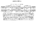
複数のSONET装置(以下、ノードと称する。)によって構築されるネットワークにおいて、図19に示すように、各ノードN間は、ファイバ(光ファイバ)Fによって接続されている。ネットワーク内の各ノードNに着目すると、ノードは複数のインタフェーススロットを有し、ファイバ接続によって隣接するノードが1つ以上存在する。 In a network constructed by a plurality of SONET devices (hereinafter referred to as nodes), each node N is connected by a fiber (optical fiber) F as shown in FIG. Focusing on each node N in the network, the node has a plurality of interface slots, and there are one or more adjacent nodes by fiber connection.
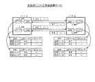
ネットワークを構築した時には、各ノードNのインタフェース間をつなぐファイバ接続が正しく行われているか否かを確認する。このため、ノード間を結ぶファイバ単位(ノードのインタフェース単位)に、ユーザが、送信側ではユニークなJ0バイトを設定して送信し、また受信側では期待するJ0バイトの値を手動で設定し、対向するノード(インタフェース)間で、設定されたJ0バイト受信期待値が受信できていることを確認することで、ファイバ接続の正常性を検証する。 When the network is constructed, it is confirmed whether or not the fiber connection between the interfaces of each node N is correctly performed. For this reason, the user sets and sends a unique J0 byte on the sending side to the fiber unit (node interface unit) connecting the nodes, and manually sets the expected J0 byte value on the receiving side. The normality of the fiber connection is verified by confirming that the set expected J0 byte reception value can be received between the opposing nodes (interfaces).
これを図20及び図21を参照して具体的に説明する。 This will be specifically described with reference to FIG. 20 and FIG.
まず、ノードN#1とN#2との間を光ファイバで接続した場合、その接続が正常であるか(誤接続していないか)を確認するためにセクションオーバヘッドのJ0バイトによるSection Trace機能を利用する。
First, when connecting
図20の例では、送信側ノードN#1では、J0バイトに“AAA”を設定してインタフェースIF#3から送信し、受信側ノードN#2のインタフェースIF#10では正しい送信元から受信される期待値“AAA”をユーザが予め手動設定しておく。そして、受信側ノードN#2のインタフェースIF#10で実際に受信したJ0バイトが期待値と一致するので、インタフェースIF#3-IF#10間の接続は正常であると判定される。ノードN#2からノードN#1への逆方向においても別の期待値“BBB”を用いて接続は正常であると判定される。
In the example of FIG. 20, the transmitting side
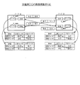
一方、図21の例では、ノードN#1のインタフェースIF#3の受信期待値が“BBB”であるにも関わらず、実際にノードN#2から受信したJ0バイトは、ノードN#2のインタフェースIF#20から送信された値“YYY”になっているため、両者は一致せず、インタフェースIF#3-IF#10間はファイバが誤接続されていると判定する。同様にして、インタフェースIF#4-IF#20間も誤接続されていると判定する。
On the other hand, in the example of FIG. 21, the J0 byte actually received from the
なお、GMPLS(Generalized Multi-Protocol Label Switching)プロトコル群の1つであるLMP(Link Management Protocol)のLink Connectivity Verificationを利用することで、ノード間の接続状態(どのノードとどのノードが接続されているか)を自動収集する方法が既にある(例えば非特許文献1参照。)。
By using Link Connectivity Verification of LMP (Link Management Protocol), which is one of the GMPLS (Generalized Multi-Protocol Label Switching) protocol group, the connection status between nodes (which node is connected to which node) ) Has already been collected automatically (see Non-Patent
また、伝送速度が64kbpsのPCM信号を24回線収容可能な1次群信号の2本と、伝送速度が32kbpsのADPCM信号を48回線収容可能な1次群信号の1本との相互符号変換を行うADPCMトランスコーダで、上記各信号の回線対応を示す回線対応情報を対向装置間で一致させる回線対応情報一致方式において、上記各信号の回線対応を示す回線対応表を上記ADPCMトランスコーダ内部にあらかじめ用意し、上記ADPCM信号を48回線収容可能な1次群信号の中のシグナリング情報を伝送する回線内に、上記回線対応表のアドレス番号を挿入し、上記対向装置間でこのアドレス番号を送受して回線対応情報を一致させることを特徴とするADPCMトランスコーダの回線対応情報一致方式がある(例えば特許文献1参照。)。
図20及び図21に示す例の場合、送信側からのJ0バイト送信値と、受信側で設定されたJ0バイト受信期待値を全てのスロット又はポート(インタフェース)においてユーザが正しく設定しないと接続の正常性を確認することができない。 In the example shown in FIG. 20 and FIG. 21, if the user does not correctly set the J0 byte transmission value from the transmission side and the J0 byte reception expectation value set on the reception side in all slots or ports (interfaces), Normality cannot be confirmed.
また、接続の正常性を確認できたとしても、各ノードがどのインタフェースと正常に接続されているかを収集することはできなかった。 Even if the normality of the connection could be confirmed, it was not possible to collect which interface each node was normally connected to.
さらに、J0バイト送信値あるいはJ0バイト受信期待値を誤って設定した場合、実際のファイバ接続は正しくても誤接続と認識されてしまったり、逆に、誤接続が発生していても接続が正常と認識されるという問題があった。 In addition, if the J0 byte transmission value or J0 byte reception expectation value is set incorrectly, the actual fiber connection may be recognized as an incorrect connection, or conversely, even if an incorrect connection has occurred, the connection is normal. There was a problem of being recognized.
また、非特許文献1の場合には、Verificationを完了するまでにIPレイヤを使用し多数のメッセージをやりとりするため、全てのスロット又はポートの接続状態の収集が完了するまでに時間を要するという問題がある。当然、ノード間のいずれか一方でもGMPLSをサポートしていない装置であれば、本機能を利用することはできない。
In addition, in the case of Non-Patent
従って、本発明は、期待値を設定しなくても迅速にファイバの誤接続を検出できる方法及び装置を実現することを目的とする。 Therefore, an object of the present invention is to realize a method and an apparatus that can quickly detect a fiber misconnection without setting an expected value.
上記の目的を達成するため、本発明に係るファイバ誤接続検出方法(又は装置)は、ヘッダの所定第1フィールドに、自ノードの信号を入出力するインタフェースの識別子を設定して受信側ノードへ送信すると共に該インタフェース識別子を保存する第1ステップ(又は手段)と、該受信側ノードにおいて、受信した該第1フィールドに設定された該インタフェース識別子を該ヘッダの所定第2フィールドに設定するとともに該受信側ノードのインタフェース識別子を設定した該第1フィールドと共に送信して来たとき、該受信した該第1及び第2フィールドにそれぞれ設定された該インタフェース識別子の内の該第2フィールドの該インタフェース識別子が、該第1ステップ(又は手段)で保存した該第1フィールドの該インタフェース識別子と一致しているときに正常と判定する第2ステップ(又は手段)と、を備えたことを特徴としている。 To achieve the above object, a fiber erroneous connection detection method according to the present invention (or device), to a predetermined first field of the header, the receiving node sets the identifier of the interface for input and output signals of the node a first step (or means) that stores the interface identifier and transmits to, in said receiving node, and sets the interface identifier set in the first field received in a predetermined second field of the header when came sent with the first field to set the interface identifier of the receiving node, the interface of the second field of the said interface identifier set respectively to the first and second field thus received An identifier matches the interface identifier of the first field stored in the first step (or means) And a second step (or means) for determining that the operation is normal.
すなわち、本発明では、例えば図1(1)に示すようにJ0バイト(又はJ0バイト以外のセクションオーバヘッドの空き領域)を用い、このJ0バイトに、対向するノードの、信号を入出力するインタフェース(スロット又はポート)の識別子(ID)(好ましくはノード識別子も一緒に)を埋め込むためのフィールドを、ヘッダの所定第1フィールドとして設け、各ノードにおいて、自ノードのインタフェース識別子をJ0バイトの第1(上位)フィールドに書き込む。これにより、各ノードから送信されるJ0バイト中に各ノードのインタフェース識別子が含まれるようになる。 That is, in the present invention, for example, as shown in FIG. 1 (1), a J0 byte (or a section overhead free space other than the J0 byte) is used, and an interface for inputting / outputting a signal of an opposite node to this J0 byte ( A field for embedding the identifier (ID) (preferably together with the node identifier ) of the slot or port) is provided as a predetermined first field of the header . At each node, the interface identifier of its own node is set to the first ( Write to the upper field. As a result, the interface identifier of each node is included in the J0 byte transmitted from each node.
受信側ノードにおいては、受信したJ0バイト中の第1フィールドに格納されている値を、送信用のJ0バイトの第2(下位)フィールドに格納(コピー)する。このような第1及び第2フィールドを含むJ0バイトを送信することにより、一方のノードでは、他方のノードのインタフェース識別子を取得できる。 In the receiving side node, the value stored in the first field in the received J0 byte is stored (copied) in the second (lower) field of the J0 byte for transmission. By transmitting such a J0 byte including the first and second fields, one node can acquire the interface identifier of the other node.
上記の動作を続けることで、受信側ノードでは、対向ノードと自ノードのインタフェース識別子が保持されることになる。各ノードにおいては、送信用のJ0バイトの第1フィールドと受信J0バイトの第2フィールドとを比較する。この結果、両者が一致する場合、ファイバの接続は同一インタフェース間で正常に接続されているということになる。 By continuing the above operation, the receiving side node holds the interface identifiers of the opposite node and the own node. At each node, the first field of the J0 byte for transmission is compared with the second field of the received J0 byte. As a result, if the two match, the fiber connection is normally connected between the same interfaces.
上記の比較の結果、不一致が起きた場合、ファイバの接続は異なるインタフェースと接続されていることを示すため、自インタフェース及び誤接続先インタフェースが分かるような形でユーザに対してアラーム通知を行う。このアラーム通知により、ファイバ誤接続が発生していることを、ユーザが確認することができる。 If a mismatch occurs as a result of the above comparison, an alarm notification is given to the user in such a way that the own interface and the erroneous connection destination interface are known to indicate that the fiber connection is connected to a different interface. This alarm notification allows the user to confirm that a fiber misconnection has occurred.
また、上記第1及び第2フィールドに加えて第3フィールドに期待値を設定して送信する第4ステップ(又は手段)と、該期待値を受信したとき、この期待値が予め設定されている受信期待値とが一致しているか否かを判定する第5ステップ(又は手段)と、をさらに備えてもよい。 Also, a fourth step (or means) for setting and transmitting an expected value in the third field in addition to the first and second fields, and when the expected value is received, this expected value is preset. A fifth step (or means) for determining whether or not the expected reception value matches may be further included.
従って、上記のとおり、第3ステップ(又は手段)で正常と判定しても、該5ステップ(又は手段)で不一致判定したときには、受信期待値の設定が誤っていたと判定することができる。 Therefore, as described above, even if it is determined to be normal in the third step (or means), it can be determined that the setting of the expected reception value is incorrect when the mismatch is determined in the five steps (or means).
以上のように本発明により、対向するノードのインタフェース同士間の誤接続を期待値やGMPLのサポート無しで迅速に検出できる。また、各ノードにおいて、対向するノードとのファイバ接続情報を収集することができる。 As described above, according to the present invention, it is possible to quickly detect an erroneous connection between interfaces of opposing nodes without an expected value or GMPL support. Further, in each node, it is possible to collect fiber connection information with the opposite node.
実施例[1]:図2〜図13
図2は、実施例[1]による各ノード内の各インタフェース(スロット又はポート)の構成を示したものである。各インタフェースIFは、光信号をファイバF1から入力する光入力部1と、光信号をファイバF2に出力する光出力部2と、J0バイト管理テーブル3と、光入力部1から入力したJ0バイトの受信値からJ0バイト管理テーブル3に格納されている情報を用いてJ0バイトの送信値を作成して光出力部2に送るJ0バイト送信値処理部4と、J0バイト管理テーブル3の情報に基づいて適宜アラームを発生する誤接続検出処理部5とで構成されている。
Example [1]: FIGS. 2 to 13
FIG. 2 shows a configuration of each interface (slot or port) in each node according to the embodiment [1]. Each interface IF includes an
上記のJ0バイト管理テーブル3の実施例が図3に示されており、J0バイト送受信値処理部4の動作フローが図4に示されており、そして誤接続検出処理部5の動作フローが図5に示されている。これら図3〜図5の説明は、以下に述べる、図2に示したインタフェースにおける正常接続動作(1)〜(4)及び誤接続動作(1)〜(4)の中で順次行う。
An example of the above-described J0 byte management table 3 is shown in FIG. 3, the operation flow of the J0 byte transmission / reception
◎正常接続動作:図6〜図9
・動作(1):図6
まず、対向するノードA及びBにおいて、ノードAのインタフェースIF#5及びIF#6が、それぞれJ0バイト管理テーブル3_A#5及び3_A#6を有し、ノードBのインタフェースIF#7及びIF#8が、それぞれJ0バイト管理テーブル3_B#7及び3_B#8を有する。これらのJ0バイト管理テーブル3は、図3(1)及び(2)にそれぞれ示した送信及び受信フィールド(領域)を有し、符号「3」で総称することがある。
◎ Normal connection operation: Fig. 6 to Fig. 9
・ Operation (1): Fig. 6
First, in the opposite nodes A and B, the
ノードAのインタフェースIF#5から送信されるJ0バイトについて、ノードAは、図3(1)に示す送信フィールド中の上位フィールドに、図6のJ0バイト管理テーブル3_A#5に示すように自ノードID:AのインタフェースIFID:5(図では識別子として“A-5”と表記する。)という情報を格納したJ0バイトをノードBに対して送信する。このとき、J0バイト送受信値処理部4では、図4に示すステップS1〜S3を経由してステップS4を実行することになる。
For the J0 byte transmitted from the
同様にして、ノードAのインタフェースIF#6からノードBに対して、上位フィールドに識別子“A-6”が設定されたJ0バイトが送信され、また、ノードBのインタフェースIF#7及びIF#8からノードAに対して、それぞれ、上位フィールドに識別子“B-7”及び“B-8”が設定されたJ0バイトが送信される。
Similarly, the J0 byte having the identifier “A-6” set in the upper field is transmitted from the
・動作(2):図7
ノードAからのJOバイトを受信したノードBでは、例えば上位フィールドに識別子“A-5”が設定されたJ0バイトの場合、図7のインタフェースIF#7のJ0バイト管理テーブル3_B#7に示すように、その受信フィールド(図3(2)参照。)の上位フィールドに識別子“A-5”を格納する(ステップS5)。
・ Operation (2): Fig. 7
In the node B that receives the JO byte from the node A, for example, in the case of the J0 byte in which the identifier “A-5” is set in the upper field, as shown in the J0 byte management table 3_B # 7 of the
同様にして、ノードAから上位フィールドに識別子“A-6”が設定されたJ0バイトを受信したノードBのインタフェースIF#6は、そのテーブル3_B#8の受信フィールドの上位フィールドにおいて識別子“A-6”が設定される。同様にして、ノードAのJ0バイト管理テーブル3_A#5及び3_A#6においても、図7に示す通り、インタフェースIF#5及びIF#6で受信したJ0バイトにより受信フィールドの上位フィールドにおいてそれぞれ識別子“B-7”及び“B-8”が格納される。
Similarly, the
・動作(3):図8
ノードBにおいては、J0バイト管理テーブル3_B#7の受信フィールドの上位フィールドに格納された識別子“A-5”をコピーして送信フィールドの下位フィールドに格納する(ステップS6)。
・ Operation (3): Fig. 8
In the node B, the identifier “A-5” stored in the upper field of the reception field of the J0 byte management
同様にして、ノードBのテーブル3_B#8においても、その受信フィールドの上位フィールドに格納された識別子“A-6”をコピーして送信フィールドの下位フィールドに格納する。さらに同様にして、ノードAのテーブル3_A#5及び3_A#6においても、それぞれ、受信フィールドにおける上位フィールドに格納された識別子“B-7”及び“B-8”をコピーして送信フィールドの下位フィールドに格納する。
Similarly, in the
このようにして、ノードAのテーブル3_A#5及び3_A#6並びにノードBのテーブル3_B#7及び3_B#8において、送信フィールドには、上位フィールド及び下位フィールドがそれぞれ自ノードの識別子(ノード識別子+インタフェース識別子)及び対向ノードの識別子(同)を保持することになる。
In this way, in the
そして、このような状態において、J0バイト送受信値処理部4は、各J0バイト管理テーブル3の送信フィールドに設定されている上位フィールド及び下位フィールドの識別子を光出力部2を介してファイバF2に送出する(ステップS4)。
In such a state, the J0 byte transmission / reception
・動作(4):図9
上記の動作(3)におけるステップS4により、ノードBのインタフェースIF#7は、ノードAのインタフェースIF#5から、上位フィールドが“A-5”で下位フィールドが“B-7”に設定されたJ0バイトを受信するので、J0バイト送受信値処理部4は、上記の動作(2)と同様にして、テーブル3_B#7における受信フィールドに、図9に示す如く、上位フィールドに“A-5”を上書きし、下位フィールドに“B-7”を格納する。
・ Operation (4): Fig. 9
In step S4 in the above operation (3), the interface IF # 7 of the node B is set to “A-5” in the upper field and “B-7” in the lower field from the interface IF # 5 of the node A. Since the J0 byte is received, the J0 byte transmission / reception
同様にして、ノードBのJ0バイト管理テーブル3_B#8の受信フィールドには、ノードAのインタフェースIF#6から送られて来たJOバイトにおける上位フィールドの識別子“A-6”及び下位フィールドの識別子“B-8”が、それぞれ、上位フィールド及び下位フィールドに格納されることになる。
Similarly, in the reception field of the node B's J0 byte management
さらに同様にして、ノードAのJ0バイト管理テーブル3_A#5においても、ノードBのインタフェースIF#7から送られて来たJ0バイトにおける上位フィールドの識別子“B-7”及び下位フィールドの識別子“A-5”が、それぞれ図9に示すように、受信フィールドにおける上位フィールド及び下位フィールドに格納される。さらに同様にして、ノードAのテーブル3_A#6においても、ノードBのインタフェースIF#8からのJ0バイトにおける上位フィールドの識別子“B-8”及び下位フィールドの識別子“A-6”が、受信フィールドにおける上位フィールド及び下位フィールドにそれぞれ格納されることとなる。
Similarly, in the node A's J0 byte management
このようにして、各テーブルにおいて送信フィールド及び受信フィールドに識別子が格納されると、誤接続検出処理部5においては、これらのJ0バイト管理テーブル3上の受信J0バイト値を取得した後(ステップS11)、受信J0バイトの下位フィールド初期値でないことを確認して(ステップS12)、J0バイト管理テーブル上の送信フィールドの識別子を取得する(ステップS14)。この後、各テーブルにおいて、点線で示すように、送信フィールドにおける上位フィールドと、受信フィールドにおける下位フィールドの値が一致するか否かを判定する(ステップS15)。
Thus, when identifiers are stored in the transmission field and the reception field in each table, the erroneous connection
この判定の結果、図9の例では両者が一致するので、アラームは発生させない(ステップS13)。なお、アラームを発生させている状態の場合にはアラームを解除することになる。 As a result of this determination, in the example of FIG. 9, since both match, no alarm is generated (step S13). In the case where an alarm is generated, the alarm is canceled.
このように、テーブル3における送信フィールドの上位フィールドと受信フィールドの下位フィールドが一致することになり、誤接続が発生していないと判定することができる。 Thus, the upper field of the transmission field in Table 3 matches the lower field of the reception field, and it can be determined that no erroneous connection has occurred.
また、接続関係としては、J0バイト管理テーブル3により、ノードAのインタフェースIF#5とノードBのインタフェースIF#7、及びノードAのインタフェースIF#6とノードBのインタフェースIF#8とが正常接続されていることがノードA及びBの双方において確認することができる。 As for the connection relationship, the J0 byte management table 3 normally connects the interface IF # 5 of node A and the interface IF # 7 of node B, and the interface IF # 6 of node A and interface IF # 8 of node B. This can be confirmed in both nodes A and B.
◎誤接続動作:図10〜図13
まず、この例における誤接続は、ノードAにおけるインタフェースIF#5とIF#6のファイバを逆に接続してしまったことに起因するものである。
◎ Incorrect operation: Fig. 10 to Fig. 13
First, the erroneous connection in this example is caused by connecting the fibers of the interfaces IF # 5 and IF # 6 in the node A in reverse.
・動作(1):図10
この動作(1)は、図6に示した正常接続時の動作(1)と同様である。
・ Operation (1): Fig. 10
This operation (1) is the same as the operation (1) at the time of normal connection shown in FIG.
・動作(2):図11
上記のとおり、ノードAにおけるインタフェースIF#5とIF#6はファイバが入れ違って接続されてしまったため、この動作(2)においては、ノードBのインタフェースIF#7からのJ0バイトはノードAのインタフェースIF#6に与えられることとなる。従って、ノードAのJ0バイト管理テーブル3_A#6は、図11に示すように、受信フィールドにおける上位フィールドに識別子“B-7”が格納される。同様に、ノードAのインタフェースIF#5がノードBのインタフェースIF#8からJ0バイトを入力することにより、ノードAのJ0バイト管理テーブル3_A#5は、図示の如くその受信フィールドの上位フィールドに識別子“B-8”が格納される。なお、テーブル3_B#7及び3_B#8においては、それぞれ受信フィールドにおける上位フィールドは正常接続時と同じ識別子が格納される。
・ Operation (2): Fig. 11
As described above, the interfaces IF # 5 and IF # 6 at node A were connected because the fibers were misplaced. In this operation (2), the J0 byte from interface B # of node B is the interface of node A. Will be given to IF # 6. Accordingly, in the J0 byte management
・動作(3):図12
この動作(3)では、図8に示した正常接続時の動作(3)と同様に各J0バイト管理テーブル3における受信フィールドの上位フィールドに格納されている識別子をコピーしてそれぞれ送信フィールドにおける下位フィールドに格納する。
・ Operation (3): Fig. 12
In this operation (3), as in the normal connection operation (3) shown in FIG. 8, the identifier stored in the upper field of the reception field in each J0 byte management table 3 is copied, and the lower field in each transmission field is copied. Store in the field.
そして、各テーブル3における送信フィールドの識別子を設定したJ0バイトを対向ノードに送信する。 Then, the J0 byte in which the identifier of the transmission field in each table 3 is set is transmitted to the opposite node.
・動作(4):図13
図12に示した動作(3)によりJ0バイトの送信が行われると、図13に示すように、各テーブル3においては、対向するノードから送られて来たJ0バイトに設定された上位フィールド及び下位フィールドが受信フィールドの上位フィールド及び下位フィールドにそれぞれ格納されることになる。
・ Operation (4): Fig. 13
When the J0 byte is transmitted by the operation (3) shown in FIG. 12, as shown in FIG. 13, in each table 3, the upper field set in the J0 byte sent from the opposite node and The lower field is stored in the upper field and the lower field of the reception field, respectively.
この結果、ノードAのJ0バイト管理テーブル3_A#5においては、ノードBのインタフェースIF#8から送られて来たJ0バイトにおける上位フィールドの識別子“B-8”及び下位フィールドの識別子“A-6”がそれぞれ受信フィールドの上位フィールド及び下位フィールドに格納される。同様にして、ノードAのJ0バイト管理テーブル3_A#6の受信フィールドにおいても、ノードBのインタフェースIF#7から送られて来たJ0バイトに設定されている上位フィールドの識別子“B-7”及び下位フィールドの識別子“A-5”が設定されることになる。
As a result, in the J0 byte management
このように設定されると、誤接続検出処理部5においては、ステップS11,S12,及びS14を介してステップS15において送信フィールドにおける上位フィールドの識別子と、受信フィールドにおける下位フィールドの識別子とを比較した結果、点線で図示したように、いずれのテーブル3においても不一致となるので、誤接続アラーム通知を行う(ステップS16)。
When set in this manner, the erroneous connection
このようにして、送信フィールドの上位フィールドと受信フィールドの下位フィールドが異なるため、誤接続を発生していることを検出し、自ポート及び誤接続先ポートが分かるような形でユーザに対してアラーム通知を行うことが可能となる。 In this way, since the upper field of the transmission field is different from the lower field of the reception field, it is detected that an erroneous connection has occurred, and an alarm is given to the user in such a way that the own port and the erroneous connection destination port are known. Notification can be performed.
実施例[2]:図14〜図18
図14は、本発明の実施例[2]による各ノード内の各インタフェースの構成例を示したもので、この構成例と、図2に示した実施例[1]による各インタフェースの動作例との違いは、J0バイト受信値/受信期待値不一致検出処理部6を設けている点である。
Example [2]: FIGS. 14 to 18
FIG. 14 shows a configuration example of each interface in each node according to the embodiment [2] of the present invention. This configuration example and an operation example of each interface according to the embodiment [1] shown in FIG. The difference is that a J0 byte received value / received expected value mismatch
この実施例[2]によるインタフェースIFにおいて用いられるJ0バイト管理テーブルの構成例が図15に示されている。この実施例においては、同図(1)及び(2)にそれぞれ示す48バイトの送信フィールド及び受信フィールドにおける“TraceString”を実際に用いる点と、同図(3)に示すように、受信期待値として48バイトのTrace Stringが予め受信側ノードで設定されている点が、図3に示した実施例[1]によるテーブル例と異なっている。 A configuration example of the J0 byte management table used in the interface IF according to the embodiment [2] is shown in FIG. In this embodiment, the actual use of the “TraceString” in the 48-byte transmission field and the reception field shown in FIGS. (1) and (2), respectively, and as shown in FIG. Is different from the table example according to the embodiment [1] shown in FIG. 3 in that a 48-byte Trace String is preset in the receiving node.
また、不一致検出処理部6の動作フローが図16に示されているが、この不一致検出処理部6の動作については、以下に説明する正常接続動作例において言及する。
Further, FIG. 16 shows an operation flow of the mismatch
・動作(1):図17
この動作においては、インタフェース間の接続が正常に行われているため、図6に示した正常接続動作(1)と同様のJ0バイトがノードA-B間で送受信されるが、これに加えてノードAのインタフェースIF#5から送信されるJ0バイトにはTraceStringに“AAA”が格納される。同様にして、ノードBのインタフェースIF#7からのJ0バイトのTrace Stringには“BBB”が格納されて送信され、ノードAのインタフェースIF#6からのJ0バイトのTrace Stringには“CCC”が格納されて送信され、そして、ノードBのインタフェースIF#8からのJ0バイトのTrace Stringには“DDD”が格納されて送信される。
・ Operation (1): Fig. 17
In this operation, since the connection between the interfaces is normally performed, the J0 byte similar to the normal connection operation (1) shown in FIG. 6 is transmitted / received between the nodes AB, but in addition to this, the node A “AAA” is stored in TraceString in the J0 byte transmitted from the interface IF # 5. Similarly, “BBB” is stored and transmitted in the Trace String of the J0 byte from the interface IF # 7 of the node B, and “CCC” is stored in the Trace String of the J0 byte from the interface IF # 6 of the node A. “DDD” is stored and transmitted in the Trace String of the J0 byte from the interface IF # 8 of the Node B.
・動作(2):図18
この動作においては、正常接続が行われているので、図9に示す正常接続動作(4)と同様のテーブル内容が得られる。従って、誤接続は発生していないことが分かる。
・ Operation (2): Fig. 18
In this operation, since normal connection is performed, the same table contents as in the normal connection operation (4) shown in FIG. 9 are obtained. Therefore, it can be seen that no erroneous connection has occurred.
ただし、ノードBにおいて、インタフェースIF#3に対してユーザが設定したJ0バイトの受信期待値“ZZZ”と、実際にインタフェースIF#3から受信したJ0バイトのTrace Stringに設定されている値“CCC”とを比較すると(図16のステップS25)、両者は異なるため、この場合は、既存の接続検証の結果がエラーとなる(ステップS26)。 However, at node B, the expected J0 byte reception value “ZZZ” set by the user for interface IF # 3 and the value “CCC” set in the J0 byte Trace String actually received from interface IF # 3 ”(Step S25 in FIG. 16), the two are different. In this case, the result of the existing connection verification is an error (step S26).
この場合、上記のとおり誤接続は検出されておらず、ノードA-B間のファイバ接続は正常と判定されているので、ファイバの接続原因は、ユーザがノードBのインタフェースIF#8に対して設定を行ったJ0バイトの受信期待値の設定ミスであると判定することが可能となる。従って、このような受信期待値と受信値との不一致の場合には、アラーム通知を行う(ステップS26)。 In this case, no incorrect connection has been detected as described above, and the fiber connection between the nodes AB has been determined to be normal, so the cause of the fiber connection is set by the user on the interface IF # 8 of the node B. It can be determined that the received expected value of the J0 byte has been set incorrectly. Therefore, when there is a mismatch between the expected reception value and the received value, an alarm notification is performed (step S26).
なお、本発明は、上記実施例によって限定されるものではなく、特許請求の範囲の記載に基づき、当業者によって種々の変更が可能なことは明らかである。
It should be noted that the present invention is not limited to the above-described embodiments, and it is apparent that various modifications can be made by those skilled in the art based on the description of the scope of claims.
(付記1)
ヘッダの所定第1フィールドに自ノードのノード識別子、及び信号を入出力するインタフェースの識別子を設定して受信側ノードへ送信する第1ステップと、
該受信側ノードから該第1フィールドに設定された両識別子を受信したとき、両識別子を該ヘッダの所定第2フィールドに設定して該第1フィールドと共に送信し且つ保存する第2ステップと、
該第1及び第2フィールドに設定された識別子を受信したとき、これらの内の該第2フィールドの識別子が、該第2ステップで保存した該第1フィールドの識別子と一致しているときに正常と判定する第3ステップと、
を備えたことを特徴とするファイバ誤接続検出方法。
(付記2)付記1において、
該第1及び第2フィールドとして、J0バイト又はJ0バイト以外のセクションオーバヘッドの空き領域を用いることを特徴とするファイバ誤接続検出方法。
(付記3)付記1において、
該第3ステップが、正常と判定しなかった時、インタフェース及び誤接続先が分かる形でアラームを発生するステップを含むことを特徴とするファイバ誤接続検出方法。
(付記4)付記1において、
上記第1及び第2フィールドに加えて第3フィールドに期待値を設定して送信する第4ステップと、
該期待値を受信したとき、この期待値が予め設定されている受信期待値とが一致しているか否かを判定する第5ステップと、
をさらに備えたことを特徴とするファイバ誤接続検出方法。
(付記5)付記4において、
該第3ステップで正常と判定しても、該5ステップで不一致判定したときには、受信期待値の設定が誤っていたと判定する第6ステップをさらに備えたことを特徴とするファイバ誤接続検出方法。
(付記6)付記5において、
該第1〜第3フィールドが、J0バイト又はJ0バイト以外のセクションオーバヘッドの空き領域を用いることを特徴とするファイバ誤接続検出方法。
(付記7)付記1から6のいずれか1つにおいて、
該インタフェースが、スロット又はポートであることを特徴とするファイバ誤接続検出方法。
(付記8)
ヘッダの所定第1フィールドに自ノードのノード識別子、及び信号を入出力するインタフェースの識別子を設定して受信側ノードへ送信する第1手段と、
該受信側ノードから該第1フィールドに設定された両識別子を受信したとき、両識別子を該ヘッダの所定第2フィールドに設定して該第1フィールドと共に送信し且つ保存する第2手段と、
該第1及び第2フィールドに設定された識別子を受信したとき、これらの内の該第2フィールドの識別子が、該第2手段で保存した該第1フィールドの識別子と一致しているときに正常と判定する第3手段と、
を備えたことを特徴とするファイバ誤接続検出装置。
(付記9)付記8において、
該第1及び第2フィールドとして、J0バイト又はJ0バイト以外のセクションオーバヘッドの空き領域を用いることを特徴とするファイバ誤接続検出装置。
(付記10)付記8において、
該第3ステップが、正常と判定しなかった時、インタフェース及び誤接続先が分かる形でアラームを発生する手段を含むことを特徴とするファイバ誤接続検出装置。
(付記11)付記8において、
上記第1及び第2フィールドに加えて第3フィールドに期待値を設定して送信する第4手段と、
該期待値を受信したとき、この期待値が予め設定されている受信期待値とが一致しているか否かを判定する第5手段と、
をさらに備えたことを特徴とするファイバ誤接続検出装置。
(付記12)付記11において、
該第3手段で正常と判定しても、該5手段で不一致判定したときには、受信期待値の設定が誤っていたと判定する第6手段をさらに備えたことを特徴とするファイバ誤接続検出装置。
(付記13)付記12において、
該第1〜第3フィールドが、J0バイト又はJ0バイト以外のセクションオーバヘッドの空き領域を用いることを特徴とするファイバ誤接続検出装置。
(付記14)付記8から13のいずれか1つにおいて、
該インタフェースが、スロット又はポートであることを特徴とするファイバ誤接続検出装置。
(Appendix 1)
A first step of setting a node identifier of the own node and an identifier of an interface for inputting / outputting a signal in a predetermined first field of the header and transmitting the same to the receiving side node;
A second step of receiving both identifiers set in the first field from the receiving node, setting both identifiers in a predetermined second field of the header, transmitting and storing together with the first field;
When the identifiers set in the first and second fields are received, normal when the identifiers of the second field of these match the identifiers of the first field stored in the second step A third step of determining
A fiber misconnection detection method comprising:
(Appendix 2) In
An erroneous fiber misconnection detection method using a J0 byte or an empty area of a section overhead other than the J0 byte as the first and second fields.
(Appendix 3) In
An erroneous fiber connection detection method, wherein the third step includes a step of generating an alarm in such a manner that an interface and an erroneous connection destination are known when it is not determined to be normal.
(Appendix 4) In
A fourth step of setting and transmitting an expected value in the third field in addition to the first and second fields, and
When receiving the expected value, a fifth step of determining whether or not the expected value matches a preset received expected value;
A fiber misconnection detection method, further comprising:
(Appendix 5) In
A fiber misconnection detection method, further comprising: a sixth step of determining that the setting of the expected reception value is incorrect when it is determined to be normal in the third step even if it is determined to be inconsistent in the fifth step.
(Appendix 6) In
The fiber misconnection detection method, wherein the first to third fields use a J0 byte or a free area of a section overhead other than the J0 byte.
(Appendix 7) In any one of
A fiber misconnection detection method, wherein the interface is a slot or a port.
(Appendix 8)
A first means for setting a node identifier of the own node and an identifier of an interface for inputting and outputting a signal in a predetermined first field of the header and transmitting to the receiving side node;
A second means for receiving both identifiers set in the first field from the receiving node, setting both identifiers in a predetermined second field of the header, and transmitting and storing together with the first field;
When the identifiers set in the first and second fields are received, the identifier in the second field is normal when the identifier in the first field stored in the second means is the same. A third means for determining,
A fiber misconnection detection device comprising:
(Appendix 9) In
An erroneous fiber connection detection apparatus using a J0 byte or an empty area of a section overhead other than the J0 byte as the first and second fields.
(Appendix 10) In
An erroneous fiber connection detection device comprising means for generating an alarm in such a manner that the interface and the erroneous connection destination are known when the third step is not determined to be normal.
(Appendix 11) In
A fourth means for setting and transmitting an expected value in the third field in addition to the first and second fields;
A fifth means for determining whether or not the expected value matches a preset received expected value when the expected value is received;
A fiber misconnection detection device, further comprising:
(Appendix 12) In Appendix 11,
A fiber misconnection detection apparatus, further comprising: sixth means for determining that the setting of the expected reception value is incorrect when the third means determines normality even when the third means determines normality.
(Appendix 13) In Appendix 12,
The fiber misconnection detection apparatus, wherein the first to third fields use a J0 byte or an empty area of a section overhead other than the J0 byte.
(Supplementary note 14) In any one of
The fiber misconnection detection device, wherein the interface is a slot or a port.
1 光入力部
2 光出力部
3, 3_A#5, 3_A#6, 3_A#7, 3_A#8 J0バイト管理テーブル
4 J0バイト送受信値処理部
5 誤接続検出処理部
6 J0バイト受信値/受信期待値不一致検出処理部
A, B ノード
IF インタフェース
図中、同一符号は同一又は相当部分を示す。
1 Optical input section
2 Optical output section
3,
4 J0 byte send / receive value processor
5 Incorrect connection detection processor
6 J0 byte received value / received expected value mismatch detection processor
A, B node
IF interface In the figure, the same reference numerals indicate the same or corresponding parts.
Claims (10)
該受信側ノードにおいて、受信した該第1フィールドに設定された該インタフェース識別子を該ヘッダの所定第2フィールドに設定するとともに該受信側ノードのインタフェース識別子を設定した該第1フィールドと共に送信して来たとき、該受信した該第1及び第2フィールドにそれぞれ設定された該インタフェース識別子の内の該第2フィールドの該インタフェース識別子が、該第1ステップで保存した該第1フィールドの該インタフェース識別子と一致しているときに正常と判定する第2ステップと、
を備えたことを特徴とするファイバ誤接続検出方法。 A predetermined first field of the header, a first step of storing the interface identifier transmits by setting the identifier of an interface that inputs and outputs signals of the own node to the receiving node,
In said receiving node, came the interface identifier set in the first field received by sending together with the first field to set the interface identifier of the receiving node and sets a predetermined second field of the header when in, the interface identifier of the second field of the said interface identifier set respectively to the first and second field thus received are, and said interface identifier of the first field stored in the first step A second step of determining normality when they match,
A fiber misconnection detection method comprising:
該第1及び第2フィールドとして、J0バイト又はJ0バイト以外のセクションオーバヘッドの空き領域を用いることを特徴とするファイバ誤接続検出方法。 In claim 1,
An erroneous fiber misconnection detection method using a J0 byte or an empty area of a section overhead other than the J0 byte as the first and second fields.
該第1及び第2フィールドに該識別子に加えて自ノードのノード識別子も設定されることを特徴とするファイバ誤接続検出方法。 In claim 1,
In addition to the identifier, a node identifier of the own node is set in the first and second fields, and a fiber misconnection detection method is provided.
上記第1及び第2フィールドに加えて第3フィールドに期待値を設定して送信する第4ステップと、
該期待値を受信したとき、この期待値が予め設定されている受信期待値とが一致しているか否かを判定する第5ステップと、
をさらに備えたことを特徴とするファイバ誤接続検出方法。 In claim 1,
A fourth step of setting and transmitting an expected value in the third field in addition to the first and second fields, and
When receiving the expected value, a fifth step of determining whether or not the expected value matches a preset received expected value;
A fiber misconnection detection method, further comprising:
該第3ステップで正常と判定しても、該5ステップで不一致判定したときには、受信期待値の設定が誤っていたと判定する第6ステップをさらに備えたことを特徴とするファイバ誤接続検出方法。 In claim 4,
A fiber misconnection detection method, further comprising: a sixth step of determining that the setting of the expected reception value is incorrect when it is determined to be normal in the third step even if it is determined to be inconsistent in the fifth step.
該受信側ノードにおいて、受信した該第1フィールドに設定された該インタフェース識別子を該ヘッダの所定第2フィールドに設定するとともに該受信側ノードのインタフェース識別子を設定した該第1フィールドと共に送信して来たとき、該受信した該第1及び第2フィールドにそれぞれ設定された該インタフェース識別子の内の該第2フィールドの該インタフェース識別子が、該第1手段で保存した該第1フィールドの該インタフェース識別子と一致しているときに正常と判定する第2手段と、
を備えたことを特徴とするファイバ誤接続検出装置。 A predetermined first field of the header, a first means for storing the interface identifier transmits by setting the identifier of an interface that inputs and outputs signals of the own node to the receiving node,
In said receiving node, came the interface identifier set in the first field received by sending together with the first field to set the interface identifier of the receiving node and sets a predetermined second field of the header when in, the interface identifier of the second field of the said interface identifier set respectively to the first and second field thus received are, and said interface identifier of the first field stored in said first means A second means for determining normality when they match,
A fiber misconnection detection device comprising:
該第1及び第2フィールドとして、J0バイト又はJ0バイト以外のセクションオーバヘッドの空き領域を用いることを特徴とするファイバ誤接続検出装置。 In claim 6,
An erroneous fiber connection detection apparatus using a J0 byte or an empty area of a section overhead other than the J0 byte as the first and second fields.
該第1及び第2フィールドに該識別子に加えて自ノードのノード識別子も設定されることを特徴とするファイバ誤接続検出装置。 In claim 6,
In addition to the identifier, a node identifier of the own node is also set in the first and second fields .
上記第1及び第2フィールドに加えて第3フィールドに期待値を設定して送信する第4手段と、
該期待値を受信したとき、この期待値が予め設定されている受信期待値とが一致しているか否かを判定する第5手段と、
をさらに備えたことを特徴とするファイバ誤接続検出装置。 In claim 6,
A fourth means for setting and transmitting an expected value in the third field in addition to the first and second fields;
A fifth means for determining whether or not the expected value matches a preset received expected value when the expected value is received;
A fiber misconnection detection device, further comprising:
該第3手段で正常と判定しても、該5手段で不一致判定したときには、受信期待値の設定が誤っていたと判定する第6手段をさらに備えたことを特徴とするファイバ誤接続検出装置。 In claim 9,
A fiber misconnection detection apparatus, further comprising: sixth means for determining that the setting of the expected reception value is incorrect when the third means determines normality even when the third means determines normality.
Priority Applications (2)
| Application Number | Priority Date | Filing Date | Title |
|---|---|---|---|
| JP2006249479A JP5034397B2 (en) | 2006-09-14 | 2006-09-14 | Fiber misconnection detection method and apparatus |
| US11/751,083 US8135284B2 (en) | 2006-09-14 | 2007-05-21 | Fiber misconnection detecting method and device |
Applications Claiming Priority (1)
| Application Number | Priority Date | Filing Date | Title |
|---|---|---|---|
| JP2006249479A JP5034397B2 (en) | 2006-09-14 | 2006-09-14 | Fiber misconnection detection method and apparatus |
Publications (2)
| Publication Number | Publication Date |
|---|---|
| JP2008072462A JP2008072462A (en) | 2008-03-27 |
| JP5034397B2 true JP5034397B2 (en) | 2012-09-26 |
Family
ID=39188728
Family Applications (1)
| Application Number | Title | Priority Date | Filing Date |
|---|---|---|---|
| JP2006249479A Expired - Fee Related JP5034397B2 (en) | 2006-09-14 | 2006-09-14 | Fiber misconnection detection method and apparatus |
Country Status (2)
| Country | Link |
|---|---|
| US (1) | US8135284B2 (en) |
| JP (1) | JP5034397B2 (en) |
Families Citing this family (4)
| Publication number | Priority date | Publication date | Assignee | Title |
|---|---|---|---|---|
| CN101582719A (en) * | 2009-06-18 | 2009-11-18 | 中兴通讯股份有限公司 | Method and system for obtaining JO overhead byte as well as network element management facility and network element |
| JP2012244530A (en) * | 2011-05-23 | 2012-12-10 | Fujitsu Ltd | Erroneous fiber connection detection method and node device |
| JPWO2013140512A1 (en) * | 2012-03-19 | 2015-08-03 | 富士通株式会社 | Information processing apparatus, erroneous connection detection method, and erroneous connection detection program |
| CN103997371B (en) * | 2013-02-18 | 2018-02-13 | 中兴通讯股份有限公司 | Detection method, the device and system of optical signal |
Family Cites Families (14)
| Publication number | Priority date | Publication date | Assignee | Title |
|---|---|---|---|---|
| JPS62227240A (en) | 1986-03-29 | 1987-10-06 | Nec Corp | Line corresponding information coincidence system for adpcm transcoder |
| US6553000B1 (en) * | 1998-01-27 | 2003-04-22 | Alcatel Internetworking (Pe), Inc. | Method and apparatus for forwarding network traffic |
| US6680948B1 (en) * | 1999-02-02 | 2004-01-20 | Tyco Telecommunications (Us) Inc. | System and method for transmitting packets over a long-haul optical network |
| US6594268B1 (en) * | 1999-03-11 | 2003-07-15 | Lucent Technologies Inc. | Adaptive routing system and method for QOS packet networks |
| JP3425892B2 (en) * | 1999-04-21 | 2003-07-14 | 日立電子サービス株式会社 | Network tester and system and storage medium |
| US6680912B1 (en) * | 2000-03-03 | 2004-01-20 | Luminous Networks, Inc. | Selecting a routing direction in a communications network using a cost metric |
| US20020171886A1 (en) * | 2001-03-07 | 2002-11-21 | Quansheng Wu | Automatic control plane recovery for agile optical networks |
| US7068608B2 (en) * | 2001-12-21 | 2006-06-27 | Nortel Networks Limited | Automated method for connection discovery within consolidated network elements |
| US20030134591A1 (en) * | 2002-01-17 | 2003-07-17 | Roberts Mark Gary | Digital remote signaling system |
| US20040076151A1 (en) * | 2002-10-21 | 2004-04-22 | Walter Fant | Connection identifiers and restoration in optical networks |
| US7340163B2 (en) * | 2002-12-16 | 2008-03-04 | Alcatel Lucent | Signaling protocol and architecture for protection rings |
| US7417950B2 (en) * | 2003-02-03 | 2008-08-26 | Ciena Corporation | Method and apparatus for performing data flow ingress/egress admission control in a provider network |
| US7317914B2 (en) * | 2004-09-24 | 2008-01-08 | Microsoft Corporation | Collaboratively locating disconnected clients and rogue access points in a wireless network |
| CN1878036B (en) * | 2006-07-18 | 2010-06-09 | 华为技术有限公司 | A method for routing convergence at the control plane in an intelligent optical network |
-
2006
- 2006-09-14 JP JP2006249479A patent/JP5034397B2/en not_active Expired - Fee Related
-
2007
- 2007-05-21 US US11/751,083 patent/US8135284B2/en not_active Expired - Fee Related
Also Published As
| Publication number | Publication date |
|---|---|
| US20080069559A1 (en) | 2008-03-20 |
| US8135284B2 (en) | 2012-03-13 |
| JP2008072462A (en) | 2008-03-27 |
Similar Documents
| Publication | Publication Date | Title |
|---|---|---|
| US20040076151A1 (en) | Connection identifiers and restoration in optical networks | |
| CN101848114B (en) | Fault detection method and device | |
| CN101523803B (en) | Elastic scheme in communication network | |
| CN111164923B (en) | Designed for one-way transfer of data | |
| US7633952B2 (en) | Discovery of physically adjacent neighbor devices using a unidirectional in-band process coupled with an out-of-band follow-up process | |
| US6917763B1 (en) | Technique for verifying fiber connectivity in a photonic network | |
| RU2008109226A (en) | FAILURE-RESISTANT COMMUNICATION IN ROUTED NETWORKS | |
| CN103401726A (en) | Network path detecting method, device and system | |
| JPH04504347A (en) | Automatic failure recovery in packet networks | |
| US7515545B2 (en) | Signal repeater and switching device, method of detecting connecting relation between signal repeater and switching device and communication system | |
| EP1459481B1 (en) | Method for automated connection discovery in optical networks | |
| WO2015058497A1 (en) | Method, device, and system for optical fiber link identification | |
| US8135284B2 (en) | Fiber misconnection detecting method and device | |
| CN103959723B (en) | A kind of heavy route method, system and the network equipment | |
| CN102546018A (en) | Optical module rate shaping method and device utilizing same | |
| JP6879245B2 (en) | Wiring management system and wiring management method | |
| CN103905235A (en) | Interface configuration method and apparatus, network transmission device, and communication system | |
| CN101355386B (en) | Method for automatically discovering error connection of multiplex segment protective optical fiber | |
| CN100463387C (en) | Device and method for implementing protection switching protocol using IP communication mode | |
| US7843838B1 (en) | Communication network route tracing | |
| CN101599847A (en) | A Method for Preventing Misconnections in Ring Optical Networks | |
| US7509438B1 (en) | Bi-directional line switched ring support for path trace monitoring on a protection path | |
| JP2709212B2 (en) | Path route switching device | |
| CN101102163B (en) | Method for preventing the protection network of the loop multiplexing section from incorrect optical fiber connection and loop multiplexing section network | |
| JP3793405B2 (en) | Communication network failure recovery method |
Legal Events
| Date | Code | Title | Description |
|---|---|---|---|
| A621 | Written request for application examination |
Free format text: JAPANESE INTERMEDIATE CODE: A621 Effective date: 20090512 |
|
| A131 | Notification of reasons for refusal |
Free format text: JAPANESE INTERMEDIATE CODE: A131 Effective date: 20111108 |
|
| A521 | Written amendment |
Free format text: JAPANESE INTERMEDIATE CODE: A523 Effective date: 20120106 |
|
| TRDD | Decision of grant or rejection written | ||
| A01 | Written decision to grant a patent or to grant a registration (utility model) |
Free format text: JAPANESE INTERMEDIATE CODE: A01 Effective date: 20120605 |
|
| A01 | Written decision to grant a patent or to grant a registration (utility model) |
Free format text: JAPANESE INTERMEDIATE CODE: A01 |
|
| A61 | First payment of annual fees (during grant procedure) |
Free format text: JAPANESE INTERMEDIATE CODE: A61 Effective date: 20120618 |
|
| FPAY | Renewal fee payment (event date is renewal date of database) |
Free format text: PAYMENT UNTIL: 20150713 Year of fee payment: 3 |
|
| R150 | Certificate of patent or registration of utility model |
Free format text: JAPANESE INTERMEDIATE CODE: R150 |
|
| LAPS | Cancellation because of no payment of annual fees |