EP1432162A1 - Automatic frequency control device for ofdm and method therefor - Google Patents
Automatic frequency control device for ofdm and method therefor Download PDFInfo
- Publication number
- EP1432162A1 EP1432162A1 EP01972584A EP01972584A EP1432162A1 EP 1432162 A1 EP1432162 A1 EP 1432162A1 EP 01972584 A EP01972584 A EP 01972584A EP 01972584 A EP01972584 A EP 01972584A EP 1432162 A1 EP1432162 A1 EP 1432162A1
- Authority
- EP
- European Patent Office
- Prior art keywords
- automatic frequency
- frequency control
- value
- control device
- peak
- Prior art date
- Legal status (The legal status is an assumption and is not a legal conclusion. Google has not performed a legal analysis and makes no representation as to the accuracy of the status listed.)
- Withdrawn
Links
Images






Classifications
-
- H—ELECTRICITY
- H04—ELECTRIC COMMUNICATION TECHNIQUE
- H04L—TRANSMISSION OF DIGITAL INFORMATION, e.g. TELEGRAPHIC COMMUNICATION
- H04L27/00—Modulated-carrier systems
- H04L27/26—Systems using multi-frequency codes
- H04L27/2601—Multicarrier modulation systems
- H04L27/2647—Arrangements specific to the receiver only
- H04L27/2655—Synchronisation arrangements
- H04L27/2657—Carrier synchronisation
-
- H—ELECTRICITY
- H04—ELECTRIC COMMUNICATION TECHNIQUE
- H04L—TRANSMISSION OF DIGITAL INFORMATION, e.g. TELEGRAPHIC COMMUNICATION
- H04L27/00—Modulated-carrier systems
- H04L27/26—Systems using multi-frequency codes
- H04L27/2601—Multicarrier modulation systems
- H04L27/2647—Arrangements specific to the receiver only
- H04L27/2655—Synchronisation arrangements
- H04L27/2668—Details of algorithms
- H04L27/2673—Details of algorithms characterised by synchronisation parameters
- H04L27/2676—Blind, i.e. without using known symbols
- H04L27/2678—Blind, i.e. without using known symbols using cyclostationarities, e.g. cyclic prefix or postfix
-
- H—ELECTRICITY
- H04—ELECTRIC COMMUNICATION TECHNIQUE
- H04L—TRANSMISSION OF DIGITAL INFORMATION, e.g. TELEGRAPHIC COMMUNICATION
- H04L27/00—Modulated-carrier systems
- H04L27/26—Systems using multi-frequency codes
- H04L27/2601—Multicarrier modulation systems
- H04L27/2602—Signal structure
- H04L27/2605—Symbol extensions, e.g. Zero Tail, Unique Word [UW]
- H04L27/2607—Cyclic extensions
-
- H—ELECTRICITY
- H04—ELECTRIC COMMUNICATION TECHNIQUE
- H04L—TRANSMISSION OF DIGITAL INFORMATION, e.g. TELEGRAPHIC COMMUNICATION
- H04L5/00—Arrangements affording multiple use of the transmission path
- H04L5/0001—Arrangements for dividing the transmission path
- H04L5/0014—Three-dimensional division
- H04L5/0016—Time-frequency-code
Definitions
- the present invention relates to an automatic frequency control device in an OFDM (Orthogonal Frequency Divisional Multiplexing) transmission system and a method thereof.
- OFDM Orthogonal Frequency Divisional Multiplexing
- the third generation has been developed and is about to be put into practical use.
- wireless communication R&D departments have started to research and develop the fourth generation wireless communication system aiming at larger-capacity and higher-speed wireless communication.
- OFDM-CDMA is a strong candidate for the basic system of the fourth generation mobile communication system.
- an OFDM technology for transmitting a plurality of pieces of information in parallel using a plurality of sub-carriers each with a reciprocally orthogonal frequency and a CDMA technology using the orthogonality of a spread code by which user data is multiplied when a plurality of pieces of user data are multiplexed are united in order to realize larger-capacity, higher-quality and higher-speed communication.
- An object of the present invention is to provide an OFDM automatic frequency control device with an excellent frequency control function and a method thereof.
- the automatic frequency control device of the present invention is one in an OFDM (Orthogonal Frequency Divisional Multiplexing) system.
- the automatic frequency control device comprises correlation means for calculating a correlation value between the guard interval and data of an incoming signal, averaging means for averaging the correlation values across a plurality of symbols and a plurality of frames, peak position detecting means for detecting the peak position of the averaged correlation value and control means for controlling an oscillator using a prescribed step, based on the detected peak position.
- the automatic frequency control method of the present invention is OFDM (Orthogonal Frequency Divisional Multiplexing).
- the automatic frequency control method comprises calculating a correlation value between the guard interval and data of an incoming signal (correlation step), averaging the correlation values across a plurality of symbols and a plurality of frames (averaging step), detecting the peak position of the averaged correlation value (peak position detecting step) and controlling an oscillator using a prescribed step, based on the detected peak position (control execution step).
- the receiver's oscillator can rapidly, efficiently and accurately control the frequency, signals can be received with high-accuracy.
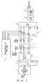
- Fig. 1 shows the basic configuration of the transmitter of an OFDM-CDMA system.
- Input user data is, for example, QPSK-modulated by a QPSK modulation mapping unit 1.
- This modulation method is one example, and modulation is not necessarily limited to QPSK.
- the modulated user data is converted from serial into parallel by a serial/parallel converter 2. For example, one symbol of the user data modulated for one time slot is output to the output a1 of the serial/parallel converter 2. Similarly, one symbol of the user data modulated in the same timing is output to the outputs a2 through an of serial/parallel converters 2.
- Such sn modulation signal symbols output from the serial/parallel converter 2 thus are copied by a copying unit 3 provided for each output. Then, each of the sn modulation signal symbols is multiplied by each chip of a spread code (in this case, a Walsh code) in a multiplier 4. In this case, the length of a Walsh code equals sn chips. Therefore, each of sn copied modulation signal symbols is multiplied by a different chip of the sn chips of a Walsh code.
- a spread code in this case, a Walsh code
- each of the modulation signal symbols that are multiplied by such a Walsh code is further multiplied by a spread code (in this case, a Gold series code) in a multiplier 5.
- a spread code in this case, a Gold series code
- a plurality of pieces of other user data transmitted from a modulation unit 7 for other users are modulated.
- Such signals processed in the same way are added in an adder 6 and are input to an IFFT (Inverse Fast Fourier Transformation) unit 8.
- Each signal input to the IFFT unit 8 is regarded to be each frequency component, inverse Fourier transformation is applied to each signal and each signal is output as one modulation wave. Specifically, if the number of inputs to the IFFT unit 8 is 1,024, the number of frequency components is 1,024. Therefore, each frequency component is carried on each of 1,024 sub-carriers. Then, the components are combined and are output from the IFFT unit 8.
- the IFFT unit 8 performs Fourier transformation using a sub-carrier with a fundamental frequency and a sub-carrier with a frequency obtained by multiplying the fundamental frequency by an integer. If the frequency of each sub-carrier can be obtained by multiplying the fundamental frequency by an integer, an integration of the product of the sub-carrier with a frequency obtained by multiplying the fundamental frequency by an integer and that with the fundamental frequency for one cycle, becomes 0 and only an integration of the product of sub-carriers with the same frequency for one cycle becomes a finite value. In other words, a sub-carrier with a specific frequency is orthogonal to a sub-carrier with a frequency obtained by multiplying the fundamental frequency by an integer. The word "orthogonal" in OFDM derives from this fact.
- a guard interval adding unit (+GI unit) 9 a guard interval, which is described later, is added to each signal wave output from the IFFT unit 8, and the signal waves each with a guard interval are transmitted. Up to this point, data are digitally processed. In a D/A converter 10, digital signals are converted into analog signals and transmitted to a transmission side.
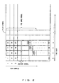
- Fig. 2 shows how each modulation signal symbol is allocated according to sub-carrier and time slots, being the vertical and horizontal axes, respectively.
- a modulation signal is packed into a frame.
- the frame is composed of at least a data section and a pilot section.
- the number of sub-carriers is 1,024.
- a Walsh code is composed of 32 chips.
- a subsequent time slot 2 accommodates symbols similarly, the multiplication methods of a Wash code and a Gold series code are different from those of time slot 1. Specifically, 1,024 chips of a code is generated by combining Walsh codes with Gold series codes. Then, for example, as shown in Fig. 2, in time slot 2, symbols are multiplied after a generated code is shifted by eight chips. In time slot 3, symbols are multiplied after the generated code is shifted by eight more chips. In time slot 4, symbols are multiplied after the generated code is shifted by another eight more chips. Thus, the multiplication timing of a spread code is shifted eight chips.
- the pilot section has a different structure from that of the data section. For example, if a time slot n accommodates one symbol of the pilot section, this pilot symbol is commonly accommodated for 1, 024 sub-carriers. Although one frame accommodates, for example, four pilot symbols, which is described later, each symbol is multiplied in the same way.
- the Walsh code multiplication method of the pilot section is different from that of the data section, which is described later.
- Fig. 3 shows the basic configuration of the receiver of an OFDM-CDMA system.
- Incoming data is first converted into digital signals by an A/D converter 15. Then, in a guard interval eliminating unit (-GI unit) 16, guard intervals are eliminated, and the resulting digital signals are input to an FFT (Fast Fourier Transformation) unit 17.
- the FFT unit 17 decomposes a signal wave for a specific time period into its frequency components by Fourier transformation. Specifically, although in a transmitter, the modulation signal symbol of user data is regarded to be frequency components and is converted into a signal wave for a specific time period by inverse-Fourier transformation, in the FFT unit 17, frequency components are extracted from a signal wave for a specific time period by Fourier transformation. That is, in this case, the modulation signal symbol of user data is extracted.
- the modulation signal symbol of the pilot section of the frequency components f1 through fn obtained by the process of the FFT unit 17 is used to calculate a channel prediction in a channel prediction unit 18.
- a channel compensation unit 19 the channel of each of the frequency components f1 through fn is compensated for.
- each of the frequency components f1 through fn is multiplied by the complex conjugate of the Gold series code used on a transmitting side.
- each of the frequency components f1 through fn is multiplied by a Walsh code.
- the modulation signal symbol of the user data is demodulated, signals including one symbol are added in an adder 22, and the value of the symbol is judged by a symbol judger 23.
- the judged symbol value is converted from parallel to serial by a parallel/serial converter 24 and is input to a demodulation demapping unit 25.
- the demodulation demapping unit 25 the user data modulated by the transmitter is demodulated and extracted. Then, the user data is transmitted to a receiving unit.
- Fig. 4 shows a guard interval
- the top section of data of a prescribed length is copied and attached to the end section of a data transmitted from a transmitter as a guard interval (GI) .
- the length of the guard interval is determined in such a way that the delay of a wave that has been delayed due to multi-path and the like and reaches a receiver can be accommodated in this guard interval.
- data and a guard interval are carried and transmitted on a plurality of sub-carriers.
- data to which Fourier transformation has been applied once is accommodated in one cycle of a sub-carrier with the fundamental frequency or in a cycle of a sub-carrier with a frequency obtained by multiplying the fundamental frequency by an integer.
- Fourier transformation if each frequency component is extracted, the fact that in one cycle of the fundamental frequency, sub-carriers are orthogonal to one another, is used. Therefore, in order to correctly extract each frequency component, the data of a received signal to which Fourier transformation is applied must be carried in a cycle of a sub-carrier with a frequency obtained by multiplying the fundamental frequency by an integer. Otherwise, orthogonality between sub-carriers will be destroyed. In this case, if Fourier transformation is applied, a correct value cannot be obtained.
- ISI inter-symbol interference
- a guard interval if a guard interval is added, a sub-carrier for carrying the guard interval is continuously connected to the end section of data, and the data is expanded by the guard interval, since the guard interval is the copy of the top section of the data of a prescribed length. If the delay wave reaches the receiver within a delay time covered by the length of a guard interval, the Fourier transformation of both the direct and delay waves is performed in one cycle of the fundamental frequency. Therefore, a correct value can be obtained. Since another piece of data follows immediately after the data, there is no inter-symbol interference. Although the result of Fourier transformation of data including the delayed wave includes amplitude change and phase rotation, they are to be predicted and compensated for by channel prediction and channel compensation, respectively.
- Fig. 5 shows the configuration of an AFC device in the first preferred embodiment of the present invention.
- a delayer 30 delays an input signal in order to adjust the beginning of the symbol of an OFDM system which is composed of a guard interval and data, from which a guard interval is copied, to the guard interval, and multiplies the signal by the original symbol.
- one symbol is composed of data of 1,024 samples and a guard interval of 200 samples.
- the delayer 30 delays the data by 1,024 samples and multiplies the data by data input later by 1,024 samples.
- the results of the multiplication that is, correlation operation are sequentially stored in a shift register 31 of the length of the guard interval, that is, 200 samples and are added in an adder 32.
- the result of the addition is input to an N frame averaging unit 41 comprising an OFDM symbol length storage unit 33 and an adder 34.
- 1,224 samples obtained by adding data and guard intervals, which are sample data for one symbol, are stored in the OFDM symbol length storage unit 33, and noise influences are eliminated by averaging correlation values of symbols sequentially input. Therefore, the N frame averaging unit 41 performs addition for each symbol in a frame composed of 32 symbols and addition of N frames. Therefore, the unit 41 performs 32 ⁇ N additions in total.
- a peak detection unit 35 peak detection is applied to the correlation value averaged by the N frame averaging unit 41. Then, in a phase detection unit 36, it is detected on which sample a peak position falls, and a control value to be used to correct the frequency deviation of the oscillator of a receiver is output.
- the control value is input to a multiplier 38 through a switch 37 every time a peak is detected.
- the control value is multiplied by ⁇ specifying a control step width so that the control value may not suddenly exercise great frequency control over the oscillator. In other words, the value may only gradually exercise frequency control over the oscillator.
- ⁇ is a prescribed value meeting a condition of 0 ⁇ 1.
- control value obtained by multiplying ⁇ is delayed by an adder 40 and a delayer 39 in order to realize a control method of adding the current control value to the previous control value, the current control value is added to the previous control value, and the added value is transmitted as a control signal.
- the control signal is D/A-converted and is used to control the oscillator.
- the present invention realizes frequency stability by averaging the guard interval correlation values in one symbol between frames and increasing an S/N ratio.
- signals fluctuate due to fading as time elapses when they are received by a mobile terminal, the lower the maximum Doppler frequency that most contributes to this, the less the fading suppression effect by averaging, and the greater the degradation of a receiving characteristic.
- a stable method that is not affected by noise, for solving this problem by setting a threshold value for an S/N ratio obtained within the average number of frames and not exercising frequency control if the S/N ratio is less than the threshold value, is shown below.
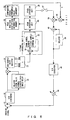
- Fig. 6 shows the configuration of an AFC device in the second preferred embodiment of the present invention.
- an A/D converter 46 converts the signal from analog to digital. Then, the delayer 30 delays the signal by 1,024 samples and calculates a correlation value. The values for 200 samples are sequentially stored in the shift register 31, are added in the adder 32, are averaged by the N frame averaging unit 41. Then, the peak of the correlation value is detected by the peak detection unit 35.
- This preferred embodiment further comprises a comparator 47 and a multiplier 48.
- the comparator 47 judges whether the size of a peak detected in the peak detection is larger than the threshold value. This is because the AFC device may not use a peak value less than the threshold value since the size of a peak becomes less than the threshold value if the size of a peak is greatly affected. Therefore, ⁇ to be added to a control value output from the phase detection unit 36 is multiplied by a weight k.
- k is set to a value close to 1 by setting a normal step value, for example, ⁇ to 1ppm and 0.1ppm at the time of pulling when changing a deviated frequency to a prescribed frequency and at the time of base-station follow-up when being affected by the frequency of the base station, respectively. If the peak value is less than the threshold value, k is set to 0 to stop frequency control.
- a normal step value for example, ⁇ to 1ppm and 0.1ppm
- the control value adjusted thus is converted into analog signals by a D/A converter 49 through a delayer 39 and an adder 40, and is used to control an oscillator 50.
- the output of the oscillator 50 is input to a down-conversion processing unit 45 to down-convert the incoming signal.
- Fig. 7 shows the configuration of an AFC device in the third preferred embodiment of the present invention.
- a threshold value is set for a phase detection value. Specifically, if a large control value is not expected by nature and nevertheless a phase control value larger than the prescribed value is calculated, the control value is left as it previously was since it can be judged that the value is greatly affected by noise.
- phase control value detected in the phase detection unit 36 is sent to a comparator 55 and is compared with the phase threshold value. If the phase control value is less than the threshold value, the phase control value is output without modification to exercise the phase control of the oscillator 50. If the phase control value is larger than the threshold value, it can be judged that the value is greatly affected by noise and that the obtained phase control value should not be used. In this case, the phase control value is set to 0. Specifically, for example, in Fig. 7, k is set to 0.
- Fig. 8 shows the configuration of an AFC device in the fourth preferred embodiment of the present invention.
- This preferred embodiment further comprises a peak position statistical information memory 55 and a comparator (peak position judgment) 56.
- Fig. 9 shows the configuration of an AFC device in the fifth preferred embodiment of the present invention.
- an error signal is sent to a counter 60.
- peak threshold values are compared, judging means is not limited to this, and detected phases or peak positions can also be compared. If an error signal is received a prescribed number, the counter 60 judges that the device is unrecoverable and issues an alarm to request a user (higher layer) to reset his/her receiving device.
- Fig. 10 shows the configuration of an AFC device in the sixth preferred embodiment of the present invention.
- This preferred embodiment further comprises a mode control unit 65 receiving an alarm signal from the counter 60 and automatically resetting the device or automatically performing a synchronization recovery process.
- the mode control unit 65 starts a pulling process in order to re-synchronize the device.
- the unit 65 increases value ⁇ , which is the control step of a control value for the oscillator 50 (for example, changes from 0.1ppm to 1ppm) and an N frame averaging unit 41 decreases the number N of frames to which averaging is applied in order to eliminate noise.
- ⁇ is the control step of a control value for the oscillator 50 (for example, changes from 0.1ppm to 1ppm)
- an N frame averaging unit 41 decreases the number N of frames to which averaging is applied in order to eliminate noise.
- frequency deviation can be rapidly corrected and the frequency can be limited to a desired frequency.
- the pulling process is performed for prescribed hours, an almost desired frequency can be obtained.
- a control step is too large or noise elimination is not sufficient, frequency fluctuations become large.
- a base-station follow-up process (normal frequency control process) is performed. Specifically, value ⁇ is decreased (for example, changed from 1ppm to 0.1ppm) or the number of frames to be averaged of the N frame averaging unit 41 is increased. If value ⁇ is decreased, the fluctuations become small and large frequency fluctuations can be suppressed. If the number of frames to be averaged is increased, noise influence can be reduced and frequency fluctuations can be suppressed.
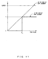
- Figs. 11 and 12 show how to judge the threshold value of a peak value and that of a phase detection value.
- hard judgment e.g., soft judgment
- soft judgment is also applicable. Specifically, an upper limit k upper is set for a value k, and value k can be linearly changed up to the upper limit. Thus, finer control becomes possible.
- Fig. 12 shows the possibility of hard and soft judgment in the case of threshold judgment in a phase detection value, which is the same as with Fig. 11. Therefore, their descriptions are omitted.
- ⁇ is the absolute value of a detected phase.
- Fig. 13 shows selection ranges that can be used for synchronization caputure in an OFDM-CDMA system.
- frequency control can be exercised using the peak correlation value in ranges (1) or (2).
- This means can be applied to an arbitrary OFDM transmission system using one frequency and is not limited to an OFDM-CDMA system.
- Fig. 14 shows the frequency pulling characteristic in the case where the first preferred embodiment is applied.
- a threshold value for the peak value of a correlation value is P th and that a phase fluctuation amount is as follows.
- A(j) and max(A(j) ⁇ are a correlation value and its peak value, respectively.
- Im and Re are an imaginary number part and a real number part, respectively.
- an incoming signal is assumed to be a complex signal.
- Fig. 15 is a graph showing the frequency pulling characteristic in the case where the second preferred embodiment is applied.
- phase fluctuation amount ⁇ is as follows:
- ⁇ th is a phase fluctuation amount expected in anticipated frequency stability.
- a high-accuracy AFC device can be provided in an OFDM system.
- the present invention contributes to the realization of an OFDM-CDMA system, which is considered a strong candidate for the fourth generation mobile communication system.
Landscapes
- Engineering & Computer Science (AREA)
- Computer Networks & Wireless Communication (AREA)
- Signal Processing (AREA)
- Synchronisation In Digital Transmission Systems (AREA)
- Mobile Radio Communication Systems (AREA)
Abstract
An OFDM frequency control device converts an
incoming signal from analog to digital and calculates
a correlation value between the guard interval and data
part from which the guard interval is copied, of the
A/D converted incoming signal. Then, the device averages
such correlation values for the first frame through a
plurality of frames and detects the peak of the averaged
correlation value. Then, by detecting the phase of the
peak position, the device generates the control signal
for an oscillator. The control signal is set in such
a way that a control amount for each time should be a
control step α and is applied to the oscillator.
Furthermore, α is appropriately controlled based on
detected information.
Description
The present invention relates to an automatic
frequency control device in an OFDM (Orthogonal
Frequency Divisional Multiplexing) transmission system
and a method thereof.
Recent advancements in communication
technologies have been remarkable and systems
communicating large amounts of data at high speed have
been being realized. The phenomenon not only applies
to wired communication, but also wireless communication.
Specifically, with the spread of mobile terminals, such
as cellular phones and the like, research and
development has created wireless systems where a large
amount of data can be communicated at high speed, and
multimedia data, such as dynamic images, voice and the
like, can be handled by mobile terminals.
Recently, high-speed wireless communication
based on CDMA called "the third generation" has been
developed and is about to be put into practical use.
In response to this trend, wireless communication R&D
departments have started to research and develop the
fourth generation wireless communication system aiming
at larger-capacity and higher-speed wireless
communication.
OFDM-CDMA is a strong candidate for the basic
system of the fourth generation mobile communication
system. In this system, an OFDM technology for
transmitting a plurality of pieces of information in
parallel using a plurality of sub-carriers each with
a reciprocally orthogonal frequency and a CDMA
technology using the orthogonality of a spread code by
which user data is multiplied when a plurality of pieces
of user data are multiplexed, are united in order to
realize larger-capacity, higher-quality and
higher-speed communication.
However, currently the OFDM-CDMA system is still
in a proposal stage and in an R&D evaluation stage, and
individual technologies required for an actual system
must still be developed.
In particular, in a system based on multi-carrier
transmission, such as an OFDM-CDMA system and the like,
it is important to reproduce a prescribed carrier
frequency in a receiver. In particular, the control
accuracy of a reproduced carrier frequency is very
important.
An object of the present invention is to provide
an OFDM automatic frequency control device with an
excellent frequency control function and a method
thereof.
The automatic frequency control device of the
present invention is one in an OFDM (Orthogonal
Frequency Divisional Multiplexing) system. The
automatic frequency control device comprises
correlation means for calculating a correlation value
between the guard interval and data of an incoming signal,
averaging means for averaging the correlation values
across a plurality of symbols and a plurality of frames,
peak position detecting means for detecting the peak
position of the averaged correlation value and control
means for controlling an oscillator using a prescribed
step, based on the detected peak position.
The automatic frequency control method of the
present invention is OFDM (Orthogonal Frequency
Divisional Multiplexing). The automatic frequency
control method comprises calculating a correlation
value between the guard interval and data of an incoming
signal (correlation step), averaging the correlation
values across a plurality of symbols and a plurality
of frames (averaging step), detecting the peak position
of the averaged correlation value (peak position
detecting step) and controlling an oscillator using a
prescribed step, based on the detected peak position
(control execution step).
According to the present invention, in an OFDM
system, since the receiver's oscillator can rapidly,
efficiently and accurately control the frequency,
signals can be received with high-accuracy.
Fig. 1 shows the basic configuration of the
transmitter of an OFDM-CDMA system.
Input user data is, for example, QPSK-modulated
by a QPSK modulation mapping unit 1. This modulation
method is one example, and modulation is not necessarily
limited to QPSK. The modulated user data is converted
from serial into parallel by a serial/parallel converter
2. For example, one symbol of the user data modulated
for one time slot is output to the output a1 of the
serial/parallel converter 2. Similarly, one symbol of
the user data modulated in the same timing is output
to the outputs a2 through an of serial/parallel
converters 2.
Such sn modulation signal symbols output from the
serial/parallel converter 2 thus are copied by a copying
unit 3 provided for each output. Then, each of the sn
modulation signal symbols is multiplied by each chip
of a spread code (in this case, a Walsh code) in a
multiplier 4. In this case, the length of a Walsh code
equals sn chips. Therefore, each of sn copied modulation
signal symbols is multiplied by a different chip of the
sn chips of a Walsh code.
Then, each of the modulation signal symbols that
are multiplied by such a Walsh code is further multiplied
by a spread code (in this case, a Gold series code) in
a multiplier 5. Then, a plurality of pieces of other
user data transmitted from a modulation unit 7 for other
users are modulated. Such signals processed in the same
way are added in an adder 6 and are input to an IFFT
(Inverse Fast Fourier Transformation) unit 8.
Each signal input to the IFFT unit 8 is regarded
to be each frequency component, inverse Fourier
transformation is applied to each signal and each signal
is output as one modulation wave. Specifically, if the
number of inputs to the IFFT unit 8 is 1,024, the number
of frequency components is 1,024. Therefore, each
frequency component is carried on each of 1,024
sub-carriers. Then, the components are combined and are
output from the IFFT unit 8.
The IFFT unit 8 performs Fourier transformation
using a sub-carrier with a fundamental frequency and
a sub-carrier with a frequency obtained by multiplying
the fundamental frequency by an integer. If the
frequency of each sub-carrier can be obtained by
multiplying the fundamental frequency by an integer,
an integration of the product of the sub-carrier with
a frequency obtained by multiplying the fundamental
frequency by an integer and that with the fundamental
frequency for one cycle, becomes 0 and only an
integration of the product of sub-carriers with the same
frequency for one cycle becomes a finite value. In other
words, a sub-carrier with a specific frequency is
orthogonal to a sub-carrier with a frequency obtained
by multiplying the fundamental frequency by an integer.
The word "orthogonal" in OFDM derives from this fact.
Thus, in a guard interval adding unit (+GI unit)
9, a guard interval, which is described later, is added
to each signal wave output from the IFFT unit 8, and
the signal waves each with a guard interval are
transmitted. Up to this point, data are digitally
processed. In a D/A converter 10, digital signals are
converted into analog signals and transmitted to a
transmission side.
Fig. 2 shows how each modulation signal symbol is
allocated according to sub-carrier and time slots, being
the vertical and horizontal axes, respectively.
A modulation signal is packed into a frame. The
frame is composed of at least a data section and a pilot
section. In this example, the number of sub-carriers
is 1,024. It is assumed that a Walsh code is composed
of 32 chips. In this case, if it is assumed that the
data section is composed of time slots 1 through 4, in
the data unit, one symbol is stored in each of
sub-carriers 1 through 32 and another is in sub-carriers
33 through 64 of time slot 1, etc., and one time slot
accommodates 32 (=1,024/32) symbols.
Although a subsequent time slot 2 accommodates
symbols similarly, the multiplication methods of a Wash
code and a Gold series code are different from those
of time slot 1. Specifically, 1,024 chips of a code is
generated by combining Walsh codes with Gold series
codes. Then, for example, as shown in Fig. 2, in time
slot 2, symbols are multiplied after a generated code
is shifted by eight chips. In time slot 3, symbols are
multiplied after the generated code is shifted by eight
more chips. In time slot 4, symbols are multiplied after
the generated code is shifted by another eight more chips.
Thus, the multiplication timing of a spread code is
shifted eight chips.
So far, the relation between the symbol array and
spread codes in a data section has been described. The
pilot section has a different structure from that of
the data section. For example, if a time slot n
accommodates one symbol of the pilot section, this pilot
symbol is commonly accommodated for 1, 024 sub-carriers.
Although one frame accommodates, for example, four pilot
symbols, which is described later, each symbol is
multiplied in the same way. The Walsh code
multiplication method of the pilot section is different
from that of the data section, which is described later.
Fig. 3 shows the basic configuration of the
receiver of an OFDM-CDMA system.
Incoming data is first converted into digital
signals by an A/D converter 15. Then, in a guard interval
eliminating unit (-GI unit) 16, guard intervals are
eliminated, and the resulting digital signals are input
to an FFT (Fast Fourier Transformation) unit 17. The
FFT unit 17 decomposes a signal wave for a specific time
period into its frequency components by Fourier
transformation. Specifically, although in a
transmitter, the modulation signal symbol of user data
is regarded to be frequency components and is converted
into a signal wave for a specific time period by
inverse-Fourier transformation, in the FFT unit 17,
frequency components are extracted from a signal wave
for a specific time period by Fourier transformation.
That is, in this case, the modulation signal symbol of
user data is extracted.
The modulation signal symbol of the pilot section
of the frequency components f1 through fn obtained by
the process of the FFT unit 17 is used to calculate a
channel prediction in a channel prediction unit 18. In
a channel compensation unit 19, the channel of each of
the frequency components f1 through fn is compensated
for. Then, in a multiplier 20, each of the frequency
components f1 through fn is multiplied by the complex
conjugate of the Gold series code used on a transmitting
side. Then, in a multiplier 21, each of the frequency
components f1 through fn is multiplied by a Walsh code.
In this stage, the modulation signal symbol of the user
data is demodulated, signals including one symbol are
added in an adder 22, and the value of the symbol is
judged by a symbol judger 23. Then, the judged symbol
value is converted from parallel to serial by a
parallel/serial converter 24 and is input to a
demodulation demapping unit 25. In the demodulation
demapping unit 25, the user data modulated by the
transmitter is demodulated and extracted. Then, the user
data is transmitted to a receiving unit.
Fig. 4 shows a guard interval.
The top section of data of a prescribed length is
copied and attached to the end section of a data
transmitted from a transmitter as a guard interval (GI) .
The length of the guard interval is determined in such
a way that the delay of a wave that has been delayed
due to multi-path and the like and reaches a receiver
can be accommodated in this guard interval.
The reason why such a guard interval is provided
is as follows.
Specifically, data and a guard interval are
carried and transmitted on a plurality of sub-carriers.
However, if attention is focused onto one sub-carrier,
data to which Fourier transformation has been applied
once is accommodated in one cycle of a sub-carrier with
the fundamental frequency or in a cycle of a sub-carrier
with a frequency obtained by multiplying the fundamental
frequency by an integer. In Fourier transformation, if
each frequency component is extracted, the fact that
in one cycle of the fundamental frequency, sub-carriers
are orthogonal to one another, is used. Therefore, in
order to correctly extract each frequency component,
the data of a received signal to which Fourier
transformation is applied must be carried in a cycle
of a sub-carrier with a frequency obtained by
multiplying the fundamental frequency by an integer.
Otherwise, orthogonality between sub-carriers will be
destroyed. In this case, if Fourier transformation is
applied, a correct value cannot be obtained.
In particular, if a delay wave is received due to
multi-path and the like, as shown in Fig. 4, the data
of a wave is delayed and arrives later than the data
of a direct wave. Therefore, if Fourier transformation
is applied to the shaded part shown in Fig. 4 when
subsequent data follows immediately after,
inter-symbol interference (ISI) occurs.
In this case, as shown in Fig. 4, if a guard
interval is added, a sub-carrier for carrying the guard
interval is continuously connected to the end section
of data, and the data is expanded by the guard interval,
since the guard interval is the copy of the top section
of the data of a prescribed length. If the delay wave
reaches the receiver within a delay time covered by the
length of a guard interval, the Fourier transformation
of both the direct and delay waves is performed in one
cycle of the fundamental frequency. Therefore, a correct
value can be obtained. Since another piece of data
follows immediately after the data, there is no
inter-symbol interference. Although the result of
Fourier transformation of data including the delayed
wave includes amplitude change and phase rotation, they
are to be predicted and compensated for by channel
prediction and channel compensation, respectively.
As described above, by providing a guard interval,
the result of Fourier transformation is compensated for
and inter-symbol interference can be prevented even if
there is a delay.
Fig. 5 shows the configuration of an AFC device
in the first preferred embodiment of the present
invention.
Although with reference to Fig. 1, it is described
that the output from the IFFT unit has been converted
from digital to analog, in reality, afterwards the
frequency of a signal is upconverted into a carrier
frequency at an analog signal level. Therefore, an
incoming signal must be downconverted by the receiver
depending on the carrier frequency and must be converted
from analog to digital. This preferred embodiment is
used to exercise frequency control through receiver's
local oscillator for the purpose of this
down-conversion.
Although this preferred embodiment is described
presuming an OFDM-CDMA system, the present invention
is applicable to any system based on an OFDM system,
for example, an OFDM-CDMA system.
In an AFC (Automatic Frequency Control) device,
an A/D-converted incoming signal is input to a digital
signal processing unit. Therefore, only the digital
signal processing unit is described. A delayer 30 delays
an input signal in order to adjust the beginning of the
symbol of an OFDM system which is composed of a guard
interval and data, from which a guard interval is copied,
to the guard interval, and multiplies the signal by the
original symbol. In this example, it is assumed that
one symbol is composed of data of 1,024 samples and a
guard interval of 200 samples. Therefore, if data is
input in order to make the start point of multiplication
between the first 200 samples of one symbol data and
the guard interval of 200 samples which is added 1024
samples back from the head of one symbol coincide, the
delayer 30 delays the data by 1,024 samples and
multiplies the data by data input later by 1,024 samples.
The results of the multiplication, that is,
correlation operation are sequentially stored in a shift
register 31 of the length of the guard interval, that
is, 200 samples and are added in an adder 32. The result
of the addition is input to an N frame averaging unit
41 comprising an OFDM symbol length storage unit 33 and
an adder 34.
1,224 samples obtained by adding data and guard
intervals, which are sample data for one symbol, are
stored in the OFDM symbol length storage unit 33, and
noise influences are eliminated by averaging
correlation values of symbols sequentially input.
Therefore, the N frame averaging unit 41 performs
addition for each symbol in a frame composed of 32
symbols and addition of N frames. Therefore, the unit
41 performs 32×N additions in total.
In a peak detection unit 35, peak detection is
applied to the correlation value averaged by the N frame
averaging unit 41. Then, in a phase detection unit 36,
it is detected on which sample a peak position falls,
and a control value to be used to correct the frequency
deviation of the oscillator of a receiver is output.
The control value is input to a multiplier 38
through a switch 37 every time a peak is detected. In
the multiplier 38, the control value is multiplied by
α specifying a control step width so that the control
value may not suddenly exercise great frequency control
over the oscillator. In other words, the value may only
gradually exercise frequency control over the
oscillator. α is a prescribed value meeting a condition
of 0<α<1.
Thus, the control value obtained by multiplying
α is delayed by an adder 40 and a delayer 39 in order
to realize a control method of adding the current control
value to the previous control value, the current control
value is added to the previous control value, and the
added value is transmitted as a control signal. The
control signal is D/A-converted and is used to control
the oscillator.
The present invention realizes frequency
stability by averaging the guard interval correlation
values in one symbol between frames and increasing an
S/N ratio. However, since signals fluctuate due to
fading as time elapses when they are received by a mobile
terminal, the lower the maximum Doppler frequency that
most contributes to this, the less the fading
suppression effect by averaging, and the greater the
degradation of a receiving characteristic.
Therefore, if the maximum Doppler frequency is low
or if an S/N ratio is low, a noise component can be
detected as a peak and a phase fluctuation amount with
great error can be output since an S/N ratio obtained
within an average number of frames can be insufficient.
In particular, in the latter case, S/N degradation due
to shadowing is assumed. Since a large amount of
frequency control is caused by this phenomenon,
frequency stability may be reduced at both the time of
initial pulling and base-station follow-up.
A stable method that is not affected by noise, for
solving this problem by setting a threshold value for
an S/N ratio obtained within the average number of frames
and not exercising frequency control if the S/N ratio
is less than the threshold value, is shown below.
Fig. 6 shows the configuration of an AFC device
in the second preferred embodiment of the present
invention.
In Fig. 6, the same reference numbers are attached
to the same components as those shown in Fig. 5, and
their descriptions are omitted.
On receipt of an incoming signal, an A/D converter
46 converts the signal from analog to digital. Then,
the delayer 30 delays the signal by 1,024 samples and
calculates a correlation value. The values for 200
samples are sequentially stored in the shift register
31, are added in the adder 32, are averaged by the N
frame averaging unit 41. Then, the peak of the
correlation value is detected by the peak detection unit
35.
This preferred embodiment further comprises a
comparator 47 and a multiplier 48. The comparator 47
judges whether the size of a peak detected in the peak
detection is larger than the threshold value. This is
because the AFC device may not use a peak value less
than the threshold value since the size of a peak becomes
less than the threshold value if the size of a peak is
greatly affected. Therefore, α to be added to a control
value output from the phase detection unit 36 is
multiplied by a weight k. If the peak value is larger
than the threshold value, k is set to a value close to
1 by setting a normal step value, for example, α to 1ppm
and 0.1ppm at the time of pulling when changing a
deviated frequency to a prescribed frequency and at the
time of base-station follow-up when being affected by
the frequency of the base station, respectively. If the
peak value is less than the threshold value, k is set
to 0 to stop frequency control.
The control value adjusted thus is converted into
analog signals by a D/A converter 49 through a delayer
39 and an adder 40, and is used to control an oscillator
50.
The output of the oscillator 50 is input to a
down-conversion processing unit 45 to down-convert the
incoming signal.
Fig. 7 shows the configuration of an AFC device
in the third preferred embodiment of the present
invention.
In this preferred embodiment, a threshold value
is set for a phase detection value. Specifically, if
a large control value is not expected by nature and
nevertheless a phase control value larger than the
prescribed value is calculated, the control value is
left as it previously was since it can be judged that
the value is greatly affected by noise.
In Fig. 7, the same reference numbers are attached
to the same components as those shown in Fig. 6, and
their descriptions are omitted.
The phase control value detected in the phase
detection unit 36 is sent to a comparator 55 and is
compared with the phase threshold value. If the phase
control value is less than the threshold value, the phase
control value is output without modification to exercise
the phase control of the oscillator 50. If the phase
control value is larger than the threshold value, it
can be judged that the value is greatly affected by noise
and that the obtained phase control value should not
be used. In this case, the phase control value is set
to 0. Specifically, for example, in Fig. 7, k is set
to 0.
Fig. 8 shows the configuration of an AFC device
in the fourth preferred embodiment of the present
invention.
In Fig. 8, the same reference numbers are attached
to the same components as those shown in Fig. 7, and
their descriptions are omitted.
This preferred embodiment further comprises a
peak position statistical information memory 55 and a
comparator (peak position judgment) 56. The peak
position statistical information memory 55 stores peak
positions sent from the peak detection unit 35 each time
and memorizes how many peaks are located at any position.
If the peak detection unit 35 judges that the detected
peak position is abnormal, based on the statistical
information of peak positions stored in the peak
position statistical information memory 55, the
comparator 56 detects this and prevents the oscillator
50 from being controlled, for example, by setting k to
0 (k=0) . This is because it can be judged that the peak
position has been greatly affected by noise and the
oscillator 50 can be correctly controlled, based on the
fact that the peak position is statistically abnormal.
Fig. 9 shows the configuration of an AFC device
in the fifth preferred embodiment of the present
invention.
In Fig. 9, the same reference numbers are attached
to the same components as those shown in Fig. 6, and
their descriptions are omitted.
In this preferred embodiment, if as a result of
the threshold value judgment of a comparator, a peak
position with unexpectedly large error is detected, an
error signal is sent to a counter 60. Although in Fig.
9 peak threshold values are compared, judging means is
not limited to this, and detected phases or peak
positions can also be compared. If an error signal is
received a prescribed number, the counter 60 judges that
the device is unrecoverable and issues an alarm to
request a user (higher layer) to reset his/her receiving
device.
This is because the device must be reset and
synchronized again if the synchronization of the device
is completely destroyed due to the failure of a receiver
or transmitter.
Fig. 10 shows the configuration of an AFC device
in the sixth preferred embodiment of the present
invention.
In Fig. 10, the same reference numbers are
attached to the same components as those shown in Fig.
9, and their descriptions are omitted. The judging means
is not limited as with Fig. 9.
This preferred embodiment further comprises a
mode control unit 65 receiving an alarm signal from the
counter 60 and automatically resetting the device or
automatically performing a synchronization recovery
process. The mode control unit 65 starts a pulling
process in order to re-synchronize the device.
Specifically, the unit 65 increases value α, which is
the control step of a control value for the oscillator
50 (for example, changes from 0.1ppm to 1ppm) and an
N frame averaging unit 41 decreases the number N of
frames to which averaging is applied in order to
eliminate noise. Thus, frequency deviation can be
rapidly corrected and the frequency can be limited to
a desired frequency. Although the pulling process is
performed for prescribed hours, an almost desired
frequency can be obtained. However, for the reason that
a control step is too large or noise elimination is not
sufficient, frequency fluctuations become large.
Therefore, after the pulling process is performed for
prescribed hours, a base-station follow-up process
(normal frequency control process) is performed.
Specifically, value α is decreased (for example,
changed from 1ppm to 0.1ppm) or the number of frames
to be averaged of the N frame averaging unit 41 is
increased. If value α is decreased, the fluctuations
become small and large frequency fluctuations can be
suppressed. If the number of frames to be averaged is
increased, noise influence can be reduced and frequency
fluctuations can be suppressed.
Figs. 11 and 12 show how to judge the threshold
value of a peak value and that of a phase detection value.
As shown in Fig. 11, in the preferred embodiments
described above, if a peak value is greater than the
threshold value, k is set to 1 (k=1) . If a peak value
is less than the threshold value, k is set to 0 (k=0) .
This is called "hard judgment". However, soft judgment
is also applicable. Specifically, an upper limit kupper
is set for a value k, and value k can be linearly changed
up to the upper limit. Thus, finer control becomes
possible. Similarly, Fig. 12 shows the possibility of
hard and soft judgment in the case of threshold judgment
in a phase detection value, which is the same as with
Fig. 11. Therefore, their descriptions are omitted.
However, in this case, Δ is the absolute value
of a detected phase.
Fig. 13 shows selection ranges that can be used
for synchronization caputure in an OFDM-CDMA system.
In an OFDM-CDMA system, electric waves with the
same frequency are transmitted from a plurality of
different stations. Therefore, if synchronization
capture is applied by the receiver, and the peak of a
correlation value is detected as described above, there
is a possibility that a plurality of peaks may appear
at different positions. However, since all base stations
transmit electric waves with the same frequency,
frequency setting can be performed using the electric
wave of any base station.
Therefore, if there are two peaks as shown in Figs.
13A and 13B, frequency control can be exercised using
the peak correlation value in ranges (1) or (2). This
means can be applied to an arbitrary OFDM transmission
system using one frequency and is not limited to an
OFDM-CDMA system.
Fig. 14 shows the frequency pulling
characteristic in the case where the first preferred
embodiment is applied.
In Fig. 14, it is assumed that a threshold value
for the peak value of a correlation value is Pth and that
a phase fluctuation amount is as follows.
 In the equation, A(j) and max(A(j)} are a correlation
value and its peak value, respectively. Im and Re are
an imaginary number part and a real number part,
respectively. Specifically, an incoming signal is
assumed to be a complex signal. If the expected mean
of peak values is Pav, threshold value Pth is assumed to
be as follows:
In the equation, A(j) and max(A(j)} are a correlation
value and its peak value, respectively. Im and Re are
an imaginary number part and a real number part,
respectively. Specifically, an incoming signal is
assumed to be a complex signal. If the expected mean
of peak values is Pav, threshold value Pth is assumed to
be as follows:
Pth = βPav
Fig. 14 shows the frequency pulling
characteristics in the case where β = 0.25, where β =
0.5 and where no threshold value is used, under the
conditions described above. In the case where no
threshold value is used, a large frequency residual
occurs at the 11th to 12th second, while when a threshold
value is used, there is no such large frequency
fluctuation and frequency is stably controlled.
Fig. 15 is a graph showing the frequency pulling
characteristic in the case where the second preferred
embodiment is applied.
In this case, if a threshold value for phase
fluctuation amount is th, phase fluctuation amount Δ
is as follows:

In the equation, th is a phase fluctuation amount
expected in anticipated frequency stability.
Fig. 15 shows the frequency pulling
characteristics in the case where th = 47°, where th
= 23.5° and where no threshold value is used. In each
case, a large frequency change shown at the 11th to 12th
second is suppressed and frequency is stabilized.
According to the present invention, a
high-accuracy AFC device can be provided in an OFDM
system. In particular, the present invention
contributes to the realization of an OFDM-CDMA system,
which is considered a strong candidate for the fourth
generation mobile communication system.
Claims (22)
- An automatic frequency control device in an OFDM (Orthogonal Frequency Divisional Multiplexing) system, comprising:correlation means for calculating a correlation value between a guard interval and data of an incoming signal;averaging means for averaging correlation values across a plurality of symbols and a plurality of frames;peak position detecting means for detecting a peak position of the averaged correlation value; andcontrol means for controlling an oscillator using a prescribed step, based on the detected peak position.
- The automatic frequency control device according to claim 1, wherein if a peak value of the correlation value is less than a prescribed value, the oscillator is not controlled.
- The automatic frequency control device according to claim 1, wherein if a phase fluctuation amount obtained from the peak position of the correlation value is greater than a prescribed value, a control value of the oscillator is not updated.
- The automatic frequency control device according to claim 1, wherein if the peak position of the correlation value is judged to be abnormal, based on statistical information of peak positions previously obtained, the oscillator is not controlled.
- The automatic frequency control device according to claim 1, wherein if the number of detected peak positions with error greater than expected exceeds a prescribed number, an alarm is sent to a user or a higher layer to prompt control of the automatic frequency control device.
- The automatic frequency control device according to claim 1, wherein if the number of detected peak positions with error greater than expected exceeds a prescribed number, the number of frames to be averaged and the width of the control step of a correlation value are modified.
- The automatic frequency control device according to claim 1, wherein the control step based on the peak value of a correlation value smoothly changes against change of the peak value.
- The automatic frequency control device according to claim 1, wherein the control step based on the phase fluctuation amount obtained from the peak position of a correlation value smoothly changes against change of phase fluctuation amount.
- The automatic frequency control device according to claim 1, wherein the number of frames to be averaged at the time of initial pulling and that at the time of base-station follow-up are different.
- The automatic frequency control device according to claim 1, wherein the control step at the time of initial pulling and that at the time of base-station follow-up are different.
- The automatic frequency control device according to claim 1, which is used in an OFDM-CDMA system.
- An automatic frequency control method in an OFDM (Orthogonal Frequency Divisional Multiplexing) system, comprising the steps of:calculating a correlation value between a guard interval and data of an incoming signal;averaging correlation values across a plurality of symbols and a plurality of frames;detecting a peak position of the averaged correlation value; andcontrolling an oscillator using a prescribed step, based on the detected peak position.
- The automatic frequency control method according to claim 12, wherein if a peak value of the correlation value is less than a prescribed value, the oscillator is not controlled.
- The automatic frequency control method according to claim 12, wherein if a phase fluctuation amount obtained from the peak position of the correlation value is greater than a prescribed value, a control value of the oscillator is not updated.
- The automatic frequency control method according to claim 12, wherein if the peak position of the correlation value is judged to be abnormal based on statistical information of peak positions previously obtained, the oscillator is not controlled.
- The automatic frequency control method according to claim 12, wherein if the number of detected peak positions with error greater than expected exceeds a prescribed number, an alarm is sent to a user or a higher layer to prompt control of the automatic frequency control device.
- The automatic frequency control method according to claim 12, wherein if the number of detected peak positions with error greater than expected exceeds a prescribed number, the number of frames to be averaged and the width of the control step of a correlation value are modified.
- The automatic frequency control device according to claim 12, wherein the control step based on the peak value of a correlation value smoothly changes against change of the peak value.
- The automatic frequency control device according to claim 12, wherein the control step based on the phase fluctuation amount obtained from the peak position of a correlation value smoothly changes against change of phase fluctuation amount.
- The automatic frequency control device according to claim 12, wherein the number of frames to be averaged at the time of initial pulling and that at the time of base-station follow-up are different.
- The automatic frequency control method according to claim 12, wherein the control step at the time of initial pulling and that at the time of base-station follow-up are different.
- The automatic frequency control method according to claim 12, which is used in an OFDM-CDMA system.
Applications Claiming Priority (1)
| Application Number | Priority Date | Filing Date | Title |
|---|---|---|---|
| PCT/JP2001/008542 WO2003032543A1 (en) | 2001-09-28 | 2001-09-28 | Automatic frequency control device for ofdm and method therefor |
Publications (2)
| Publication Number | Publication Date |
|---|---|
| EP1432162A1 true EP1432162A1 (en) | 2004-06-23 |
| EP1432162A4 EP1432162A4 (en) | 2010-04-07 |
Family
ID=11737779
Family Applications (1)
| Application Number | Title | Priority Date | Filing Date |
|---|---|---|---|
| EP01972584A Withdrawn EP1432162A4 (en) | 2001-09-28 | 2001-09-28 | OFDM AUTOMATIC FREQUENCY CONTROL DEVICE AND ASSOCIATED METHOD |
Country Status (4)
| Country | Link |
|---|---|
| US (1) | US7474610B2 (en) |
| EP (1) | EP1432162A4 (en) |
| JP (1) | JPWO2003032543A1 (en) |
| WO (1) | WO2003032543A1 (en) |
Families Citing this family (6)
| Publication number | Priority date | Publication date | Assignee | Title |
|---|---|---|---|---|
| US20050135457A1 (en) * | 2003-12-19 | 2005-06-23 | Molisch Andreas F. | Ultra wide bandwidth transmitter with tone grouping and spreading |
| EP1841112B1 (en) * | 2005-01-18 | 2014-06-04 | Fujitsu Limited | Transmitting method and transmitting apparatus in ofdm-cdma communication system |
| JP4755077B2 (en) * | 2006-12-22 | 2011-08-24 | 富士通セミコンダクター株式会社 | Transmission mode, guard length detection circuit and method |
| WO2009040739A2 (en) * | 2007-09-28 | 2009-04-02 | Nokia Corporation | System and method for improving signaling channel robustness |
| US8472309B2 (en) * | 2008-08-20 | 2013-06-25 | Qualcomm Incorporated | Using CDMA to send uplink signals in WLANs |
| US8559569B1 (en) * | 2011-01-28 | 2013-10-15 | Marvell International Ltd. | Preamble detection based on repeated preamble codes |
Family Cites Families (14)
| Publication number | Priority date | Publication date | Assignee | Title |
|---|---|---|---|---|
| JPH04175016A (en) * | 1990-11-08 | 1992-06-23 | Toshiba Corp | Radio communication equipment |
| JPH0774726A (en) * | 1993-09-03 | 1995-03-17 | Sony Corp | Demodulator |
| JP3041171B2 (en) * | 1993-09-28 | 2000-05-15 | 株式会社東芝 | OFDM reception synchronization circuit |
| JP3074103B2 (en) * | 1993-11-16 | 2000-08-07 | 株式会社東芝 | OFDM synchronous demodulation circuit |
| JPH07297779A (en) * | 1994-04-26 | 1995-11-10 | Toshiba Corp | Digital radio with automatic frequency control function |
| JP3130752B2 (en) * | 1995-02-24 | 2001-01-31 | 株式会社東芝 | OFDM transmission receiving method and transmitting / receiving apparatus |
| SE514986C2 (en) * | 1995-03-01 | 2001-05-28 | Telia Ab | Method and device for synchronization with OFDM systems |
| JPH098702A (en) * | 1995-06-23 | 1997-01-10 | Fujitsu Ltd | Spread spectrum receiver |
| JP2818148B2 (en) * | 1996-08-23 | 1998-10-30 | 株式会社次世代デジタルテレビジョン放送システム研究所 | OFDM demodulator |
| JP3507657B2 (en) * | 1997-05-16 | 2004-03-15 | シャープ株式会社 | Orthogonal frequency division multiplexing demodulator |
| KR100335443B1 (en) * | 1999-06-15 | 2002-05-04 | 윤종용 | Symbol timing and frequency synchronizing device for OFDM signals and method thereof |
| JP3631086B2 (en) * | 2000-02-23 | 2005-03-23 | 株式会社エヌ・ティ・ティ・ドコモ | Multi-carrier CDMA radio transmission method and apparatus |
| JP4356203B2 (en) * | 2000-07-11 | 2009-11-04 | ソニー株式会社 | Demodulator and demodulation method |
| US20030063678A1 (en) * | 2001-08-21 | 2003-04-03 | Crawford James A. | OFDM pilot tone tracking to reduce performance loss due to frequency pulling and pushing |
-
2001
- 2001-09-28 EP EP01972584A patent/EP1432162A4/en not_active Withdrawn
- 2001-09-28 JP JP2003535382A patent/JPWO2003032543A1/en active Pending
- 2001-09-28 WO PCT/JP2001/008542 patent/WO2003032543A1/en not_active Ceased
-
2004
- 2004-03-11 US US10/799,937 patent/US7474610B2/en not_active Expired - Fee Related
Also Published As
| Publication number | Publication date |
|---|---|
| EP1432162A4 (en) | 2010-04-07 |
| US7474610B2 (en) | 2009-01-06 |
| WO2003032543A1 (en) | 2003-04-17 |
| JPWO2003032543A1 (en) | 2005-01-27 |
| US20040174811A1 (en) | 2004-09-09 |
Similar Documents
| Publication | Publication Date | Title |
|---|---|---|
| US6714511B1 (en) | OFDM transmission/reception apparatus having a guard interval length changing function | |
| US7251282B2 (en) | Receiver and method to detect and synchronize with a symbol boundary of an OFDM symbol | |
| US7672277B2 (en) | Method and device for estimating carrier frequency offset of subscriber terminal | |
| US7336597B2 (en) | System and method for two channel frequency offset estimation of OFDM signals | |
| US7991084B2 (en) | Apparatus, method and computer program product for detecting non-synchronized random access channel preamble | |
| US7058006B2 (en) | OFDM communication apparatus | |
| EP1063824A2 (en) | Symbol synchronisation in multicarrier receivers | |
| US20060018250A1 (en) | Apparatus and method for transmitting and receiving a signal in an orthogonal frequency division multiplexing system | |
| US7649964B2 (en) | Radio receiver and noise estimated value correction method | |
| JP4043287B2 (en) | Wireless communication system, communication apparatus, and reception quality measuring method | |
| US20050141641A1 (en) | Receiving method and receiving apparatus with adaptive array signal processing | |
| US7474610B2 (en) | OFDM automatic frequency control device and method thereof | |
| US6944119B1 (en) | OFDM receiving apparatus, OFDM transmission apparatus and OFDM communication method | |
| US20060120487A1 (en) | Frequency offset estimating method and frequency offset correcting apparatus utilizing said method | |
| US20070274421A1 (en) | Method and apparatus for frequency tracking in a space time transmit diversity receiver | |
| WO2002007403A1 (en) | Channel presuming system and channel presuming method | |
| JP2001345780A (en) | OFDM receiver using maximum ratio combining diversity | |
| JP2001345778A (en) | OFDM reception signal synchronizer using diversity | |
| US7916773B2 (en) | Scaling and truncating in a receiver for coded digital data symbols | |
| JP5023091B2 (en) | OFDM transmitter, OFDM receiver and OFDM transmission method | |
| Watanabe et al. | Burst synchronization scheme for millimeter band OFDM | |
| JP2004166121A (en) | Synchronous tracking device and method | |
| HK1091055B (en) | System and method for two channel frequency offset estimation of ofdm signals | |
| HK1091055A (en) | System and method for two channel frequency offset estimation of ofdm signals | |
| JP2007037195A (en) | OFDM transmitter and OFDM transmission method |
Legal Events
| Date | Code | Title | Description |
|---|---|---|---|
| PUAI | Public reference made under article 153(3) epc to a published international application that has entered the european phase |
Free format text: ORIGINAL CODE: 0009012 |
|
| 17P | Request for examination filed |
Effective date: 20040419 |
|
| AK | Designated contracting states |
Kind code of ref document: A1 Designated state(s): DE FR GB IT |
|
| A4 | Supplementary search report drawn up and despatched |
Effective date: 20100304 |
|
| RIC1 | Information provided on ipc code assigned before grant |
Ipc: H04L 27/26 20060101AFI20100226BHEP Ipc: H04J 11/00 20060101ALI20100226BHEP |
|
| STAA | Information on the status of an ep patent application or granted ep patent |
Free format text: STATUS: THE APPLICATION IS DEEMED TO BE WITHDRAWN |
|
| 18D | Application deemed to be withdrawn |
Effective date: 20100525 |