EP1432052A1 - Vorrichtung zur Montage von einer Energiequelle für tragbares elektronisches Gerät - Google Patents
Vorrichtung zur Montage von einer Energiequelle für tragbares elektronisches Gerät Download PDFInfo
- Publication number
- EP1432052A1 EP1432052A1 EP02028484A EP02028484A EP1432052A1 EP 1432052 A1 EP1432052 A1 EP 1432052A1 EP 02028484 A EP02028484 A EP 02028484A EP 02028484 A EP02028484 A EP 02028484A EP 1432052 A1 EP1432052 A1 EP 1432052A1
- Authority
- EP
- European Patent Office
- Prior art keywords
- housing
- energy source
- mounting device
- battery
- cover
- Prior art date
- Legal status (The legal status is an assumption and is not a legal conclusion. Google has not performed a legal analysis and makes no representation as to the accuracy of the status listed.)
- Granted
Links
- 210000002105 tongue Anatomy 0.000 claims abstract description 34
- 238000000034 method Methods 0.000 claims abstract description 4
- 239000011324 bead Substances 0.000 claims description 15
- 238000003780 insertion Methods 0.000 claims description 5
- 230000037431 insertion Effects 0.000 claims description 5
- 239000004020 conductor Substances 0.000 claims description 4
- 238000000151 deposition Methods 0.000 claims description 4
- 230000000717 retained effect Effects 0.000 claims description 4
- 238000007789 sealing Methods 0.000 claims description 3
- 239000012777 electrically insulating material Substances 0.000 claims 1
- 238000010137 moulding (plastic) Methods 0.000 claims 1
- 238000003825 pressing Methods 0.000 abstract description 2
- 125000006850 spacer group Chemical group 0.000 description 10
- 230000014759 maintenance of location Effects 0.000 description 9
- 239000000463 material Substances 0.000 description 8
- 230000035939 shock Effects 0.000 description 5
- 230000004308 accommodation Effects 0.000 description 4
- 230000005489 elastic deformation Effects 0.000 description 4
- 238000000465 moulding Methods 0.000 description 3
- 230000000903 blocking effect Effects 0.000 description 2
- 230000002093 peripheral effect Effects 0.000 description 2
- 229910001369 Brass Inorganic materials 0.000 description 1
- RYGMFSIKBFXOCR-UHFFFAOYSA-N Copper Chemical compound [Cu] RYGMFSIKBFXOCR-UHFFFAOYSA-N 0.000 description 1
- 239000010951 brass Substances 0.000 description 1
- 230000006835 compression Effects 0.000 description 1
- 238000007906 compression Methods 0.000 description 1
- 229910052802 copper Inorganic materials 0.000 description 1
- 239000010949 copper Substances 0.000 description 1
- 238000005520 cutting process Methods 0.000 description 1
- 238000009434 installation Methods 0.000 description 1
- 238000004519 manufacturing process Methods 0.000 description 1
- 239000002184 metal Substances 0.000 description 1
- 229910052751 metal Inorganic materials 0.000 description 1
- 229910001092 metal group alloy Inorganic materials 0.000 description 1
- 239000007769 metal material Substances 0.000 description 1
- 210000000707 wrist Anatomy 0.000 description 1
Images


Classifications
-
- G—PHYSICS
- G04—HOROLOGY
- G04C—ELECTROMECHANICAL CLOCKS OR WATCHES
- G04C10/00—Arrangements of electric power supplies in time pieces
-
- H—ELECTRICITY
- H01—ELECTRIC ELEMENTS
- H01M—PROCESSES OR MEANS, e.g. BATTERIES, FOR THE DIRECT CONVERSION OF CHEMICAL ENERGY INTO ELECTRICAL ENERGY
- H01M50/00—Constructional details or processes of manufacture of the non-active parts of electrochemical cells other than fuel cells, e.g. hybrid cells
- H01M50/20—Mountings; Secondary casings or frames; Racks, modules or packs; Suspension devices; Shock absorbers; Transport or carrying devices; Holders
- H01M50/204—Racks, modules or packs for multiple batteries or multiple cells
- H01M50/207—Racks, modules or packs for multiple batteries or multiple cells characterised by their shape
- H01M50/216—Racks, modules or packs for multiple batteries or multiple cells characterised by their shape adapted for button or coin cells
-
- Y—GENERAL TAGGING OF NEW TECHNOLOGICAL DEVELOPMENTS; GENERAL TAGGING OF CROSS-SECTIONAL TECHNOLOGIES SPANNING OVER SEVERAL SECTIONS OF THE IPC; TECHNICAL SUBJECTS COVERED BY FORMER USPC CROSS-REFERENCE ART COLLECTIONS [XRACs] AND DIGESTS
- Y02—TECHNOLOGIES OR APPLICATIONS FOR MITIGATION OR ADAPTATION AGAINST CLIMATE CHANGE
- Y02E—REDUCTION OF GREENHOUSE GAS [GHG] EMISSIONS, RELATED TO ENERGY GENERATION, TRANSMISSION OR DISTRIBUTION
- Y02E60/00—Enabling technologies; Technologies with a potential or indirect contribution to GHG emissions mitigation
- Y02E60/10—Energy storage using batteries
Definitions
- the present invention relates to a device for mounting a source of electrical energy, in particular a button-type battery, in an appliance portable electronics.
- the invention relates more precisely to a device for mounting a source. of electrical energy in a portable electronic device comprising a housing capable of receiving the energy source through an opening and a cover to close the opening of the accommodation, the latter presenting in its region peripheral, means for retaining the energy source having at least one first position in which said energy source is retained in the housing.
- the invention also relates to an electronic device comprising electronic circuits powered by an electrical energy source, preferably a button type battery, and comprising a device for mounting this source electrical energy as described above.
- an electrical energy source preferably a button type battery
- the invention relates to a method for mounting an energy source. electric in a mounting device of the same type.
- the state of the art includes numerous documents relating to battery mounting devices.
- This device notably comprises a housing, substantially cylindrical, molded from plastic and open on the rear side of the shows.
- the housing includes, at its periphery, tabs extending from the bottom towards the opening and preferably molded in one piece with the housing.
- Each tab has a curved portion, in the region of its end, designed to form a support area on the side of the stack facing the side of the opening, when the battery is mounted in the housing.
- the assembly is carried out by elastic deformation of the tongues.
- this solution provides that the curved portion of a tongue widens from one edge of the tongue towards the other so as to present a sufficiently large surface support area to ensure axial retention effective battery in the housing.
- this particular structure has a drawback in that for insert a battery into the housing, this must be presented at an angle through the opening of the accommodation. Thus, such an introduction is difficult to implement on an automated assembly line.
- the structure described in the international patent application mentioned above has another drawback linked to a risk of failure to maintain the battery in the event of an impact. Indeed, if the shock is sufficiently violent, the battery which presents a relatively large mass compared to the components of the watch, can be projected in a direction such that it can deform the tabs elastic and out of the housing. In this case, the first consequence of the unexpected movement of the battery is a risk of breaking the power supply to the watch.
- a solution to this problem is provided in the international application for improve the retention of the battery in its housing.
- a mode of particular realization provides for the installation of lugs on the top of the portion curved tabs, these pins cooperating with the cover or bottom for substantially deform the tabs in the direction of the stack. So the latter is better maintained in its housing in the event of an impact.
- the main object of the present invention is to overcome the drawbacks of the art mentioned above by improving the retention of the battery in its housing and by preventing a sudden movement of the battery following an impact causing the release of the cover or bottom from its location in the battery compartment.
- the invention relates to a source mounting device energy of the type mentioned above, characterized in that the cover has holding means intended to be disposed between the means of retaining and the periphery of the housing and, allowing to maintain the means of energy source retained in their first position.
- the battery retaining means cannot not deform in the event of an impact, as described above in relation to art earlier cited.
- the holding means arranged on the cover do not act in the direction of the height of the battery compartment but transversely, a sudden movement of the battery tending to expel the cover outside the housing will result in the application of a transverse force on its means of support. Thus, any risk of disengagement of the cover is discarded.
- the means for retaining the battery in the housing include advantageously a plurality of elastic tabs arranged on the periphery of the housing.
- Each of these tabs preferably has a short portion curved near its end, the curved portion thus forming an area support likely to contact the face of the stack oriented towards the opening housing.
- the means for holding the cover are preferably made in the form of a wall, annular if the battery is of the button cell type, engaging against the outer surface of the elastic tabs when fitting place the cover in the housing.
- the dimensions of the wall are adjusted by so that it exerts a transverse force on the tabs, tending to push back slightly towards the battery when the compartment is closed.
- the retaining wall of the cover also includes a notch capable of cooperating with a bead adapted to the periphery of the housing.
- the tongues retainers perform an additional function, namely establishing electrical contact with a battery terminal.
- the tabs are made of an electrically conductive material having properties elastic.
- Figure 1 shows a battery mounting device 100 for apparatus portable electronics according to a first embodiment, the device being shown in exploded view for easier understanding.
- the device comprises a base 2 which is represented here as an element to full part but which can be a portion of an electronic device case portable.
- the base 2 has a housing 3 which is shown here in the form cylindrical, by way of nonlimiting illustration, having a circular opening 4.
- Tabs 5 are arranged in a regularly spaced manner at the periphery of the housing 3. Each of the tabs 5 is linked to the bottom 6 of the housing by a proximal part 7 and, then extends vertically from the proximal part 7 in the direction of the opening 4, in a portion 8 of substantially straight section, thicker than the proximal part 7. Each of the tabs ends by a curved portion 9, at its proximal part located on the side of opening 4.
- each tongue 5 has a generally curved shape of constant curvature, in the direction of its length, so that the whole tabs 5 are substantially in the extension of one another to follow the periphery of the housing 3 and define a general shape of a circle when viewed from above.
- each tongue 5 has a chamfer 10 in the region of its proximal part 7, while, on the other share, the curved portion 9 has an end 11 with a substantially section rounded.
- the periphery of the housing 3 has an annular recess forming a shoulder 12 capable of receiving an O-ring 13.
- the mounting device further comprises closing means shown here, without limitation, by a cover 14. It is also possible alternatively provide that the closing means are produced under the form of a bottom, making it possible to close not only the housing 3 but also the housing of the portable electronic device, as already known from the prior art.
- the cover 14 has a projecting wall 15 relative to its face intended to be oriented towards the interior of the housing 3 and annular shape.
- the function of the annular wall 15 will be better explained in relation with figure 2.
- Figure 2 shows a sectional view of the mounting device shown in Figure 1 along a diameter of the housing cutting tabs 5, the stack 100 being disposed inside its housing 3 and the cover being placed in opening 4 of the housing.
- the respective dimensions of the stack 100 and of the housing 3 are such that the latter is able to receive the stack 100, the inner face 101 of the stack 100 coming in bearing against the bottom 6 of the housing 3 and the edge 102 of the stack 100 bearing against the internal surface of the tongues 5 (visible in FIG. 2).
- the housing 3 comprises, at its periphery, an annular groove 16 delimited on the one hand by the peripheral wall of the housing and, on the other hand, by the tongues 5.
- the flexible tongues 5 can thus deform towards the groove 16 when the in place of the battery 100 in the housing 3.
- the tabs 5, such as shown in Figures 1 and 2 are preferably obtained by molding plastic material simultaneous with the molding of the base 2 and of the housing 3, the material plastic used with elastic properties. Therefore and given the respective dimensions of the housing 3, of the tabs 5 and of the stack 100, the insertion of the battery into the housing 3 is carried out by positioning the face 101 of the stack on the curved portion 9 of the tabs, followed by pressure exerted on the face 103 of the stack towards the bottom 6 of the housing.
- the area of junction between the face 101 and the edge 102 of the stack has a rounded 104 which cooperates with the rounded end 11 of the tongues 5 at the time of the operation of pressure of the battery towards the bottom 6 of the housing.
- the portions curved 9 of the tabs are simultaneously pushed in the direction of the periphery of the housing 3, which causes elastic deformation of the tongues 5 in the groove 16, thus allowing the insertion of the battery into the housing 3.
- the tabs 5 return to their respective initial positions thanks to their elasticity, such that shown in Figure 2, to maintain the battery 100 in the housing 3.
- the O-ring 13 having been previously placed on the shoulder 12 to the periphery of the housing 3, the cover 14 is placed in the opening 4 of the housing.
- the annular wall 15 of the cover 14 then engages in the groove 16.
- the dimensions of the wall are such that its internal surface is positioned in support against the external surface of the tongues 5 so as to exert on the latter a force tending to push them towards the interior of the housing 3.
- the outer surface of the wall is pressed against the O-ring 13, which contributes to the sealing of the housing.
- the assembly thus mounted also has a good rigidity. It can be seen, in FIG. 2, that the bearing zones of the wall 15 respectively with the tabs 5 and with the O-ring 13 are located substantially at the same distance from the cover 14, this distance also being low.
- Each of the tongues 5 is provided with a bead 18 on its surface external, at its proximal part 7, and extending from one edge of the tongue to the other.
- the wall 15 has, on its internal surface, a recess forming a notch 19, located near the end of the wall and extending over its entire periphery. So, when the cover 14 is placed in the housing 3, all of the beads 18 and the notch 19 are located opposite one another and cooperate so as to fix the cover 14 in housing 3 by clipping.
- the bead 18 may be arranged on the periphery of the housing 3 while the notch 19 of the cover is arranged on the surface outer wall 15.
- a first conductive contact blade can be provided a first end of which is disposed between a tongue 5 and the edge 102 of the stack 100, the second end of the blade being connected to a first track of electrical conduction connected to the electronic circuits of the portable device.
- the background can be provided with a wall similar to that described above and projecting in the battery compartment.
- the implementation of the structure described above does not is only of interest in the case of a fund that can be easily removed housing, in other words in the case of a bottom which is not screwed or held by screw, for example.
- the structure according to the above embodiment allows, however improve the reliability of holding the battery in its housing and therefore the reliability of the power supply to the electronic circuits of the portable device in the event of shock.
- Figures 3 and 4 illustrate a second embodiment of a device for mounting a battery in a portable electronic device, in which the means for battery retention are similar to those described in relation to the first mode of realization and, also allow to ensure the electrical connection of the circuits electronics of the portable device with one of the poles of the 100 battery.
- the 100 battery being of the same type as that described in relation to FIGS. 1 and 2, the related digital references have been retained.
- the main element of the means used to guarantee the retention of the battery 100 according to the present embodiment have been shown alone in FIG. 3 for more clarity.
- This main element consists of a plate 30 made of a material electrically conductive with elastic properties, preferably a metal such as copper or a metal alloy such as brass.
- Brochure 30 has a main part 31, flat and generally disc-shaped, carrying five identical tabs 32 and regularly distributed over the periphery of the wafer.
- the tongues 32 each have a first portion 33 extending in the extension of the main part 31 and ending in a curved portion 34 performing the junction with a second straight portion 35.
- Each of the portions straight 35 is arranged to have an angle substantially greater than 90 degrees relative to the main part 31, by way of illustrative example. We can provide, more generally, that the angle formed between each straight portion 35 and the main part 31 is between 80 and 100 degrees.
- Each straight portion 35 is ends in a new curved portion 36, directed towards the center of the portion main 31 and connecting with a third short portion 37 of the tongue 32.
- the third portions 37 of all the tongues 32 are located substantially in the same plane parallel to the plane of the main part 31 of the plate 30.
- each of the straight portions 35 comprises a recess 40 in its center inside which extends a leg 41, substantially straight and slightly curved towards the inside of the plate 30.
- a leg 41 substantially straight and slightly curved towards the inside of the plate 30.
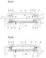
- FIGS 4a and 4b provide a better understanding of how the battery mounting device according to this embodiment, the plate 30 described in connection with Figure 3 being shown mounted in the device mounting.
- the plate 30 is mounted integral with an intermediate piece forming a spacer 42, preferably made by molding plastic material. Fixation of the plate 30 on the spacer 42 can be carried out by any known means of the skilled person.
- the spacer 42 has a plurality of studs 43 (only one being visible in FIG. 4), the section of which has a diameter substantially smaller than the diameter of the holes 38 of the wafer 30.
- the pins 43 of the spacer 42 are threaded in the holes 38 then are hot pressed to present a final structure of the rivet type, as shown in the figures.
- the assembly formed by the spacer 42 carrying the plate 30 is disposed at the interior of a battery housing 44 formed in a base 45 of an appliance portable electronics.
- the present illustration shows a cylindrical opening 46, provided in the base 45, to allow the insertion of the spacer and the plate from inside the portable electronic device.
- the opening 46 ends with an annular shoulder 47 forming the inner limit of the housing 44 and on which the spacer 42 is arranged to bear to be maintained in a fixed axial position relative to the housing 44.
- FIG. 4a shows that the tongues 32 of the wafer 30 are significantly apart in their rest position, that is to say they have a angle slightly greater than 90 degrees relative to the main part 31.
- the opening defined by the ends of the curved portions of the tongues 32 has a larger diameter than that of the stack 100.
- This characteristic allows advantageously to introduce the battery 100 into the housing 44 by depositing it simply on top of the spacer 42, by a movement comprising exclusively a straight translation of direction confused with the X axis of housing symmetry.
- the insertion of the battery at the bottom of the housing must include an additional step, compared to the preceding description, consisting of pressing on the pile to deform the tabs after having simply deposited on top of them.
- the spacer 42 further includes a bearing surface 48 for the stack 100 allowing to substantially define the axial position of the latter relative to the housing 44.
- the latter can be closed by a cover 49 having a shape similar to that of the cover 14 described in relationship with the first embodiment.
- the cover 49 indeed has a annular wall 50 which is arranged to fulfill a double function of fixing the cover 49 in housing 44 and holding tabs 32 against stack 100.
- the free end of the wall 50 has a short portion curved forming a notch 51 towards the periphery of the housing 44 and intended to cooperate with a bead 52 formed on the periphery of the housing 44.
- the internal surface of the wall 50 has two portions, from the cover 49 towards the curved end forming the notch 51, a first portion 53 being substantially parallel to the axis X of the housing 44, while the second portion 54 is slightly inclined with respect to the X axis in the direction of the periphery of the housing.
- the inclination of the second portion 54 of the wall 50 is preferably adjusted so that the internal diameter of the wall at the level of the notch 51 is substantially greater than the diameter of the opening defined by the tabs 32.
- the second portion 54 of the flange 50 comes into contact with the curved portion 36 of each of the tabs 32 to fulfill a function of guide surface.
- the cover 49 is lowered into housing 44, plus the tabs 32 undergo a elastic deformation towards the X axis of the housing.
- the wall 50 having also undergone an elastic deformation to allow the passage of the notch 51 under the bead 52, the tongues 32 are applied against the edge 102 of the stack 100, through their internal surfaces and their respective legs 41. A such a configuration is visible in FIG. 4b. The tabs are then held in this closed position due to the support formed by the first portion 53 of the wall 50.
- the wafer 30 is preferably obtained by stamping a sheet of metallic material, it is clear from Figure 4b that the tabs 32 allow to establish an electrical connection with a pole of the battery 100 (typically the positive pole, accessible on the face 103 and the section 102), in addition to ensuring the mechanical retention of the latter in the housing 44.
- a pole of the battery 100 typically the positive pole, accessible on the face 103 and the section 102
- the particular shape of the legs 41 guarantees good contact between the tongues 32 and the edge 102 of the stack 100, because they are preformed in the direction of the interior of the housing 44.
- Additional means are also provided for establish an electrical connection of the wafer 30 with the electronic circuits of portable electronic device.
- connection means with the second pole of the battery 100, accessible via the face 101 of the stack, oriented towards the bottom of the housing 44, have been shown by way of nonlimiting example.
- These connection means include for example a spring 55 of the coil spring type made of electrically material conductor and, connected by a first end (not shown) to the circuits electronics of the portable electronic device.
- the second end of spring 55 is brought into contact with the face 101 of the stack 100, the spring extending through the hole 39 in plate 30 (shown in Figure 3) and through a similar hole (not shown) formed in the spacer 42, opposite the hole 39.
- the structure of the present embodiment ensures a retention quality of the battery 100 in the housing 44 comparable to that of the first embodiment.
- maintaining the battery 100 and maintaining the cover 49 in housing 44 in the event of a violent shock are guaranteed with the same effectiveness as in the case of the structure previously described in relation to FIGS. 1 and 2.
- an O-ring 56 is arranged around of the wall 50 to seal the housing 44 when the cover 49 is put in place, by compression between the cover 49 and the bead 52.
- a wall of the same type that the wall 50 must be arranged on the face of the bottom intended to be placed opposite the battery compartment.
- the structure of the present mounting device of battery in an electronic device makes it easy to consider automation mounting the battery as part of the assembly of the electronic device.
- the placement of the stack is even more simple since the aforementioned pressure is not even necessary to make lower the battery into the housing.
- the operation of depositing the battery in the housing can be achieved by simple straight translation from the environment exterior to interior of the accommodation. This particular property presents a definite economic advantage, especially in the production of devices electronic manufactured in large number of copies.
Landscapes
- Chemical & Material Sciences (AREA)
- Chemical Kinetics & Catalysis (AREA)
- Electrochemistry (AREA)
- General Chemical & Material Sciences (AREA)
- Engineering & Computer Science (AREA)
- Power Engineering (AREA)
- Physics & Mathematics (AREA)
- General Physics & Mathematics (AREA)
- Battery Mounting, Suspending (AREA)
Priority Applications (1)
| Application Number | Priority Date | Filing Date | Title |
|---|---|---|---|
| EP02028484.0A EP1432052B1 (de) | 2002-12-19 | 2002-12-19 | Vorrichtung zur Montage von einer Energiequelle für tragbares elektronisches Gerät |
Applications Claiming Priority (1)
| Application Number | Priority Date | Filing Date | Title |
|---|---|---|---|
| EP02028484.0A EP1432052B1 (de) | 2002-12-19 | 2002-12-19 | Vorrichtung zur Montage von einer Energiequelle für tragbares elektronisches Gerät |
Publications (2)
| Publication Number | Publication Date |
|---|---|
| EP1432052A1 true EP1432052A1 (de) | 2004-06-23 |
| EP1432052B1 EP1432052B1 (de) | 2017-03-01 |
Family
ID=32338048
Family Applications (1)
| Application Number | Title | Priority Date | Filing Date |
|---|---|---|---|
| EP02028484.0A Expired - Lifetime EP1432052B1 (de) | 2002-12-19 | 2002-12-19 | Vorrichtung zur Montage von einer Energiequelle für tragbares elektronisches Gerät |
Country Status (1)
| Country | Link |
|---|---|
| EP (1) | EP1432052B1 (de) |
Cited By (3)
| Publication number | Priority date | Publication date | Assignee | Title |
|---|---|---|---|---|
| EP3054359A1 (de) | 2015-02-05 | 2016-08-10 | ETA SA Manufacture Horlogère Suisse | Montagevorrichtung einer elektrischen Energiequelle |
| CN109270830A (zh) * | 2018-11-22 | 2019-01-25 | 歌尔科技有限公司 | 屏幕安装结构及腕戴电子产品 |
| CN109519042A (zh) * | 2017-09-20 | 2019-03-26 | 株式会社东海理化电机制作所 | 密封结构 |
Citations (2)
| Publication number | Priority date | Publication date | Assignee | Title |
|---|---|---|---|---|
| US3945193A (en) * | 1973-01-26 | 1976-03-23 | Citizen Watch Co., Ltd. | Battery holder |
| WO2001077760A1 (en) * | 2000-04-06 | 2001-10-18 | Seiko Instruments Inc. | Structure for holding battery of electronic timepiece |
-
2002
- 2002-12-19 EP EP02028484.0A patent/EP1432052B1/de not_active Expired - Lifetime
Patent Citations (2)
| Publication number | Priority date | Publication date | Assignee | Title |
|---|---|---|---|---|
| US3945193A (en) * | 1973-01-26 | 1976-03-23 | Citizen Watch Co., Ltd. | Battery holder |
| WO2001077760A1 (en) * | 2000-04-06 | 2001-10-18 | Seiko Instruments Inc. | Structure for holding battery of electronic timepiece |
Non-Patent Citations (1)
| Title |
|---|
| DATABASE WPI Section EI Week 200176, Derwent World Patents Index; Class S04, AN 2001-663073, XP002242261 * |
Cited By (5)
| Publication number | Priority date | Publication date | Assignee | Title |
|---|---|---|---|---|
| EP3054359A1 (de) | 2015-02-05 | 2016-08-10 | ETA SA Manufacture Horlogère Suisse | Montagevorrichtung einer elektrischen Energiequelle |
| CN109519042A (zh) * | 2017-09-20 | 2019-03-26 | 株式会社东海理化电机制作所 | 密封结构 |
| EP3460869A1 (de) * | 2017-09-20 | 2019-03-27 | Kabushiki Kaisha Tokai Rika Denki Seisakusho | Dichtungsstruktur |
| CN109519042B (zh) * | 2017-09-20 | 2021-06-29 | 株式会社东海理化电机制作所 | 密封结构 |
| CN109270830A (zh) * | 2018-11-22 | 2019-01-25 | 歌尔科技有限公司 | 屏幕安装结构及腕戴电子产品 |
Also Published As
| Publication number | Publication date |
|---|---|
| EP1432052B1 (de) | 2017-03-01 |
Similar Documents
| Publication | Publication Date | Title |
|---|---|---|
| EP1416582B1 (de) | Tragbare elektronische Vorrichtung mit einer elektrischen Verbindung in dem Vorrichtungsgehäuse | |
| WO1994026582A1 (fr) | Dispositif de fixation d'une chaussure sur une pedale, et chaussure et pedale equipees d'un tel dispositif | |
| EP0024364B1 (de) | Vorrichtung zum Halten einer Batterie in einer elektronischen Armbanduhr | |
| FR2836714A1 (fr) | Projecteur comprenant une lentille en verre et un support de lentille en matiere plastique et outil de surmoulage du support sur la lentille | |
| EP1513221A1 (de) | Tragbares Armbandgerät mit elektrischem Verbindungselement durchs Gehäuse und Verfahren zur Montage des Verbindungselements | |
| EP0209717B1 (de) | Batteriekammer für elektronische Uhr | |
| EP3179533B1 (de) | Tragbares elektronisches gerät, das mit einem batteriefach ausgestattet ist | |
| EP3254159B1 (de) | Montagevorrichtung einer elektrischen energiequelle | |
| EP2259366B1 (de) | Elektrische Vorrichtung mit automatischer Einschaltung durch Hebung | |
| EP1432052B1 (de) | Vorrichtung zur Montage von einer Energiequelle für tragbares elektronisches Gerät | |
| CH680245A5 (de) | ||
| EP0785107A1 (de) | Lenkrad und zugehöriges Sicherheitsmodul | |
| EP2745661A2 (de) | Elektrische verbindungsvorrichtung, anordnung mit einer solchen vorrichtung und elektronikplatine sowie verfahren zum elektrischen anschluss einer elektronikplatine | |
| EP1139060B1 (de) | Pyrotechnischer Zünder mit einem elektrischen oder elektronischen Bauelement und/oder mit einem Steckverbinder | |
| EP0004503B1 (de) | Taschenlampengehäuse | |
| EP0395505A1 (de) | Vorrichtung zur Befestigung von Gegenständen auf einer beliebigen Unterlage und Gegenstand, insbesondere Gehäuse, versehen mit mindestens einer derartigen Befestigungsvorrichtung | |
| EP1729359B1 (de) | Halte- und Anschlussvorrichtung für eine Batterie | |
| FR2824622A3 (fr) | Anneau de liaison pour projecteur de vehicules | |
| WO2011042283A1 (fr) | Connecteur traversant pour support métallique, pièce isolante et support métallique associés | |
| CH710698A2 (fr) | Dispositif de montage d'une source d'énergie électrique. | |
| CH683582B5 (fr) | Pièce d'horlogerie comportant un élément fixé rigidement sur une pièce de base en matière plastique. | |
| FR2954011A1 (fr) | Accessoire de montage d'un ou plusieurs cables electriques ou similaires sur un element comprenant au moins une gorge retentive | |
| EP0236649A1 (de) | Elektrische Lampe, insbesondere Taschenlampe | |
| EP3010099A1 (de) | Leistungsschalterplatte | |
| FR2709601A1 (fr) | Cosse pour batterie. |
Legal Events
| Date | Code | Title | Description |
|---|---|---|---|
| PUAI | Public reference made under article 153(3) epc to a published international application that has entered the european phase |
Free format text: ORIGINAL CODE: 0009012 |
|
| AK | Designated contracting states |
Kind code of ref document: A1 Designated state(s): AT BE BG CH CY CZ DE DK EE ES FI FR GB GR IE IT LI LU MC NL PT SE SI SK TR |
|
| AX | Request for extension of the european patent |
Extension state: AL LT LV MK RO |
|
| 17P | Request for examination filed |
Effective date: 20041223 |
|
| AKX | Designation fees paid |
Designated state(s): CH DE LI |
|
| 17Q | First examination report despatched |
Effective date: 20160622 |
|
| GRAP | Despatch of communication of intention to grant a patent |
Free format text: ORIGINAL CODE: EPIDOSNIGR1 |
|
| INTG | Intention to grant announced |
Effective date: 20161124 |
|
| RIN1 | Information on inventor provided before grant (corrected) |
Inventor name: HENRIET, FABIEN Inventor name: REBEAUD, JEAN-PHILIPPE Inventor name: KAELIN, LAURENT |
|
| GRAS | Grant fee paid |
Free format text: ORIGINAL CODE: EPIDOSNIGR3 |
|
| GRAA | (expected) grant |
Free format text: ORIGINAL CODE: 0009210 |
|
| AK | Designated contracting states |
Kind code of ref document: B1 Designated state(s): CH DE LI |
|
| REG | Reference to a national code |
Ref country code: CH Ref legal event code: EP Ref country code: CH Ref legal event code: NV Representative=s name: ICB INGENIEURS CONSEILS EN BREVETS SA, CH |
|
| REG | Reference to a national code |
Ref country code: DE Ref legal event code: R096 Ref document number: 60248691 Country of ref document: DE |
|
| REG | Reference to a national code |
Ref country code: DE Ref legal event code: R097 Ref document number: 60248691 Country of ref document: DE |
|
| PLBE | No opposition filed within time limit |
Free format text: ORIGINAL CODE: 0009261 |
|
| STAA | Information on the status of an ep patent application or granted ep patent |
Free format text: STATUS: NO OPPOSITION FILED WITHIN TIME LIMIT |
|
| 26N | No opposition filed |
Effective date: 20171204 |
|
| PGFP | Annual fee paid to national office [announced via postgrant information from national office to epo] |
Ref country code: DE Payment date: 20191119 Year of fee payment: 18 |
|
| REG | Reference to a national code |
Ref country code: DE Ref legal event code: R079 Ref document number: 60248691 Country of ref document: DE Free format text: PREVIOUS MAIN CLASS: H01M0002100000 Ipc: H01M0050200000 |
|
| REG | Reference to a national code |
Ref country code: DE Ref legal event code: R119 Ref document number: 60248691 Country of ref document: DE |
|
| PG25 | Lapsed in a contracting state [announced via postgrant information from national office to epo] |
Ref country code: DE Free format text: LAPSE BECAUSE OF NON-PAYMENT OF DUE FEES Effective date: 20210701 |
|
| PGFP | Annual fee paid to national office [announced via postgrant information from national office to epo] |
Ref country code: CH Payment date: 20211119 Year of fee payment: 20 |
|
| REG | Reference to a national code |
Ref country code: CH Ref legal event code: PL |