EP1431983A1 - Method and device for manufacturing wire harness - Google Patents
Method and device for manufacturing wire harness Download PDFInfo
- Publication number
- EP1431983A1 EP1431983A1 EP02762853A EP02762853A EP1431983A1 EP 1431983 A1 EP1431983 A1 EP 1431983A1 EP 02762853 A EP02762853 A EP 02762853A EP 02762853 A EP02762853 A EP 02762853A EP 1431983 A1 EP1431983 A1 EP 1431983A1
- Authority
- EP
- European Patent Office
- Prior art keywords
- electric wire
- wire
- wiring harness
- units
- electric
- Prior art date
- Legal status (The legal status is an assumption and is not a legal conclusion. Google has not performed a legal analysis and makes no representation as to the accuracy of the status listed.)
- Withdrawn
Links
Images


Classifications
-
- H—ELECTRICITY
- H01—ELECTRIC ELEMENTS
- H01B—CABLES; CONDUCTORS; INSULATORS; SELECTION OF MATERIALS FOR THEIR CONDUCTIVE, INSULATING OR DIELECTRIC PROPERTIES
- H01B13/00—Apparatus or processes specially adapted for manufacturing conductors or cables
- H01B13/012—Apparatus or processes specially adapted for manufacturing conductors or cables for manufacturing wire harnesses
- H01B13/01209—Details
-
- H—ELECTRICITY
- H01—ELECTRIC ELEMENTS
- H01B—CABLES; CONDUCTORS; INSULATORS; SELECTION OF MATERIALS FOR THEIR CONDUCTIVE, INSULATING OR DIELECTRIC PROPERTIES
- H01B13/00—Apparatus or processes specially adapted for manufacturing conductors or cables
- H01B13/34—Apparatus or processes specially adapted for manufacturing conductors or cables for marking conductors or cables
- H01B13/345—Apparatus or processes specially adapted for manufacturing conductors or cables for marking conductors or cables by spraying, ejecting or dispensing marking fluid
-
- Y—GENERAL TAGGING OF NEW TECHNOLOGICAL DEVELOPMENTS; GENERAL TAGGING OF CROSS-SECTIONAL TECHNOLOGIES SPANNING OVER SEVERAL SECTIONS OF THE IPC; TECHNICAL SUBJECTS COVERED BY FORMER USPC CROSS-REFERENCE ART COLLECTIONS [XRACs] AND DIGESTS
- Y10—TECHNICAL SUBJECTS COVERED BY FORMER USPC
- Y10T—TECHNICAL SUBJECTS COVERED BY FORMER US CLASSIFICATION
- Y10T29/00—Metal working
- Y10T29/49—Method of mechanical manufacture
- Y10T29/49002—Electrical device making
- Y10T29/49117—Conductor or circuit manufacturing
- Y10T29/49169—Assembling electrical component directly to terminal or elongated conductor
-
- Y—GENERAL TAGGING OF NEW TECHNOLOGICAL DEVELOPMENTS; GENERAL TAGGING OF CROSS-SECTIONAL TECHNOLOGIES SPANNING OVER SEVERAL SECTIONS OF THE IPC; TECHNICAL SUBJECTS COVERED BY FORMER USPC CROSS-REFERENCE ART COLLECTIONS [XRACs] AND DIGESTS
- Y10—TECHNICAL SUBJECTS COVERED BY FORMER USPC
- Y10T—TECHNICAL SUBJECTS COVERED BY FORMER US CLASSIFICATION
- Y10T29/00—Metal working
- Y10T29/49—Method of mechanical manufacture
- Y10T29/49002—Electrical device making
- Y10T29/49117—Conductor or circuit manufacturing
- Y10T29/49174—Assembling terminal to elongated conductor
- Y10T29/49181—Assembling terminal to elongated conductor by deforming
- Y10T29/49185—Assembling terminal to elongated conductor by deforming of terminal
-
- Y—GENERAL TAGGING OF NEW TECHNOLOGICAL DEVELOPMENTS; GENERAL TAGGING OF CROSS-SECTIONAL TECHNOLOGIES SPANNING OVER SEVERAL SECTIONS OF THE IPC; TECHNICAL SUBJECTS COVERED BY FORMER USPC CROSS-REFERENCE ART COLLECTIONS [XRACs] AND DIGESTS
- Y10—TECHNICAL SUBJECTS COVERED BY FORMER USPC
- Y10T—TECHNICAL SUBJECTS COVERED BY FORMER US CLASSIFICATION
- Y10T29/00—Metal working
- Y10T29/51—Plural diverse manufacturing apparatus including means for metal shaping or assembling
- Y10T29/5136—Separate tool stations for selective or successive operation on work
- Y10T29/5137—Separate tool stations for selective or successive operation on work including assembling or disassembling station
- Y10T29/5138—Separate tool stations for selective or successive operation on work including assembling or disassembling station and means to machine work part to fit cooperating work part
-
- Y—GENERAL TAGGING OF NEW TECHNOLOGICAL DEVELOPMENTS; GENERAL TAGGING OF CROSS-SECTIONAL TECHNOLOGIES SPANNING OVER SEVERAL SECTIONS OF THE IPC; TECHNICAL SUBJECTS COVERED BY FORMER USPC CROSS-REFERENCE ART COLLECTIONS [XRACs] AND DIGESTS
- Y10—TECHNICAL SUBJECTS COVERED BY FORMER USPC
- Y10T—TECHNICAL SUBJECTS COVERED BY FORMER US CLASSIFICATION
- Y10T29/00—Metal working
- Y10T29/51—Plural diverse manufacturing apparatus including means for metal shaping or assembling
- Y10T29/5193—Electrical connector or terminal
Definitions
- the present invention relates to a wiring harness manufacturing method and a wiring harness manufacturing apparatus for manufacturing a wiring harness arranged on a motor vehicle.
- the wiring harness is arranged on the motor vehicle so that electric power from a power source and control signals from a computer can be supplied to the electronic equipment.
- the wiring harness has electric wires and connectors attached to end portions of the electric wires.
- the electric wire has a conductive core wire and an insulative covering portion covering the conductive core wire.
- the electric wire is a so-called covered or sheathed wire.
- the connector has a conductive terminal fitting and an insulative connector housing.
- the terminal fitting is attached to an end portion of the electric wire and is electrically-connected with the core wire of the electric wire.
- the connector housing is formed in a box-shape and accommodates the terminal fittings.
- the electric wire is firstly cut in a fixed length, and the terminal fitting is attached to the end portion of the electric wire.
- the electric wires are connected as the need arises.
- the terminal fitting is inserted into the connector housing.
- the above-described wiring harness is manufactured or assembled.
- the thickness of the core wire, material (for example, from view point of heat-resistance) of the covering portion, and service conditions should be distinguished.
- the service conditions mean systems such as an air-bag system, an antilock brake system, and a power transmission system in which the electric wires are used.
- the electric wires of the wiring harness are variously colored and marked for distinguishing the above systems.
- the above coloring and marking are carried out in a process of manufacturing the electric wire by forming the core wire from conductive metal such as copper.
- the wiring harness sometimes consists of not less than 100 kinds of the electric wires. Therefore, a factory to manufacture or assemble the wiring harness has to stock not less than 100 kinds of electric wires, while making the stock control of the electric wires having each article number. And therefore, the cost for stocking the electric wires tends to increase.
- the electric wire with a determined article number needs to be set in a device to cut off the electric wire in a fixed length.
- a mistake in the article number of the electric wire would arise. Therefore, the yield of the wiring harness is reduced, thereby causing reduction of the productive efficiency of the wiring harness.
- the applicant of the present invention has suggested a wiring harness manufacturing method described in Japanese Patent Application Laid-open No.61-245412.
- this wiring harness manufacturing method the electric wires are colored and marked just before each of the wire manufacturing step, the cutting step, the cover removing step, the terminal-crimping step, and the case insertion step.
- a device for coloring and marking the electric wire has to be provided on each of a wire cutting unit, a covering portion removing unit, a terminal crimping unit, and a terminal inserting unit.
- the prior art wiring harness manufacturing method also requires installation or mounting work of the above coloring and marking device between each two units, and requires the wiring harness to be set on each coloring and marking device.
- an object of the present invention is to provide a wiring harness manufacturing method and a wiring harness manufacturing apparatus, wherein the above drawbacks of the prior art wiring harness manufacturing method and apparatus have been solved and therefore manufacturing costs of the wiring harness can be reduced.
- a wiring harness manufacturing method for assembling a wiring harness having electric wires and connectors attached to the electric wires comprises the steps of: a wire stocking step to stock the electric wires; and a cutting step to cut an electric wire stocked in the wire stocking step in a desirable length and to attach a terminal fitting of the connector to the electric wire, wherein, an outer surface of the electric wire is colored in at least one of the wire stocking step and the cutting step.
- the electric wire is colored in at least one of the wire stocking step and the cutting step.
- the device to color the electric wire needs not to be attached to all the units to carry out the wire stocking step and the cutting step.
- the electric wire is not necessarily colored in all the steps, all the electric wires need not to be conveyed to the devices to color the electric wire from the units to carry out the wire stocking step and the cutting step. Further, the electric wire is colored in a step for assembling the wiring harness. Therefore, the article number (the kind of color of the outer surface) of the electric wire stocked by the wire stocking units can be reduced.
- to color the outer surface of the electric wire means to color the outer surface of the covering portion of the electric wire with a colorant.
- the colorant is a liquid substance in which color material (organic substance for industry) is dissolved and dispersed in water or in other solvent.
- color material organic substance for industry
- dyes and pigments mostly organic substance and synthetic material.
- colorant means both paint and coloring liquid.
- the dye In the coloring liquid, the dye is dissolved or dispersed in the solvent. In the paint, the pigment is dispersed in the dispersion liquid. Therefore, when the outer surface of the covering portion is colored by the coloring liquid, the dye soaks into in the covering portion, and when the outer surface of the covering portion is colored by the paint, the pigment adheres to the outer surface without soaking into the covering portion. That is, "to color the outer surface of the covering portion of the electric wire" in the present specification means to dye the outer surface of the covering portion of the electric wire 'with the dye and also to paint the pigment on the outer surface of the covering portion of the electric wire.
- the solvent and the dispersion liquid should have an affinity for synthetic resin forming the covering portion of the electric wire so that the dye securely soaks into the covering portion of the electric wire and the pigment securely adheres to the outer surface of the covering portion of the electric wire.
- a wiring harness manufacturing method for assembling a wiring harness having electric wires and connectors attached to the electric wires comprises the steps of: a wire stocking step to stock the electric wires; and a cutting step to cut an electric wire stocked in the wire stocking step in a desirable length and to attach a terminal fitting of the connector to the electric wire, a joining step to connect the electric wires which have been cut in desirable lengthes by the cutting step and to which the respective terminal fittings have been attached, wherein, an outer surface of the electric wire is colored in both the wire stocking step and one of the cutting step and the joining step.
- the electric wire is colored in at least one of the wire cutting step and the joining step.
- the device to color the electric wire needs not to be attached to all the units to carry out the wire cutting step and the joining step.
- the electric wire is not necessarily colored in all the steps, all the electric wires need not to be conveyed to the devices to color the electric wire from the units to carry out the wire stocking step, the cutting step, and the joining step. Further, the electric wire is colored in a step for assembling the wiring harness. Therefore, the article number (the kind of color of the outer surface) of the electric wire stocked by the wire stocking units can be reduced.
- the coloring means to color the electric wire are attached to one of the wire stocking units and the cutting units.
- the coloring means need not to be provided on all the wire stocking units and the cutting units.
- the electric wire is colored by the coloring means in a step for assembling the wiring harness. Therefore, the article number (the kind of color of the outer surface) of the electric wire stocked by the wire stocking units can be reduced.
- a wiring harness manufacturing apparatus for assembling a wiring harness having electric wires and connectors attached to the electric wires comprises: wire stocking units each to stock the electric wires; and cutting units each to cut the electric wires stocked in the wire stocking units in desirable lengthes and to attach terminal fittings of the connectors to the respective electric wires; and joining units to connect the electric wires which have been cut in desirable lengthes by the cutting units and to which the respective terminal fittings have been attached, wherein, a coloring means to color an outer surface of each of the electric wires is attached to one of the wire stocking units, the cutting units, and the joining units.
- the coloring means to color the electric wire are attached to one of the wire stocking units, the cutting units, and the joining units.
- the coloring means need not to be provided on all the wire stocking units, the cutting units, and the joining units.
- the electric wire is colored by the coloring means in a step for assembling the wiring harness. Therefore, the article number (the kind of color of the outer surface) of the electric wire stocked by the wire stocking units can be reduced.
- the wiring harness 2 is arranged on a motor vehicle.
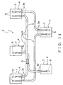
- the wiring harness 2 has electric wires 3, connectors 4, and joint-terminals 5 as shown in FIG.14.
- the electric wire 3 is a covered wire having a conductive core wire and an insulative covering portion covering the core wire.
- the electric wires 3 are bundled.
- the connector 4 has a conductive terminal fitting 6 and an insulative connector housing 7.
- the terminal fitting 6 is formed by bending a conductive sheet metal.
- the terminal fitting 6 is attached to an end portion 3a of the electric wire 3.
- the terminal fitting 6 is electrically-connected with the core wire of the electric wire 3.
- the connector housing 7 is formed in a box-shape.
- the connector housing 7 accommodates the terminal fitting 6. Like this, the terminal fitting 6 is attached to the connector housing 7.
- the joint-terminal 5 is made of conductive sheet metal.
- the joint-terminal 5 electrically-connects core wires of the respective electric wires 3.
- the covering portions of the electric wires 3 are removed, and the core wires are exposed.
- the joint-terminal 5 covers the exposed core wires.
- the joint-terminal 5 crimps the core wires of the electric wires 3, thereby electrically-connecting the electric wires 3.
- the electric wires 3 have been cut off in desirable lengthes, and the covering portions of the end portions 3a have been removed.
- the terminal fittings 6 are crimped to the core wires exposed from the end portions 3a.
- the covering portions of the connecting portion of the electric wires 3a are removed.
- the core wires exposed from the connecting portion are crimped by the joint-terminal 5 so as to connect the electric wires 3.
- the terminal fitting 6 is inserted into, and attached to, the connector housing 7.
- the wiring harness 2 of the above structure is assembled.
- the wiring harness 2 connects a plurality of electronic equipment mounted on a motor vehicle by coupling the above connectors 4 with mating connectors of the electronic equipment.
- the wiring harness 2 supplies electric power or transmits control signals to the electronic equipment.
- the wiring harness manufacturing apparatus 1 assembles or manufactures the wiring harness 2 of the above structure.
- the wiring harness manufacturing apparatus 1 has wire stocking units 10, cutting units 11, joining units 12 and case insertion unit 13 as shown in FIG.1.
- the wiring harness manufacturing apparatus 1 has a pair of wire stocking units 10, a pair of cutting units 11 and a pair of joining units 12.
- the electric wire 3 is supplied to the wire stocking unit 10 from a wire manufacturing apparatus 9.
- the electric wire 3 is, for example, rolled on a real.
- the wire manufacturing apparatus 9 makes the above core wire from conductive metal such as copper.
- the core wire is covered with insulative synthetic resin by the wire manufacturing apparatus 9.
- the covering portion of the electric wire 3 made by the wire manufacturing apparatus 9 is in a non-colored state. That is, a non-colored electric wire 3 is supplied to the wire stocking unit 10.
- the non-colored electric wire 3 has the covering portion of synthetic resin in which colorant is not put. That is, the covering portion of the non-colored electric wire 3 has a color of synthetic resin itself.
- to color the outer surface of the electric wire 3 means to color the outer surface of the covering portion of the electric wire 3 with a colorant.
- the colorant is a liquid substance in which color material (organic substance for industry) is dissolved and dispersed in water or in other solvent.
- color material organic substance for industry
- dyes and pigments mostly organic substance and synthetic material.
- colorant means both paint and coloring liquid.
- the dye In the coloring liquid, the dye is dissolved or dispersed in the solvent. In the paint, the pigment is dispersed in the dispersion liquid. Therefore, when the outer surface of the covering portion is colored by the coloring liquid, the dye soaks into in the covering portion, and when the outer surface of the covering portion is colored by the paint, the pigment adheres to the outer surface without soaking into the covering portion. That is, "to color the outer surface of the covering portion of the electric wire" in the present specification means to dye the outer surface of the covering portion of the electric wire 3 with the dye and also to paint the pigment on the outer surface of the covering portion of the electric wire 3.
- the solvent and the dispersion liquid should have an affinity for synthetic resin forming the covering portion of the electric wire 3 so that the dye securely soaks into the covering portion of the electric wire 3 and the pigment securely adheres to the outer surface of the covering portion of the electric wire 3.
- the wire stocking unit 10 once stocks the electric wire 3 supplied from the wire manufacturing apparatus 9.
- the painting devices 14,15,16 as the coloring means are attached to one of the pair of wire stocking units 10 (hereinafter, 10a).
- the painting devices 14,15,16 color the outer surface of the above electric wire 3 differently from a color of synthetic resin of the covering portion.
- Each of the pair of wire stocking units 10a,10b supplies the electric wires 3 to the respective cutting units 11.
- the electric wire 3 supplied to the cutting unit 11 is in a state of being rolled on a reel.
- the cutting unit 11 cuts off the electric wire 3 in a desirable length.
- the cutting unit 11 removes the covering portions of the end portions 3a of the electric wire 3.
- the cutting unit 11 attaches the terminal fittings 6 to the respective end portions 3a of the electric wire 3.
- At least one of the painting devices 17,18,19 is attached to one cutting unit (hereinafter, 11 a) of the pair of cutting units 11.
- the painting devices 17,18,19 are attached to the cutting unit 11a.
- the painting devices 17,18,19 color the outer surface of the above electric wire 3 differently from a color of synthetic resin of the covering portion.
- At least one of the painting devices 18,19 as the coloring means is attached to one joining unit (hereinafter, 12a) of the pair of joining units 12.
- the painting devices 18,19 are attached to the joining unit 12a.
- the painting devices 18,19 color the outer surface of the above electric wire 3 differently from a color of synthetic resin of the covering portion.
- the electric wire 3, to which the terminal fittings 6 have been attached by the other cutting unit 11b, is supplied to the joining unit 12a from the cutting unit 11b.
- the electric wire 3, to which the terminal fittings 6 have been attached, is supplied to the other joining unit 12b from each of the pair of cutting units 11a, 11b.
- the joining units 12a, 12b remove the covering portions of the above-described connecting portions of the electric wires 3 and crimp the core wires with the joint-terminal 5 so as to connect the electric wires 3.
- the electric wire 3 with the terminal fitting 6 is supplied to the case insertion unit 13 from each of the pair of joining units 12a,12b.
- the case insertion unit 13 inserts the terminal fitting 6 attached to the end portion 3 a of the electric wire 3 into the connector housing 7, thereby assembling the connector 4.
- the painting- device 14 has an apparatus body 14a, a pair of rollers 14b, a plurality of sprayers 14c and a dryer 14d as shown in FIG.3(a).
- the pair of rollers 14b are arranged with some interval, and the electric wire 3 is arranged between the rollers 14b.
- a pair of sprayers 14c are provided in the illustrated embodiment.
- the sprayer 14c sprays the colorant toward the electric wire 3 traveling between the rollers 14b.
- the pair of sprayers 14c color the outer surface of the electric wire 3 over the whole periphery thereof.
- the sprayers 14c color the outer surface of the electric wire 3 differently from a color of synthetic resin of the covering portion over the whole periphery of the electric wire 3.
- the drier 14d is arranged downstream of the sprayers 14c in a traveling direction of the electric wire 3.
- the drier 14d dries the colorant blown on the outer surface of the electric wire 3 by the sprayers 14c.
- the painting device 14 of the above structure colors the outer surface of the electric wire 3 in a color P (a hatched portion in FIG.3(b)) different from a color of synthetic resin of the covering portion over the whole periphery of the electric wire 3.
- the painting device 15 has a pair of rollers 15a, sprayers 15b and markers 15c as shown in FIG.4(a).
- the pair of rollers 15a are arranged with some interval, and the electric wire 3 is arranged between the rollers 15a.
- a pair of sprayers 15b are provided in the illustrated embodiment.
- the sprayer 15b sprays the colorant toward the electric wire 3 traveling between the rollers 15a.
- the sprayers 15b color the outer surface of the electric wire 3.
- the sprayers 15b color the outer surface of the electric wire 3 differently from a color of synthetic resin of the covering portion over the whole periphery of the electric wire 3.
- a pair of markers 15c are provided in the illustrated embodiment.
- the markers 15c are arranged downstream of the sprayers 15b in a traveling direction of the electric wire 3.
- the marker 15c puts the colorant partly on the outer surface of the electric wire 3, which colorant has a color different from both the color colored by the sprayer 15b and the color of the covering portion.
- the sprayer 15b colors the outer surface of the electric wire 3 in a color P (a hatched portion in FIG.4(b)) different from a color of synthetic resin of the covering portion over the whole periphery of the electric wire 3.
- the marker 15c colors the outer surface, having been colored by the sprayer 15b, in a color R different from the color P and the color of the covering portion itself.
- the painting device 15 colors the outer surface of the electric wire 3 in a pattern of stripe of the colors P,R as shown in FIG.4(b).
- the painting device 16 has a pair of rollers 16a and a plurality of markers 16b as shown in FIG.5(a).
- the pair of rollers 16a are arranged with some interval, and the electric wire 3 is arranged between the rollers 16a.
- a pair of markers 16b are provided in the illustrated embodiment.
- the marker 16b partly put a colorant on the outer surface of the electric wire 3.
- the pair of markers 16b partly color the outer surface of the electric wire 3 differently from a color of synthetic resin of the covering portion.
- the marker 16b partly colors the outer surface of the electric wire 3 in a color R (a hatched portion in FIG.5(b)) different from a color of synthetic resin of the covering portion.
- the painting device 16 colors the outer surface of the electric wire 3 in a pattern of stripe of the color R as shown in FIG.5(b).
- the painting device 17 has a pair of running rollers 17a, a tubular member 17b and a coloring unit 17c as shown in FIG.6(a).
- the pair of running rollers 17a put the electric wire 3 therebetween and make the electric wire 3 run.
- the tubular member 17b is formed tubularly in order to receive the end portion 3a of the electric wire 3.
- the tubular member 17b is provided with a through-hole 17d.
- the coloring unit 17c partly puts a colorant on the outer surface of the electric wire 3 in the tubular member 17b through the through-hole 17d.
- the coloring unit 17c partly colors the outer surface of the electric wire 3 differently from a color of synthetic resin of the covering portion (that is, marking is carried out on the end portion).
- the coloring unit 17c partly colors the outer surface of the electric wire 3 in a color S (a hatched portion in FIG.6(b)) different from the colors P,R.
- the painting device 17 partly colors the outer surface of the electric wire 3 in the color S so as to form a mark 20 as shown in FIG.6(b).
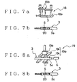
- the painting device 18 has wire clampers 18a and sprayers 18b as shown in FIG.7(a).
- the wire clamper 18a clamps the end portion 3a of the electric wire 3.
- the sprayer 18b partly sprays a colorant on the outer surface of the end portion 3a of the electric wire 3.
- the sprayer 18b partly colors the outer surface of the electric wire 3 differently from a color of synthetic resin of the covering portion (that is, marking is carried out on the end portion).
- the sprayer 18b partly colors the outer surface of the electric wire 3 in a color S (a hatched portion in FIG.7(b)) different from the colors P,R.
- the painting device 18 partly colors the outer surface of the electric wire 3 in the color S so as to form a mark 20 as shown in FIG.7(b).
- the painting device 19 has wire clampers 19a and a stamper 19b as shown in FIG.8(a).
- the wire clamper 19a has holding members 19c,19c which close and open each other.
- the wire clamper 19a sandwiches the end portion 3a of the electric wire 3 between the holding members 19c,19c.
- the stamper 19b moves relative to the end portion 3a of the electric wire 3 along with the holding members 19c,19c. That is, the stamper 19b approaches the end portion 3a of the electric wire 3 when the holding members 19c,19c close each other.
- the stamper 19b is put into contact with the end portion 3a and partly puts a colorant on the outer surface of the end portion 3a.
- the stamper 19b partly colors the outer surface of the electric wire 3 differently from a color of synthetic resin of the covering portion (that is, marking is carried out on the end portion).
- the stamper 19b partly colors the outer surface of the electric wire 3 in a color S (a hatched portion in FIG.8(b)) different from the colors P,R
- the painting device 19 partly colors the outer surface of the electric wire 3 in the color S so as to form a mark 20 as shown in FIG.8(b).
- the electric wire 3 wound up on a reel is firstly stocked once in each of the wire stocking units 10a, 10b at Step S1 as a wire stocking step in FIG.2 and FIG.9.
- the wire stocking unit 10a colors the outer surface of the electric wire 3 over the whole periphery thereof by using the painting device 14, forms (colors) a stripe pattern on the outer surface of the electric wire 3 by using the painting device 15, or forms (colors) a stripe pattern on the outer surface of the electric wire 3 by using the painting device 16. And then, Step S2 (shown in FIG.2 and FIG.9) as a cutting step is reached.
- Step S2 the electric wires 3 are conveyed toward the cutting units 11a, 11b from the wire stocking units 10a,10b.
- the cutting units 11a, 11b cut off the electric wires 3 in desirable lengthes, remove the covering portions of the end portions 3a, and attach the terminal fittings 6 to the end portions 3a.
- the cutting unit 11a forms the mark 20 on the end portion 3a of the electric wire 3 by using one of the painting devices 17,18,19 (that is, marking is carried out on the end portion). And then, Step S3 (shown in FIG.2 and FIG.9) as a joining step is reached.
- Step S3 the electric wire 3 is conveyed toward the joining unit 12b from the cutting unit 11a, and the electric wires 3 are conveyed toward the joining units 12a, 12b from the cutting unit 11b.
- the joining units 12a,12b remove the covering portions of the connecting portions of the electric wires 3 and connect the electric wires 3 with the joint-terminal 5.
- the joining unit 12a forms the mark 20 on the end portion 3a of the electric wire 3 by using one of the painting devices 18,19 (that is, marking is carried out on the end portion). And then, Step S4 (shown in FIG.2 and FIG.9) as a case insertion step is reached.
- Step S4 the electric wires 3 are conveyed toward the case insertion unit 13 from the joining units 12a,12b.
- the case insertion unit 13 inserts the terminal fitting 6 attached to the end portion 3a of the electric wire 3 into the connector housing 7.
- the wiring harness manufacturing apparatus 1 assembles the wiring harness 2.
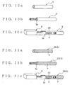
- the non-colored electric wire 3 shown in FIG.10(a) is supplied to the wire stocking unit 10b, the covering portion of the end portion 3 a is removed as shown in FIG.10(b) at the cutting step. Subsequently, the above mark 20 is formed in either the cutting step or the joining steps, that is, in either the cutting unit 11a or the joining unit 12a. As shown in FIG.10(c), the electric wire 3 with the terminal fitting 6 at the end portion 3a thereof is obtained.
- the electric wire 3 Upon the supply of the non-colored electric wire 3 to the wire stocking unit 10a, the electric wire 3 is colored by using the painting device 14. Then, as shown in FIG.11(a), the electric wire 3 (hereinafter, 23) colored in the color P over the whole periphery thereof is obtained. The covering portion of the end portion 3a is removed at the cutting step as shown in FIG.11(b). Subsequently, the above mark 20 is formed in either the cutting step or the joining steps, that is, in either the cutting unit 11a or the joining unit 12a. As shown in FIG.11(c), the electric wire 3 with the terminal fitting 6 at the end portion 3a thereof is obtained.
- the electric wire 3 Upon the supply of the non-colored electric wire 3 to the wire stocking unit 10a, the electric wire 3 is colored by using the painting device 15. Then, as shown in FIG. 12(a), the electric wire 3 (hereinafter, 33) with a stripe pattern in the colors P,R is obtained. The covering portion of the end portion 3a is removed at the cutting step as shown in FIG.12(b).
- the above mark 20 is formed in either the cutting step or the joining steps, that is, in either the cutting unit 11a or the joining unit 12a.
- the electric wire 3 with the terminal fitting 6 at the end portion 3a thereof is obtained.
- the electric wire 33 shown in FIG.12(b) is conveyed to the cutting unit 11b and the joining unit 12b. And then, the electric wire 33 with the terminal fitting 6 at the end portion 3 a thereof but without a mark is obtained as shown in FIG.12(c).
- the electric wire 3 Upon the supply of the non-colored electric wire 3 to the wire stocking unit 10a, the electric wire 3 is colored by using the painting device 16. Then, as shown in FIG.13(a), the electric wire 3 (hereinafter, 43) with a stripe pattern in the color R is obtained. The covering portion of the end portion 3a is removed at the cutting step as shown in FIG. 13(b).
- the above mark 20 is formed in either the cutting step or the joining steps, that is, in either the cutting unit 11a or the joining unit 12a.
- the electric wire 3 with the terminal fitting 6 at the end portion 3a thereof is obtained.
- the electric wire 43 shown in FIG.13(b) is conveyed to the cutting unit 11b and the joining unit 12b. And then, the electric wire 43 with the terminal fitting 6 at the end portion 3a thereof but without a mark is obtained as shown in FIG. 13(c).
- the outer surface of the electric wire 3 is colored in one of the wire stocking step and the cutting step. And, as shown in FIG.9, the outer surface of the electric wire 3 is colored in one of the wire stocking step, the cutting step and the joining step. Further, the outer surface of the electric wire 3 is colored in one of the cutting step and the joining step. Like this, the electric wire 3 is not necessarily colored in all the steps. Therefore, the painting devices 14,15,16,17,18,19 to color the electric wire 3 need not to be provided on all the wire stocking units 10a, 10b, the cutting units 11a, 11b, and the joining units 12a,12b. Therefore, the number of the painting devices 14,15,16,17,18,19 can be reduced, and the space for the wiring harness manufacturing apparatus 1 can be reduced.
- the electric wire 3 is not necessarily colored in all the steps, all the electric wires 3 need not to be conveyed to the painting devices 14,15,16,17,18,19 from the wire stocking units 10a,10b, the cutting units 11a,11b, and the joining units 12a,12b. Therefore, the conveying work of the electric wires 3 can be reduced, and production efficiency for manufacturing the wiring harness 2 can be improved, thereby reducing the production cost of the wiring harness 2.
- the electric wire 3 is colored in a step for assembling the wiring harness 2. Therefore, the article number (the kind of color of the outer surface) of the electric wire 3 stocked by the wire stocking units 10a, 10b can be reduced. Therefore, trouble of controlling the electric wire 3 can be reduced, which could prevent the article number from being mistaken during the assembly of the wiring harness 2. Therefore, the yield of the wiring harness 2 can be improved.
- the painting devices 14,15,16,17,18,19 to color the electric wire 3 are attached only to the wire stocking unit 10a, the cutting unit 11a, and the joining unit 12a. Like this, the painting devices 14,15,16,17,18,19 to color the electric wire 3 need not to be provided on all the wire stocking units 10a,10b, the cutting units 11a, 11b, and the joining units 12a,12b. Therefore, the number of the painting devices 14,15,16,17,18,19 can be reduced, and the space for the wiring harness manufacturing apparatus 1 can be reduced, thereby reducing the production cost of the wiring harness 2.
- An electric wire 23 colored in a color P over the whole periphery is supplied from a wire manufacturing apparatus 9 to a wiring harness manufacturing apparatus 1 of the present embodiment.
- a painting device 16 is attached to a wire stocking unit 10a.
- a wiring harness 2 is assembled through Step S1 to Step S4 shown in FIG. 16 and FIG.17 by using the wiring harness manufacturing apparatus 1, similarly to the above-described first embodiment.
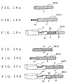
- the electric wire 23 having been colored as shown in FIG.18(a) is supplied to a wire stocking unit 10b. Then, a covering portion of an end portion 3a is removed as shown in FIG.18(b) in the cutting step. Subsequently, the above mark 20 is formed in either the cutting step or the joining steps, that is, in either the cutting unit 11a or the joining unit 12a (that is, marking is carried out on the end portion). As shown in FIG.18(c), the electric wire 23 with a terminal fitting 6 at the end portion 3a thereof is obtained.
- the electric wire 23 is colored by using the painting device 16. Then, as shown in FIG.19(a), the electric wire 33 with a stripe pattern in the colors P,R is obtained. The covering portion of the end portion 3a is removed at the cutting step as shown in FIG.19(b).
- the above mark 20 is formed in either the cutting step or the joining steps, that is, in either the cutting unit 11a or the joining unit 12a (that is, marking is carried out on the end portion).
- the electric wire 3 with the terminal fitting 6 at the end portion 3 a thereof is obtained.
- the electric wire 33 shown in FIG.19(b) is conveyed to the cutting unit 11b and the joining unit 12b. And then, the electric wire 33 with the terminal fitting 6 at the end portion 3a thereof but without a mark is obtained as shown in FIG.19(c).
- the painting devices 16,17,18,19 to color the electric wire 3 are attached only to the wire stocking unit 10a, the cutting unit 11a, and the joining unit 12a.
- the painting devices 16,17,18,19 to color the electric wire 3 need not to be provided on all the wire stocking units 10a,10b, the cutting units 11a, 11b, and the joining units 12a,12b. Therefore, the number of the painting devices 16,17,18,19 can be reduced, and the space for the wiring harness manufacturing apparatus 1 can be reduced, thereby reducing the production cost of the wiring harness 2.
- the color and the marking of the electric wires 3,23,33,43 are not used for indicating the steps for assembling the wiring harness 2 as shown in FIG.10 - FIG.13,FIG.18,FIG,19.
- the color and the marking of the electric wires 3,23,33,43 ware used for indicating the kind of electric wire and the electric or electronic system in which the wiring harness 2 is used.
- Various electric wires 3,23,33,43 shown in FIG.10 - FIG.13,FIG.18,FIG,19 can be made by using the above-described wiring harness manufacturing apparatus 1.
- the coloring of the electric wire 3 by the painting devices 14,15,16,17,18,19 can be carried out at any step of cutting the electric wire 3, removing the covering portion, attaching the terminal fitting 6, and inserting the terminal fitting 6.
- the coloring of the electric wire 3 by the painting devices 14,15,16,17,18,19 is carried out just after any of the above steps.
- the mark 20 is formed on the electric wires 3,23 in either the cutting step or the joining step.
- the mark 20 may not be formed on the electric wires 3,23 in both the cutting step and the joining step.
- the units 10a, 11a, 12a are provided with some of the painting devices 14,15,16,17,18,19.
- the painting devices 14,15,16,17,18,19 may be provided on any one (one portion) of the units 10a, 10b, 11a, 11b, 12a, 12b. That is, the painting devices 14,15,16,17,18,19 may be provided on at least one of the wire stocking unit 10a and the cutting unit 11a.
- the painting devices 14,15,16,17,18,19 may be provided on at least one of the wire stocking unit 10a, the cutting unit 11a, and the joining unit 12a.
- the electric wire is colored in at least one of the wire stocking step and the cutting step.
- the device to color the electric wire needs not to be attached to all the units to carry out the wire stocking step and the cutting step. Therefore, the number of the device to color the electric wire can be reduced, and a space for the apparatus for carrying put the wiring harness manufacturing method can be reduced.
- the electric wire is not necessarily colored in all the steps, all the electric wires need not to be conveyed to the devices to color the electric wire from the units to carry out the wire stocking step and the cutting step. Therefore, the conveying work of the electric wires can be reduced, and production efficiency for manufacturing the wiring harness can be improved, thereby reducing the production cost of the wiring harness.
- the electric wire is colored in a step for assembling the wiring harness. Therefore, the article number (the kind of color of the outer surface) of the electric wire stocked by the wire stocking units can be reduced. Therefore, trouble of controlling the electric wire can be reduced, which could prevent the article number from being mistaken during the assembly of the wiring harness. Therefore, the yield of the wiring harness can be improved.
- the electric wire is colored in at least one of the wire cutting step and the joining step.
- the device to color the electric wire needs not to be attached to all the units to carry out the wire cutting step and the joining step. Therefore, the number of the device to color the electric wire can be reduced, and a space for the apparatus for carrying put the wiring harness manufacturing method can be reduced.
- the electric wire is not necessarily colored in all the steps, all the electric wires need not to be conveyed to the devices to color the electric wire from the units to carry out the wire stocking step, the cutting step, and the joining step. Therefore, the conveying work of the electric wires can be reduced, and production efficiency for manufacturing the wiring harness can be improved, thereby reducing the production cost of the wiring harness.
- the electric wire is colored in a step for assembling the wiring harness. Therefore, the article number (the kind of color of the outer surface) of the electric wire stocked by the wire stocking units can be reduced. Therefore, trouble of controlling the electric wire can be reduced; which could prevent the article number from being mistaken during the assembly of the wiring harness. Therefore, the yield of the wiring harness can be improved.
- the coloring means to color the electric wire are attached to one of the wire stocking units and the cutting units.
- the coloring means- need not to be provided on all the wire stocking units and the cutting units. Therefore, the number of the coloring means can be reduced, and the space for the wiring harness manufacturing apparatus can be reduced, thereby reducing the production cost of the wiring harness.
- the electric wire is colored by the coloring means in a step for assembling the wiring harness. Therefore, the article number (the kind of color of the outer surface) of the electric wire stocked by the wire stocking units can be reduced. Therefore, trouble of controlling the electric wire can be reduced, which could prevent the article number from being mistaken during the assembly of the wiring harness. Therefore, the yield of the wiring harness can be improved.
- the coloring means to color the electric wire are attached to one of the wire stocking units, the cutting units, and the joining units.
- the coloring means need not to be provided on all the wire stocking units, the cutting units, and the joining units. Therefore, the number of the coloring means can be reduced; and the space for the wiring harness manufacturing apparatus can be reduced, thereby reducing the production cost of the wiring harness.
- the electric wire is colored by the coloring means in a step for assembling the wiring harness. Therefore, the article number (the kind of color of the outer surface) of the electric wire stocked by the wire stocking units can be reduced. Therefore, trouble of controlling the electric wire can be reduced, which could prevent the article number from being mistaken during the assembly of the wiring harness. Therefore, the yield of the wiring harness can be improved.
Abstract
Description
- The present invention relates to a wiring harness manufacturing method and a wiring harness manufacturing apparatus for manufacturing a wiring harness arranged on a motor vehicle.
- Various kinds of electronic equipment are carried on a motor vehicle. Therefore, the wiring harness is arranged on the motor vehicle so that electric power from a power source and control signals from a computer can be supplied to the electronic equipment. The wiring harness has electric wires and connectors attached to end portions of the electric wires.
- The electric wire has a conductive core wire and an insulative covering portion covering the conductive core wire. The electric wire is a so-called covered or sheathed wire. The connector has a conductive terminal fitting and an insulative connector housing. The terminal fitting is attached to an end portion of the electric wire and is electrically-connected with the core wire of the electric wire. The connector housing is formed in a box-shape and accommodates the terminal fittings.
- When the wiring harness is manufactured or assembled, the electric wire is firstly cut in a fixed length, and the terminal fitting is attached to the end portion of the electric wire. The electric wires are connected as the need arises. Subsequently, the terminal fitting is inserted into the connector housing. Like this, the above-described wiring harness is manufactured or assembled.
- With regard to the electric wire of the wiring harness, the thickness of the core wire, material (for example, from view point of heat-resistance) of the covering portion, and service conditions should be distinguished. Here, the service conditions mean systems such as an air-bag system, an antilock brake system, and a power transmission system in which the electric wires are used.
- The electric wires of the wiring harness are variously colored and marked for distinguishing the above systems. When the prior art wiring harness is manufactured, the above coloring and marking are carried out in a process of manufacturing the electric wire by forming the core wire from conductive metal such as copper.
- On the other hand, various demands arise from users for the motor vehicle. That is, the motor vehicle is expected to have various kinds of electronic equipment. Consequently, the wiring harness sometimes consists of not less than 100 kinds of the electric wires. Therefore, a factory to manufacture or assemble the wiring harness has to stock not less than 100 kinds of electric wires, while making the stock control of the electric wires having each article number. And therefore, the cost for stocking the electric wires tends to increase.
- Further, for example, the electric wire with a determined article number needs to be set in a device to cut off the electric wire in a fixed length. However, since there exists a lot of article numbers of the electric wires, a mistake in the article number of the electric wire would arise. Therefore, the yield of the wiring harness is reduced, thereby causing reduction of the productive efficiency of the wiring harness.
- In order to solve such problems, the applicant of the present invention has suggested a wiring harness manufacturing method described in Japanese Patent Application Laid-open No.61-245412. In this wiring harness manufacturing method, the electric wires are colored and marked just before each of the wire manufacturing step, the cutting step, the cover removing step, the terminal-crimping step, and the case insertion step.
- With respect to the above prior art wiring harness manufacturing method of Japanese Patent Application Laid-open No.61-245412, however, the coloring and the marking are carried out just before each of the steps of manufacturing or assembling the wiring harness as above.
- Therefore, in the wiring harness manufacturing method of Japanese Patent Application Laid-open No.61-245412, a device for coloring and marking the electric wire has to be provided on each of a wire cutting unit, a covering portion removing unit, a terminal crimping unit, and a terminal inserting unit. The prior art wiring harness manufacturing method also requires installation or mounting work of the above coloring and marking device between each two units, and requires the wiring harness to be set on each coloring and marking device.
- Like this, in the wiring harness manufacturing method of Japanese Patent Application Laid-open No.61-245412, the number of the coloring and marking device increases, which therefore increases the space for manufacturing the wiring harness.
- And also, the coloring and marking work totally requires long time, which lowers the productive efficiency of the wiring harness. Like this, the wiring harness manufacturing method of Japanese Patent Application Laid-open No.61-245412 requires high manufacturing costs of the wiring harness.
- In view of the foregoing, an object of the present invention is to provide a wiring harness manufacturing method and a wiring harness manufacturing apparatus, wherein the above drawbacks of the prior art wiring harness manufacturing method and apparatus have been solved and therefore manufacturing costs of the wiring harness can be reduced.
- In the present invention, a wiring harness manufacturing method for assembling a wiring harness having electric wires and connectors attached to the electric wires comprises the steps of: a wire stocking step to stock the electric wires; and a cutting step to cut an electric wire stocked in the wire stocking step in a desirable length and to attach a terminal fitting of the connector to the electric wire, wherein, an outer surface of the electric wire is colored in at least one of the wire stocking step and the cutting step.
- Like this, the electric wire is colored in at least one of the wire stocking step and the cutting step. Like this, since the electric wire is not necessarily colored in all the steps, the device to color the electric wire needs not to be attached to all the units to carry out the wire stocking step and the cutting step.
- And, because the electric wire is not necessarily colored in all the steps, all the electric wires need not to be conveyed to the devices to color the electric wire from the units to carry out the wire stocking step and the cutting step. Further, the electric wire is colored in a step for assembling the wiring harness. Therefore, the article number (the kind of color of the outer surface) of the electric wire stocked by the wire stocking units can be reduced.
- In this specification, "to color the outer surface of the electric wire" means to color the outer surface of the covering portion of the electric wire with a colorant. The colorant is a liquid substance in which color material (organic substance for industry) is dissolved and dispersed in water or in other solvent. As the organic substance, there exists dyes and pigments (mostly organic substance and synthetic material). In the present specification, "colorant" means both paint and coloring liquid.
- In the coloring liquid, the dye is dissolved or dispersed in the solvent. In the paint, the pigment is dispersed in the dispersion liquid. Therefore, when the outer surface of the covering portion is colored by the coloring liquid, the dye soaks into in the covering portion, and when the outer surface of the covering portion is colored by the paint, the pigment adheres to the outer surface without soaking into the covering portion. That is, "to color the outer surface of the covering portion of the electric wire" in the present specification means to dye the outer surface of the covering portion of the electric wire 'with the dye and also to paint the pigment on the outer surface of the covering portion of the electric wire.
- And, the solvent and the dispersion liquid should have an affinity for synthetic resin forming the covering portion of the electric wire so that the dye securely soaks into the covering portion of the electric wire and the pigment securely adheres to the outer surface of the covering portion of the electric wire.
- In the present invention, a wiring harness manufacturing method for assembling a wiring harness having electric wires and connectors attached to the electric wires comprises the steps of: a wire stocking step to stock the electric wires; and a cutting step to cut an electric wire stocked in the wire stocking step in a desirable length and to attach a terminal fitting of the connector to the electric wire, a joining step to connect the electric wires which have been cut in desirable lengthes by the cutting step and to which the respective terminal fittings have been attached, wherein, an outer surface of the electric wire is colored in both the wire stocking step and one of the cutting step and the joining step.
- Like this, the electric wire is colored in at least one of the wire cutting step and the joining step. Like this, since the electric wire is not necessarily colored in all the steps, the device to color the electric wire needs not to be attached to all the units to carry out the wire cutting step and the joining step.
- And, because the electric wire is not necessarily colored in all the steps, all the electric wires need not to be conveyed to the devices to color the electric wire from the units to carry out the wire stocking step, the cutting step, and the joining step. Further, the electric wire is colored in a step for assembling the wiring harness. Therefore, the article number (the kind of color of the outer surface) of the electric wire stocked by the wire stocking units can be reduced.
- In the present invention, a wiring harness manufacturing apparatus for assembling a wiring harness having electric wires and connectors attached to the electric wires comprises: wire stocking units each to stock the electric wires; and cutting units each to cut the electric wires stocked in the wire stocking units in desirable lengthes and to attach terminal fittings of the connectors to the respective electric wires, wherein, a coloring means to color an outer surface of each of the electric wires is attached to one of the wire stocking units and the cutting units.
- Like this, the coloring means to color the electric wire are attached to one of the wire stocking units and the cutting units. Like this, the coloring means need not to be provided on all the wire stocking units and the cutting units. And, the electric wire is colored by the coloring means in a step for assembling the wiring harness. Therefore, the article number (the kind of color of the outer surface) of the electric wire stocked by the wire stocking units can be reduced.
- In the present invention, a wiring harness manufacturing apparatus for assembling a wiring harness having electric wires and connectors attached to the electric wires comprises: wire stocking units each to stock the electric wires; and cutting units each to cut the electric wires stocked in the wire stocking units in desirable lengthes and to attach terminal fittings of the connectors to the respective electric wires; and joining units to connect the electric wires which have been cut in desirable lengthes by the cutting units and to which the respective terminal fittings have been attached, wherein, a coloring means to color an outer surface of each of the electric wires is attached to one of the wire stocking units, the cutting units, and the joining units.
- Like this, the coloring means to color the electric wire are attached to one of the wire stocking units, the cutting units, and the joining units. Like this, the coloring means need not to be provided on all the wire stocking units, the cutting units, and the joining units. And, the electric wire is colored by the coloring means in a step for assembling the wiring harness. Therefore, the article number (the kind of color of the outer surface) of the electric wire stocked by the wire stocking units can be reduced.
-
- FIG.1. is a block diagram showing the structure of a wiring harness manufacturing apparatus in accordance with the first embodiment of the present invention.
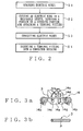
- FIG.2 is a flowchart for manufacturing a wiring harness by using the wiring harness manufacturing apparatus shown in FIG.1.
- FIG.3(a) is an explanatory illustration of a painting device attached to a wire stocking unit of the wiring harness manufacturing apparatus shown in FIG.1.
- FIG.3(b) is an explanatory illustration of an electric wire colored by the painting device of FIG.3(a).
- FIG.4(a) is an explanatory illustration of another painting device attached to the wire stocking unit of the wiring harness manufacturing apparatus shown in FIG.1.
- FIG.4(b) is an explanatory illustration of an electric wire colored by the painting device of FIG.4(a).
- FIG.5(a) is an explanatory illustration of still another painting device attached to the wire stocking unit of the wiring harness manufacturing apparatus shown in FIG.1. FIG.5(b) is an explanatory illustration of an electric wire colored by the painting device of FIG.5(a).
- FIG.6(a) is an explanatory illustration of a painting device attached to a cutting unit of the Wiring harness manufacturing apparatus shown in FIG.1. FIG.6(b) is an explanatory illustration of an electric wire colored by the painting device of FIG.6(a).
- FIG.7(a) is an explanatory illustration of an example of a painting device attached to a cutting unit and a joining unit of the wiring harness manufacturing apparatus shown in FIG.1. FIG.7(b) is an explanatory illustration of an electric wire colored by the painting device of FIG.7(a).
- FIG.8(a) is an explanatory illustration of another example of a painting device attached to a cutting unit and a joining unit of the wiring harness manufacturing apparatus shown in FIG.1. FIG.8(b) is an explanatory illustration of an electric wire colored by the painting device of FIG.8(a).
- FIG.9 is a block diagram showing wiring harness manufacturing steps, using the wiring harness manufacturing apparatus shown in FIG.1, and rough appearances the electric wires.
- FIG.10(a) is an explanatory illustration showing a first example of an electric wire to be assembled by using the wiring harness manufacturing apparatus shown in FIG.1. FIG.10(b) is an explanatory illustration showing the electric wire whose covering portion has been partly removed. FIG.10(c) is an explanatory illustration showing the electric wire to which a terminal fitting is attached.
- FIG.11(a) is an explanatory illustration showing a second example of an electric wire to be assembled by using the wiring harness manufacturing apparatus shown in FIG.1. FIG.11(b) is an explanatory illustration showing the electric wire whose covering portion has been partly removed. FIG.11(c) is an explanatory illustration showing the electric wire to which a terminal fitting is attached.
- FIG.12(a) is an explanatory illustration showing a third example of an electric wire to be assembled by using the wiring harness manufacturing apparatus shown in FIG.1. FIG.12(b) is an explanatory illustration showing the electric wire whose covering portion has been partly removed. FIG. 12(c) is an explanatory illustration showing the electric wire to which a terminal fitting is attached. FIG.12(d) is an explanatory illustration showing the electric wire on which a mark is put and to which a terminal fitting is attached.
- FIG.13(a) is an explanatory illustration showing a fourth example of an electric wire to be assembled by using the wiring harness manufacturing apparatus shown in FIG.1. FIG.13(b) is an explanatory illustration showing the electric wire whose covering portion has been partly removed. FIG. 13(c) is an explanatory illustration showing the electric wire to which a terminal fitting is attached. FIG.13(d) is an explanatory illustration showing the electric wire on which a mark is put and to which a terminal fitting is attached.
- FIG.14 is a schematic illustration showing the structure of the wiring harness assembled by the wiring harness manufacturing apparatus shown in FIG.I.
- FIG.15 is a block diagram showing the structure of a wiring harness manufacturing apparatus in accordance with the second embodiment of the present invention.
- FIG.16 is a flowchart for manufacturing a wiring harness by using the wiring harness manufacturing apparatus shown in FIG.15.
- FIG.17 is a block diagram showing wiring harness manufacturing steps, using the wiring harness manufacturing apparatus shown in FIG.15, and rough appearances the electric wires.
- FIG.18(a) is an explanatory illustration showing an example of an electric wire to be assembled by using the wiring harness manufacturing apparatus shown in FIG.15. FIG:18(b) is an explanatory illustration showing the electric wire whose covering portion has been partly removed. FIG.18(c) is an explanatory illustration showing the electric wire to which a terminal fitting is attached.
- FIG.19(a) is an explanatory illustration showing another example of an electric wire to be assembled by using the wiring harness manufacturing apparatus shown in FIG.15. FIG.19(b) is an explanatory illustration showing the electric wire whose covering portion has been partly removed. FIG.19(c) is an explanatory illustration showing the electric wire to which a terminal fitting is attached.
- FIG.19(d) is an explanatory illustration showing the electric wire on which a mark is put and to which a terminal fitting is attached.
-
- The first embodiment of the inventive wiring harness manufacturing method and wiring harness manufacturing apparatus will now be described in further detail with reference to FIGS.1 - 14. A wiring
harness manufacturing apparatus 1, shown in FIG.1, in accordance with the first embodiment manufactures or assembles awiring harness 2 shown in FIG. 14. - The
wiring harness 2 is arranged on a motor vehicle. Thewiring harness 2 haselectric wires 3,connectors 4, and joint-terminals 5 as shown in FIG.14. Theelectric wire 3 is a covered wire having a conductive core wire and an insulative covering portion covering the core wire. Theelectric wires 3 are bundled. - The
connector 4 has a conductiveterminal fitting 6 and an insulative connector housing 7. Theterminal fitting 6 is formed by bending a conductive sheet metal. Theterminal fitting 6 is attached to anend portion 3a of theelectric wire 3. Theterminal fitting 6 is electrically-connected with the core wire of theelectric wire 3. The connector housing 7 is formed in a box-shape. The connector housing 7 accommodates theterminal fitting 6. Like this, theterminal fitting 6 is attached to the connector housing 7. - The joint-
terminal 5 is made of conductive sheet metal. The joint-terminal 5 electrically-connects core wires of the respectiveelectric wires 3. At the connecting portion of theelectric wires 3, the covering portions of theelectric wires 3 are removed, and the core wires are exposed. The joint-terminal 5 covers the exposed core wires. The joint-terminal 5 crimps the core wires of theelectric wires 3, thereby electrically-connecting theelectric wires 3. - In the
wiring harness 2 of the above structure, theelectric wires 3 have been cut off in desirable lengthes, and the covering portions of theend portions 3a have been removed. Theterminal fittings 6 are crimped to the core wires exposed from theend portions 3a. The covering portions of the connecting portion of theelectric wires 3a are removed. The core wires exposed from the connecting portion are crimped by the joint-terminal 5 so as to connect theelectric wires 3. Theterminal fitting 6 is inserted into, and attached to, the connector housing 7. - Like this, the
wiring harness 2 of the above structure is assembled. Thewiring harness 2 connects a plurality of electronic equipment mounted on a motor vehicle by coupling theabove connectors 4 with mating connectors of the electronic equipment. Thewiring harness 2 supplies electric power or transmits control signals to the electronic equipment. - The wiring
harness manufacturing apparatus 1 assembles or manufactures thewiring harness 2 of the above structure. The wiringharness manufacturing apparatus 1 haswire stocking units 10, cutting units 11, joining units 12 andcase insertion unit 13 as shown in FIG.1. In the embodiment shown in FIG.1, the wiringharness manufacturing apparatus 1 has a pair ofwire stocking units 10, a pair of cutting units 11 and a pair of joining units 12. - The
electric wire 3 is supplied to thewire stocking unit 10 from awire manufacturing apparatus 9. Theelectric wire 3 is, for example, rolled on a real. Thewire manufacturing apparatus 9 makes the above core wire from conductive metal such as copper. The core wire is covered with insulative synthetic resin by thewire manufacturing apparatus 9. The covering portion of theelectric wire 3 made by thewire manufacturing apparatus 9 is in a non-colored state. That is, a non-coloredelectric wire 3 is supplied to thewire stocking unit 10. Here, the non-coloredelectric wire 3 has the covering portion of synthetic resin in which colorant is not put. That is, the covering portion of the non-coloredelectric wire 3 has a color of synthetic resin itself., - In this specification, "to color the outer surface of the
electric wire 3" means to color the outer surface of the covering portion of theelectric wire 3 with a colorant. The colorant is a liquid substance in which color material (organic substance for industry) is dissolved and dispersed in water or in other solvent. As the organic substance, there exists dyes and pigments (mostly organic substance and synthetic material). In the present specification, "colorant" means both paint and coloring liquid. - In the coloring liquid, the dye is dissolved or dispersed in the solvent. In the paint, the pigment is dispersed in the dispersion liquid. Therefore, when the outer surface of the covering portion is colored by the coloring liquid, the dye soaks into in the covering portion, and when the outer surface of the covering portion is colored by the paint, the pigment adheres to the outer surface without soaking into the covering portion. That is, "to color the outer surface of the covering portion of the electric wire" in the present specification means to dye the outer surface of the covering portion of the
electric wire 3 with the dye and also to paint the pigment on the outer surface of the covering portion of theelectric wire 3. - And, the solvent and the dispersion liquid should have an affinity for synthetic resin forming the covering portion of the
electric wire 3 so that the dye securely soaks into the covering portion of theelectric wire 3 and the pigment securely adheres to the outer surface of the covering portion of theelectric wire 3. - The
wire stocking unit 10 once stocks theelectric wire 3 supplied from thewire manufacturing apparatus 9. Thepainting devices painting devices electric wire 3 differently from a color of synthetic resin of the covering portion. - Each of the pair of wire stocking units 10a,10b supplies the
electric wires 3 to the respective cutting units 11. Theelectric wire 3 supplied to the cutting unit 11 is in a state of being rolled on a reel. The cutting unit 11 cuts off theelectric wire 3 in a desirable length. The cutting unit 11 removes the covering portions of theend portions 3a of theelectric wire 3. The cutting unit 11 attaches theterminal fittings 6 to therespective end portions 3a of theelectric wire 3. - At least one of the
painting devices painting devices painting devices electric wire 3 differently from a color of synthetic resin of the covering portion. - At least one of the
painting devices painting devices painting devices electric wire 3 differently from a color of synthetic resin of the covering portion. - The
electric wire 3, to which theterminal fittings 6 have been attached by the other cutting unit 11b, is supplied to the joining unit 12a from the cutting unit 11b. Theelectric wire 3, to which theterminal fittings 6 have been attached, is supplied to the other joining unit 12b from each of the pair of cutting units 11a, 11b. The joining units 12a, 12b remove the covering portions of the above-described connecting portions of theelectric wires 3 and crimp the core wires with the joint-terminal 5 so as to connect theelectric wires 3. - The
electric wire 3 with theterminal fitting 6 is supplied to thecase insertion unit 13 from each of the pair of joining units 12a,12b. Thecase insertion unit 13 inserts theterminal fitting 6 attached to theend portion 3 a of theelectric wire 3 into the connector housing 7, thereby assembling theconnector 4. - The painting-
device 14 has an apparatus body 14a, a pair ofrollers 14b, a plurality ofsprayers 14c and adryer 14d as shown in FIG.3(a). The pair ofrollers 14b are arranged with some interval, and theelectric wire 3 is arranged between therollers 14b. - A pair of
sprayers 14c are provided in the illustrated embodiment. Thesprayer 14c sprays the colorant toward theelectric wire 3 traveling between therollers 14b. The pair ofsprayers 14c color the outer surface of theelectric wire 3 over the whole periphery thereof. The sprayers 14c color the outer surface of theelectric wire 3 differently from a color of synthetic resin of the covering portion over the whole periphery of theelectric wire 3. - The drier 14d is arranged downstream of the sprayers 14c in a traveling direction of the
electric wire 3. The drier 14d dries the colorant blown on the outer surface of theelectric wire 3 by thesprayers 14c. Thepainting device 14 of the above structure colors the outer surface of theelectric wire 3 in a color P (a hatched portion in FIG.3(b)) different from a color of synthetic resin of the covering portion over the whole periphery of theelectric wire 3. - The
painting device 15 has a pair ofrollers 15a,sprayers 15b andmarkers 15c as shown in FIG.4(a). The pair ofrollers 15a are arranged with some interval, and theelectric wire 3 is arranged between therollers 15a. - A pair of
sprayers 15b are provided in the illustrated embodiment. Thesprayer 15b sprays the colorant toward theelectric wire 3 traveling between therollers 15a. The sprayers 15b color the outer surface of theelectric wire 3. The sprayers 15b color the outer surface of theelectric wire 3 differently from a color of synthetic resin of the covering portion over the whole periphery of theelectric wire 3. - A pair of
markers 15c are provided in the illustrated embodiment. Themarkers 15c are arranged downstream of the sprayers 15b in a traveling direction of theelectric wire 3. Themarker 15c puts the colorant partly on the outer surface of theelectric wire 3, which colorant has a color different from both the color colored by thesprayer 15b and the color of the covering portion. - In the
painting device 15 of the above structure, thesprayer 15b colors the outer surface of theelectric wire 3 in a color P (a hatched portion in FIG.4(b)) different from a color of synthetic resin of the covering portion over the whole periphery of theelectric wire 3. And then, themarker 15c colors the outer surface, having been colored by thesprayer 15b, in a color R different from the color P and the color of the covering portion itself. Thepainting device 15 colors the outer surface of theelectric wire 3 in a pattern of stripe of the colors P,R as shown in FIG.4(b). - The
painting device 16 has a pair ofrollers 16a and a plurality ofmarkers 16b as shown in FIG.5(a). The pair ofrollers 16a are arranged with some interval, and theelectric wire 3 is arranged between therollers 16a. - A pair of
markers 16b are provided in the illustrated embodiment. Themarker 16b partly put a colorant on the outer surface of theelectric wire 3. The pair ofmarkers 16b partly color the outer surface of theelectric wire 3 differently from a color of synthetic resin of the covering portion. - In the
painting device 16 of the above structure, themarker 16b partly colors the outer surface of theelectric wire 3 in a color R (a hatched portion in FIG.5(b)) different from a color of synthetic resin of the covering portion. Thepainting device 16 colors the outer surface of theelectric wire 3 in a pattern of stripe of the color R as shown in FIG.5(b). - The
painting device 17 has a pair of runningrollers 17a, atubular member 17b and acoloring unit 17c as shown in FIG.6(a). The pair of runningrollers 17a put theelectric wire 3 therebetween and make theelectric wire 3 run. - The
tubular member 17b is formed tubularly in order to receive theend portion 3a of theelectric wire 3. Thetubular member 17b is provided with a through-hole 17d. Thecoloring unit 17c partly puts a colorant on the outer surface of theelectric wire 3 in thetubular member 17b through the through-hole 17d. Thecoloring unit 17c partly colors the outer surface of theelectric wire 3 differently from a color of synthetic resin of the covering portion (that is, marking is carried out on the end portion). - In the
painting device 17 of the above structure, thecoloring unit 17c partly colors the outer surface of theelectric wire 3 in a color S (a hatched portion in FIG.6(b)) different from the colors P,R. Thepainting device 17 partly colors the outer surface of theelectric wire 3 in the color S so as to form amark 20 as shown in FIG.6(b). - The
painting device 18 has wire clampers 18a andsprayers 18b as shown in FIG.7(a). The wire clamper 18a clamps theend portion 3a of theelectric wire 3. Thesprayer 18b partly sprays a colorant on the outer surface of theend portion 3a of theelectric wire 3. Thesprayer 18b partly colors the outer surface of theelectric wire 3 differently from a color of synthetic resin of the covering portion (that is, marking is carried out on the end portion). - In the
painting device 18 of the above structure, thesprayer 18b partly colors the outer surface of theelectric wire 3 in a color S (a hatched portion in FIG.7(b)) different from the colors P,R. Thepainting device 18 partly colors the outer surface of theelectric wire 3 in the color S so as to form amark 20 as shown in FIG.7(b). - The
painting device 19 has wire clampers 19a and astamper 19b as shown in FIG.8(a). The wire clamper 19a has holdingmembers end portion 3a of theelectric wire 3 between the holdingmembers - The
stamper 19b moves relative to theend portion 3a of theelectric wire 3 along with the holdingmembers stamper 19b approaches theend portion 3a of theelectric wire 3 when the holdingmembers stamper 19b is put into contact with theend portion 3a and partly puts a colorant on the outer surface of theend portion 3a. Thestamper 19b partly colors the outer surface of theelectric wire 3 differently from a color of synthetic resin of the covering portion (that is, marking is carried out on the end portion). - In the
painting device 19 of the above structure, thestamper 19b partly colors the outer surface of theelectric wire 3 in a color S (a hatched portion in FIG.8(b)) different from the colors P,R Thepainting device 19 partly colors the outer surface of theelectric wire 3 in the color S so as to form amark 20 as shown in FIG.8(b). - When the
wiring harness 2 is manufactured by using the above wiringharness manufacturing apparatus 1, theelectric wire 3 wound up on a reel is firstly stocked once in each of the wire stocking units 10a, 10b at Step S1 as a wire stocking step in FIG.2 and FIG.9. - The wire stocking unit 10a colors the outer surface of the
electric wire 3 over the whole periphery thereof by using thepainting device 14, forms (colors) a stripe pattern on the outer surface of theelectric wire 3 by using thepainting device 15, or forms (colors) a stripe pattern on the outer surface of theelectric wire 3 by using thepainting device 16. And then, Step S2 (shown in FIG.2 and FIG.9) as a cutting step is reached. - In Step S2, the
electric wires 3 are conveyed toward the cutting units 11a, 11b from the wire stocking units 10a,10b. The cutting units 11a, 11b cut off theelectric wires 3 in desirable lengthes, remove the covering portions of theend portions 3a, and attach theterminal fittings 6 to theend portions 3a. - The cutting unit 11a forms the
mark 20 on theend portion 3a of theelectric wire 3 by using one of thepainting devices - In Step S3, the
electric wire 3 is conveyed toward the joining unit 12b from the cutting unit 11a, and theelectric wires 3 are conveyed toward the joining units 12a, 12b from the cutting unit 11b. The joining units 12a,12b remove the covering portions of the connecting portions of theelectric wires 3 and connect theelectric wires 3 with the joint-terminal 5. - The joining unit 12a forms the
mark 20 on theend portion 3a of theelectric wire 3 by using one of thepainting devices 18,19 (that is, marking is carried out on the end portion). And then, Step S4 (shown in FIG.2 and FIG.9) as a case insertion step is reached. - In Step S4, the
electric wires 3 are conveyed toward thecase insertion unit 13 from the joining units 12a,12b. Thecase insertion unit 13 inserts theterminal fitting 6 attached to theend portion 3a of theelectric wire 3 into the connector housing 7. Like this, the wiringharness manufacturing apparatus 1 assembles thewiring harness 2. - As above, when the non-colored
electric wire 3 shown in FIG.10(a) is supplied to the wire stocking unit 10b, the covering portion of theend portion 3 a is removed as shown in FIG.10(b) at the cutting step. Subsequently, theabove mark 20 is formed in either the cutting step or the joining steps, that is, in either the cutting unit 11a or the joining unit 12a. As shown in FIG.10(c), theelectric wire 3 with theterminal fitting 6 at theend portion 3a thereof is obtained. - Upon the supply of the non-colored
electric wire 3 to the wire stocking unit 10a, theelectric wire 3 is colored by using thepainting device 14. Then, as shown in FIG.11(a), the electric wire 3 (hereinafter, 23) colored in the color P over the whole periphery thereof is obtained. The covering portion of theend portion 3a is removed at the cutting step as shown in FIG.11(b). Subsequently, theabove mark 20 is formed in either the cutting step or the joining steps, that is, in either the cutting unit 11a or the joining unit 12a. As shown in FIG.11(c), theelectric wire 3 with theterminal fitting 6 at theend portion 3a thereof is obtained. - Upon the supply of the non-colored
electric wire 3 to the wire stocking unit 10a, theelectric wire 3 is colored by using thepainting device 15. Then, as shown in FIG. 12(a), the electric wire 3 (hereinafter, 33) with a stripe pattern in the colors P,R is obtained. The covering portion of theend portion 3a is removed at the cutting step as shown in FIG.12(b). - Subsequently, the
above mark 20 is formed in either the cutting step or the joining steps, that is, in either the cutting unit 11a or the joining unit 12a. As shown in FTG.12(d), theelectric wire 3 with theterminal fitting 6 at theend portion 3a thereof is obtained. On the other hand, theelectric wire 33 shown in FIG.12(b) is conveyed to the cutting unit 11b and the joining unit 12b. And then, theelectric wire 33 with theterminal fitting 6 at theend portion 3 a thereof but without a mark is obtained as shown in FIG.12(c). - Upon the supply of the non-colored
electric wire 3 to the wire stocking unit 10a, theelectric wire 3 is colored by using thepainting device 16. Then, as shown in FIG.13(a), the electric wire 3 (hereinafter, 43) with a stripe pattern in the color R is obtained. The covering portion of theend portion 3a is removed at the cutting step as shown in FIG. 13(b). - Subsequently, the
above mark 20 is formed in either the cutting step or the joining steps, that is, in either the cutting unit 11a or the joining unit 12a. As shown in FIG.13(d), theelectric wire 3 with theterminal fitting 6 at theend portion 3a thereof is obtained. On the other hand, theelectric wire 43 shown in FIG.13(b) is conveyed to the cutting unit 11b and the joining unit 12b. And then, theelectric wire 43 with theterminal fitting 6 at theend portion 3a thereof but without a mark is obtained as shown in FIG. 13(c). - According to the present embodiment, as shown in FIG.9, the outer surface of the
electric wire 3 is colored in one of the wire stocking step and the cutting step. And, as shown in FIG.9, the outer surface of theelectric wire 3 is colored in one of the wire stocking step, the cutting step and the joining step. Further, the outer surface of theelectric wire 3 is colored in one of the cutting step and the joining step. Like this, theelectric wire 3 is not necessarily colored in all the steps. Therefore, thepainting devices electric wire 3 need not to be provided on all the wire stocking units 10a, 10b, the cutting units 11a, 11b, and the joining units 12a,12b. Therefore, the number of thepainting devices harness manufacturing apparatus 1 can be reduced. - And, because the
electric wire 3 is not necessarily colored in all the steps, all theelectric wires 3 need not to be conveyed to thepainting devices electric wires 3 can be reduced, and production efficiency for manufacturing thewiring harness 2 can be improved, thereby reducing the production cost of thewiring harness 2. - Further, the
electric wire 3 is colored in a step for assembling thewiring harness 2. Therefore, the article number (the kind of color of the outer surface) of theelectric wire 3 stocked by the wire stocking units 10a, 10b can be reduced. Therefore, trouble of controlling theelectric wire 3 can be reduced, which could prevent the article number from being mistaken during the assembly of thewiring harness 2. Therefore, the yield of thewiring harness 2 can be improved. - The
painting devices electric wire 3 are attached only to the wire stocking unit 10a, the cutting unit 11a, and the joining unit 12a. Like this, thepainting devices electric wire 3 need not to be provided on all the wire stocking units 10a,10b, the cutting units 11a, 11b, and the joining units 12a,12b. Therefore, the number of thepainting devices harness manufacturing apparatus 1 can be reduced, thereby reducing the production cost of thewiring harness 2. - Next, the second embodiment of the inventive wiring harness manufacturing method and wiring harness manufacturing apparatus will now be described in further detail with reference to FIGS.15 - 19. Here, the same references are assigned to the same elements or members as the above first embodiment, and the description thereof is omitted.
- An
electric wire 23 colored in a color P over the whole periphery is supplied from awire manufacturing apparatus 9 to a wiringharness manufacturing apparatus 1 of the present embodiment. Apainting device 16 is attached to a wire stocking unit 10a. - A
wiring harness 2 is assembled through Step S1 to Step S4 shown in FIG. 16 and FIG.17 by using the wiringharness manufacturing apparatus 1, similarly to the above-described first embodiment. - The
electric wire 23 having been colored as shown in FIG.18(a) is supplied to a wire stocking unit 10b. Then, a covering portion of anend portion 3a is removed as shown in FIG.18(b) in the cutting step. Subsequently, theabove mark 20 is formed in either the cutting step or the joining steps, that is, in either the cutting unit 11a or the joining unit 12a (that is, marking is carried out on the end portion). As shown in FIG.18(c), theelectric wire 23 with aterminal fitting 6 at theend portion 3a thereof is obtained. - Upon the supply of the colored
electric wire 23 to the wire stocking unit 10a, theelectric wire 23 is colored by using thepainting device 16. Then, as shown in FIG.19(a), theelectric wire 33 with a stripe pattern in the colors P,R is obtained. The covering portion of theend portion 3a is removed at the cutting step as shown in FIG.19(b). - Subsequently, the
above mark 20 is formed in either the cutting step or the joining steps, that is, in either the cutting unit 11a or the joining unit 12a (that is, marking is carried out on the end portion). As shown in FIG.19(d), theelectric wire 3 with theterminal fitting 6 at theend portion 3 a thereof is obtained. On the other hand, theelectric wire 33 shown in FIG.19(b) is conveyed to the cutting unit 11b and the joining unit 12b. And then, theelectric wire 33 with theterminal fitting 6 at theend portion 3a thereof but without a mark is obtained as shown in FIG.19(c). - According to the present embodiment, similarly to the above-described first embodiment, the
painting devices electric wire 3 are attached only to the wire stocking unit 10a, the cutting unit 11a, and the joining unit 12a. Like this, thepainting devices electric wire 3 need not to be provided on all the wire stocking units 10a,10b, the cutting units 11a, 11b, and the joining units 12a,12b. Therefore, the number of thepainting devices harness manufacturing apparatus 1 can be reduced, thereby reducing the production cost of thewiring harness 2. - Here, the color and the marking of the
electric wires wiring harness 2 as shown in FIG.10 - FIG.13,FIG.18,FIG,19. The color and the marking of theelectric wires wiring harness 2 is used. - Various
electric wires harness manufacturing apparatus 1. Further, in the present invention, the coloring of theelectric wire 3 by thepainting devices electric wire 3, removing the covering portion, attaching theterminal fitting 6, and inserting theterminal fitting 6. Preferably, the coloring of theelectric wire 3 by thepainting devices - Here, in the above first and second embodiments of the wiring
harness manufacturing apparatus 1, themark 20 is formed on theelectric wires mark 20 may not be formed on theelectric wires - Further, in the above-described embodiment, the units 10a, 11a, 12a are provided with some of the
painting devices painting devices painting devices painting devices - As described above, in the present invention set forth in
claim 1, the electric wire is colored in at least one of the wire stocking step and the cutting step. Like this, since the electric wire is not necessarily colored in all the steps, the device to color the electric wire needs not to be attached to all the units to carry out the wire stocking step and the cutting step. Therefore, the number of the device to color the electric wire can be reduced, and a space for the apparatus for carrying put the wiring harness manufacturing method can be reduced. - And, because the electric wire is not necessarily colored in all the steps, all the electric wires need not to be conveyed to the devices to color the electric wire from the units to carry out the wire stocking step and the cutting step. Therefore, the conveying work of the electric wires can be reduced, and production efficiency for manufacturing the wiring harness can be improved, thereby reducing the production cost of the wiring harness.
- Further, the electric wire is colored in a step for assembling the wiring harness. Therefore, the article number (the kind of color of the outer surface) of the electric wire stocked by the wire stocking units can be reduced. Therefore, trouble of controlling the electric wire can be reduced, which could prevent the article number from being mistaken during the assembly of the wiring harness. Therefore, the yield of the wiring harness can be improved.
- In the present invention set forth in
claim 2, the electric wire is colored in at least one of the wire cutting step and the joining step. Like this, since the electric wire is not necessarily colored in all the steps, the device to color the electric wire needs not to be attached to all the units to carry out the wire cutting step and the joining step. Therefore, the number of the device to color the electric wire can be reduced, and a space for the apparatus for carrying put the wiring harness manufacturing method can be reduced. - And, because the electric wire is not necessarily colored in all the steps, all the electric wires need not to be conveyed to the devices to color the electric wire from the units to carry out the wire stocking step, the cutting step, and the joining step. Therefore, the conveying work of the electric wires can be reduced, and production efficiency for manufacturing the wiring harness can be improved, thereby reducing the production cost of the wiring harness.
- Further, the electric wire is colored in a step for assembling the wiring harness. Therefore, the article number (the kind of color of the outer surface) of the electric wire stocked by the wire stocking units can be reduced. Therefore, trouble of controlling the electric wire can be reduced; which could prevent the article number from being mistaken during the assembly of the wiring harness. Therefore, the yield of the wiring harness can be improved.
- In the present invention set forth in
claim 3, the coloring means to color the electric wire are attached to one of the wire stocking units and the cutting units. Like this, the coloring means- need not to be provided on all the wire stocking units and the cutting units. Therefore, the number of the coloring means can be reduced, and the space for the wiring harness manufacturing apparatus can be reduced, thereby reducing the production cost of the wiring harness. - And, the electric wire is colored by the coloring means in a step for assembling the wiring harness. Therefore, the article number (the kind of color of the outer surface) of the electric wire stocked by the wire stocking units can be reduced. Therefore, trouble of controlling the electric wire can be reduced, which could prevent the article number from being mistaken during the assembly of the wiring harness. Therefore, the yield of the wiring harness can be improved.
- In the present invention set forth in
claim 4, the coloring means to color the electric wire are attached to one of the wire stocking units, the cutting units, and the joining units. Like this, the coloring means need not to be provided on all the wire stocking units, the cutting units, and the joining units. Therefore, the number of the coloring means can be reduced; and the space for the wiring harness manufacturing apparatus can be reduced, thereby reducing the production cost of the wiring harness. - And, the electric wire is colored by the coloring means in a step for assembling the wiring harness. Therefore, the article number (the kind of color of the outer surface) of the electric wire stocked by the wire stocking units can be reduced. Therefore, trouble of controlling the electric wire can be reduced, which could prevent the article number from being mistaken during the assembly of the wiring harness. Therefore, the yield of the wiring harness can be improved.
Claims (4)
- A wiring harness manufacturing method for assembling a wiring harness having electric wires and connectors attached to the electric wires, comprising the steps of:wherein, an outer surface of the electric wire is colored in at least one of the wire stocking step and the cutting step.a wire stocking step to stock the electric wires; anda cutting step to cut an electric wire stocked in the wire 'stocking step in a desirable length and to attach a terminal fitting of the connector to the electric wire,
- A wiring harness manufacturing method for assembling a wiring harness having electric wires and connectors attached to the electric wires, comprising the steps of:wherein, an outer surface of the electric wire is colored in both the wire stocking step and one of the cutting step and the joining step.a wire stocking step to stock the electric wires; anda cutting step to cut an electric wire stocked in the wire stocking step in a desirable length and to attach a terminal fitting of the connector to the electric wire,a joining step to connect the electric wires which have been cut in desirable lengthes by the cutting step and to which the respective terminal fittings have been attached,
- A wiring harness manufacturing apparatus for assembling a wiring harness having electric wires and connectors attached to the electric wires, comprising:wherein, a coloring means to color an outer surface of each of the electric wires is attached to one of the wire stocking units and the cutting units.wire stocking units each to stock the electric wires; andcutting units each to cut the electric wires stocked in the wire stocking units in desirable lengthes and to attach terminal fittings of the connectors to the respective electric wires,
- A wiring harness manufacturing apparatus for assembling a wiring harness having electric wires and connectors attached to the electric wires, comprising:wherein, a coloring means to color an outer surface of each of the electric wires is attached to one of the wire stocking units, the cutting units, and the joining units.wire stocking units each to stock the electric wires; andcutting units each to cut the electric wires stocked in the wire stocking units in desirable lengthes and to attach terminal fittings -of the connectors to the respective electric wires; andjoining units to connect the electric wires which have been cut in desirable lengthes by the cutting units and to which the respective terminal fittings have been attached,
Applications Claiming Priority (3)
| Application Number | Priority Date | Filing Date | Title |
|---|---|---|---|
| JP2001256721 | 2001-08-27 | ||
| JP2001256721 | 2001-08-27 | ||
| PCT/JP2002/008557 WO2003019580A1 (en) | 2001-08-27 | 2002-08-26 | Method and device for manufacturing wire harness |
Publications (2)
| Publication Number | Publication Date |
|---|---|
| EP1431983A1 true EP1431983A1 (en) | 2004-06-23 |
| EP1431983A4 EP1431983A4 (en) | 2006-12-06 |
Family
ID=19084499
Family Applications (1)
| Application Number | Title | Priority Date | Filing Date |
|---|---|---|---|
| EP02762853A Withdrawn EP1431983A4 (en) | 2001-08-27 | 2002-08-26 | Method and device for manufacturing wire harness |
Country Status (6)
| Country | Link |
|---|---|
| US (1) | US7296334B2 (en) |
| EP (1) | EP1431983A4 (en) |
| JP (1) | JP4035105B2 (en) |
| CN (1) | CN1296944C (en) |
| MX (1) | MXPA04001820A (en) |
| WO (1) | WO2003019580A1 (en) |
Cited By (1)
| Publication number | Priority date | Publication date | Assignee | Title |
|---|---|---|---|---|
| WO2011108558A1 (en) | 2010-03-02 | 2011-09-09 | Yazaki Corporation | Wiring harness and manufacturing method thereof |
Families Citing this family (14)
| Publication number | Priority date | Publication date | Assignee | Title |
|---|---|---|---|---|
| US7653988B2 (en) * | 2001-12-28 | 2010-02-02 | Yazaki Corporation | Method for order receipt production of electric wire and its order receipt production system |
| JP4431141B2 (en) | 2004-06-07 | 2010-03-10 | 矢崎総業株式会社 | Electric wire coloring apparatus and electric wire coloring method |
| EP1760377B1 (en) | 2004-06-07 | 2012-04-04 | Yazaki Corporation | Electromagnetic valve drive method, electromagnetic valve drive device, and electric cable coloring device |
| JP4426911B2 (en) | 2004-06-25 | 2010-03-03 | 矢崎総業株式会社 | Coloring nozzle |
| JP5049525B2 (en) | 2006-07-10 | 2012-10-17 | 矢崎総業株式会社 | Colored ink for electric wires |
| JP5101844B2 (en) | 2006-08-08 | 2012-12-19 | 矢崎総業株式会社 | Coloring nozzle |
| JP2008078012A (en) * | 2006-09-22 | 2008-04-03 | Yazaki Corp | Electric wire coloring device |
| US8099857B2 (en) | 2008-02-09 | 2012-01-24 | Cirris Systems Corporation | Apparatus for electrical pin installation and retention confirmation |
| JP5362441B2 (en) * | 2008-12-26 | 2013-12-11 | 矢崎総業株式会社 | Electric wire joint part forming apparatus and electric wire joint part forming method |
| US20110079427A1 (en) * | 2009-10-07 | 2011-04-07 | Lakshmikant Suryakant Powale | Insulated non-halogenated covered aluminum conductor and wire harness assembly |
| JP2013149512A (en) * | 2012-01-20 | 2013-08-01 | Yazaki Corp | Method for manufacturing wire harness, and device for manufacturing wire harness |
| JP5567239B1 (en) * | 2013-02-23 | 2014-08-06 | 古河電気工業株式会社 | Connection structure manufacturing method and connection structure manufacturing apparatus |
| US20140311796A1 (en) * | 2013-04-17 | 2014-10-23 | Harco Laboratories, Inc. | Wire harness for high temperature exhaust gas applications |
| CN106363421B (en) * | 2016-12-11 | 2018-07-24 | 东莞市火速自动化科技有限公司 | A kind of wire rod automatic assembling machine |
Citations (2)
| Publication number | Priority date | Publication date | Assignee | Title |
|---|---|---|---|---|
| DE1299336B (en) * | 1964-01-14 | 1969-07-17 | Siemens Ag | Device for the automatic creation of shaped cables for telecommunication systems, in particular telephone systems |
| GB2282339A (en) * | 1993-10-01 | 1995-04-05 | Sumitomo Wall Systems Ltd | Apparatus and method for fabricating harness |
Family Cites Families (17)
| Publication number | Priority date | Publication date | Assignee | Title |
|---|---|---|---|---|
| US4126935A (en) * | 1977-05-31 | 1978-11-28 | Bell Telephone Laboratories, Incorporated | Method and apparatus for manufacturing wiring harnesses |
| US4136440A (en) * | 1977-07-12 | 1979-01-30 | Amp Incorporated | Electrical harness fabrication method and apparatus |
| US4646404A (en) * | 1983-07-07 | 1987-03-03 | Nippon Acchakutanshi Seizo Kabushiki Kaisha | Apparatus for manufacturing electrical harnesses |
| US4603476A (en) * | 1984-03-08 | 1986-08-05 | Tarbox John W | Method for handling harness wire |
| JPH071645B2 (en) * | 1985-04-23 | 1995-01-11 | 矢崎総業株式会社 | Wire harness manufacturing method |
| PT90825B (en) * | 1988-06-13 | 1994-05-31 | Yazaki Corp | PROCESS AND APPARATUS FOR INSERTING WIRING EXTENSIONS THAT SUPPORT TERMINALS INTO A CONNECTOR BOX |
| JPH06105565B2 (en) * | 1989-06-12 | 1994-12-21 | 住友電装株式会社 | Automatic crimping wiring device for wire harness |
| JP2827771B2 (en) * | 1992-11-13 | 1998-11-25 | 住友電装株式会社 | Harness manufacturing apparatus and method of using the same |
| JP3056353B2 (en) * | 1992-12-04 | 2000-06-26 | 矢崎総業株式会社 | Wire harness set type manufacturing method and manufacturing apparatus |
| JP2959322B2 (en) * | 1993-03-09 | 1999-10-06 | 住友電装株式会社 | Harness electric wire manufacturing apparatus and manufacturing method |
| GB9311015D0 (en) | 1993-05-28 | 1993-07-14 | Amp Great Britain | Multi-colour wire marker |
| JPH09161548A (en) * | 1995-12-05 | 1997-06-20 | Harness Sogo Gijutsu Kenkyusho:Kk | Flat wire for wire harness and its manufacture |
| JP3892919B2 (en) * | 1996-10-03 | 2007-03-14 | 矢崎総業株式会社 | Wire harness manufacturing method and manufacturing apparatus |
| JP3358154B2 (en) * | 1997-08-27 | 2002-12-16 | 矢崎総業株式会社 | WIRE HARNESS, ITS MANUFACTURING METHOD AND DEVICE |
| JP3672215B2 (en) * | 1998-03-16 | 2005-07-20 | 矢崎総業株式会社 | Wire harness manufacturing system |
| JP2000340330A (en) * | 1999-05-27 | 2000-12-08 | Harness Syst Tech Res Ltd | Terminal mounting machine and wire harness manufacturing equipment provided with it |
| JP3950278B2 (en) * | 2000-03-14 | 2007-07-25 | 矢崎総業株式会社 | Wire harness manufacturing equipment |
-
2002
- 2002-08-26 WO PCT/JP2002/008557 patent/WO2003019580A1/en active Application Filing
- 2002-08-26 CN CNB028190866A patent/CN1296944C/en not_active Expired - Fee Related
- 2002-08-26 EP EP02762853A patent/EP1431983A4/en not_active Withdrawn
- 2002-08-26 JP JP2003522951A patent/JP4035105B2/en not_active Expired - Fee Related
- 2002-08-26 US US10/487,226 patent/US7296334B2/en not_active Expired - Lifetime
- 2002-08-26 MX MXPA04001820A patent/MXPA04001820A/en active IP Right Grant
Patent Citations (2)
| Publication number | Priority date | Publication date | Assignee | Title |
|---|---|---|---|---|
| DE1299336B (en) * | 1964-01-14 | 1969-07-17 | Siemens Ag | Device for the automatic creation of shaped cables for telecommunication systems, in particular telephone systems |
| GB2282339A (en) * | 1993-10-01 | 1995-04-05 | Sumitomo Wall Systems Ltd | Apparatus and method for fabricating harness |
Non-Patent Citations (1)
| Title |
|---|
| See also references of WO03019580A1 * |
Cited By (2)
| Publication number | Priority date | Publication date | Assignee | Title |
|---|---|---|---|---|
| WO2011108558A1 (en) | 2010-03-02 | 2011-09-09 | Yazaki Corporation | Wiring harness and manufacturing method thereof |
| EP2543047A4 (en) * | 2010-03-02 | 2016-09-14 | Yazaki Corp | Wiring harness and manufacturing method thereof |
Also Published As
| Publication number | Publication date |
|---|---|
| US20050015966A1 (en) | 2005-01-27 |
| EP1431983A4 (en) | 2006-12-06 |
| CN1561526A (en) | 2005-01-05 |
| JP4035105B2 (en) | 2008-01-16 |
| WO2003019580A1 (en) | 2003-03-06 |
| JPWO2003019580A1 (en) | 2004-12-16 |
| US7296334B2 (en) | 2007-11-20 |
| MXPA04001820A (en) | 2004-07-08 |
| CN1296944C (en) | 2007-01-24 |
Similar Documents
| Publication | Publication Date | Title |
|---|---|---|
| US7296334B2 (en) | Method and device for manufacturing wire harness | |
| JP6322377B2 (en) | Wire harness production system and wire harness production method | |
| JP5416358B2 (en) | Wire harness | |
| JP4295621B2 (en) | Order-made production method of wire harness and its production system | |
| US10038292B2 (en) | Method for connecting insulated wires | |
| US7504586B2 (en) | Cable and cable identificating method | |
| JPS61245412A (en) | Manufacture of wire harness | |
| EP1441369B1 (en) | Wire recycling method | |
| JP3215031B2 (en) | Electrical distribution connector and connection method | |
| WO2015050027A1 (en) | Wire harness production system, and wire harness production method | |
| EP1460647B1 (en) | Method for order receipt production of electric wire and its order receipt production system | |
| JP6206663B2 (en) | Wire harness production system and wire harness production method | |
| WO1995005957A1 (en) | Wire harness assembly having color coded wires | |
| US20070298649A1 (en) | Improved ethernet connector | |
| WO2015050085A1 (en) | Wire harness production system, and wire harness production method | |
| WO2004038737A1 (en) | Wire and wire harness order reception and production method, order reception and production system thereof, and wire crosslinking device | |
| JPS60151906A (en) | Method of marking identification to coated wire | |
| JP2003303524A (en) | Method for manufacturing electric wire | |
| WO2014013988A1 (en) | Method for manufacturing joint connectors | |
| JP2014038852A (en) | Wiring harness |
Legal Events
| Date | Code | Title | Description |
|---|---|---|---|
| PUAI | Public reference made under article 153(3) epc to a published international application that has entered the european phase |
Free format text: ORIGINAL CODE: 0009012 |
|
| 17P | Request for examination filed |
Effective date: 20040227 |
|
| AK | Designated contracting states |
Kind code of ref document: A1 Designated state(s): AT BE BG CH CY CZ DE DK EE ES FI FR GB GR IE IT LI LU MC NL PT SE SK TR |
|
| AX | Request for extension of the european patent |
Extension state: AL LT LV MK RO SI |
|
| A4 | Supplementary search report drawn up and despatched |
Effective date: 20061107 |
|
| RAP1 | Party data changed (applicant data changed or rights of an application transferred) |
Owner name: YAZAKI CORPORATION |
|
| 17Q | First examination report despatched |
Effective date: 20100330 |
|
| STAA | Information on the status of an ep patent application or granted ep patent |
Free format text: STATUS: THE APPLICATION IS DEEMED TO BE WITHDRAWN |
|
| 18D | Application deemed to be withdrawn |
Effective date: 20160518 |