Technical Field
The present invention relates to a wiring harness manufacturing method and a
wiring harness manufacturing apparatus for manufacturing a wiring harness
arranged on a motor vehicle.
Background Art
Various kinds of electronic equipment are carried on a motor vehicle.
Therefore, the wiring harness is arranged on the motor vehicle so that electric
power from a power source and control signals from a computer can be supplied to
the electronic equipment. The wiring harness has electric wires and connectors
attached to end portions of the electric wires.
The electric wire has a conductive core wire and an insulative covering portion
covering the conductive core wire. The electric wire is a so-called covered or
sheathed wire. The connector has a conductive terminal fitting and an insulative
connector housing. The terminal fitting is attached to an end portion of the
electric wire and is electrically-connected with the core wire of the electric wire.
The connector housing is formed in a box-shape and accommodates the terminal
fittings.
When the wiring harness is manufactured or assembled, the electric wire is
firstly cut in a fixed length, and the terminal fitting is attached to the end portion of
the electric wire. The electric wires are connected as the need arises.
Subsequently, the terminal fitting is inserted into the connector housing. Like this,
the above-described wiring harness is manufactured or assembled.
With regard to the electric wire of the wiring harness, the thickness of the core
wire, material (for example, from view point of heat-resistance) of the covering
portion, and service conditions should be distinguished. Here, the service
conditions mean systems such as an air-bag system, an antilock brake system, and a
power transmission system in which the electric wires are used.
The electric wires of the wiring harness are variously colored and marked for
distinguishing the above systems. When the prior art wiring harness is
manufactured, the above coloring and marking are carried out in a process of
manufacturing the electric wire by forming the core wire from conductive metal
such as copper.
On the other hand, various demands arise from users for the motor vehicle.
That is, the motor vehicle is expected to have various kinds of electronic equipment.
Consequently, the wiring harness sometimes consists of not less than 100 kinds of
the electric wires. Therefore, a factory to manufacture or assemble the wiring
harness has to stock not less than 100 kinds of electric wires, while making the
stock control of the electric wires having each article number. And therefore, the
cost for stocking the electric wires tends to increase.
Further, for example, the electric wire with a determined article number needs to
be set in a device to cut off the electric wire in a fixed length. However, since
there exists a lot of article numbers of the electric wires, a mistake in the article
number of the electric wire would arise. Therefore, the yield of the wiring harness
is reduced, thereby causing reduction of the productive efficiency of the wiring
harness.
In order to solve such problems, the applicant of the present invention has
suggested a wiring harness manufacturing method described in Japanese Patent
Application Laid-open No.61-245412. In this wiring harness manufacturing
method, the electric wires are colored and marked just before each of the wire
manufacturing step, the cutting step, the cover removing step, the terminal-crimping
step, and the case insertion step.
With respect to the above prior art wiring harness manufacturing method of
Japanese Patent Application Laid-open No.61-245412, however, the coloring and
the marking are carried out just before each of the steps of manufacturing or
assembling the wiring harness as above.
Therefore, in the wiring harness manufacturing method of Japanese Patent
Application Laid-open No.61-245412, a device for coloring and marking the
electric wire has to be provided on each of a wire cutting unit, a covering portion
removing unit, a terminal crimping unit, and a terminal inserting unit. The prior
art wiring harness manufacturing method also requires installation or mounting
work of the above coloring and marking device between each two units, and
requires the wiring harness to be set on each coloring and marking device.
Like this, in the wiring harness manufacturing method of Japanese Patent
Application Laid-open No.61-245412, the number of the coloring and marking
device increases, which therefore increases the space for manufacturing the wiring
harness.
And also, the coloring and marking work totally requires long time, which
lowers the productive efficiency of the wiring harness. Like this, the wiring
harness manufacturing method of Japanese Patent Application Laid-open No.61-245412
requires high manufacturing costs of the wiring harness.
In view of the foregoing, an object of the present invention is to provide a wiring
harness manufacturing method and a wiring harness manufacturing apparatus,
wherein the above drawbacks of the prior art wiring harness manufacturing method
and apparatus have been solved and therefore manufacturing costs of the wiring
harness can be reduced.
Disclosure of the Invention
In the present invention, a wiring harness manufacturing method for assembling
a wiring harness having electric wires and connectors attached to the electric wires
comprises the steps of: a wire stocking step to stock the electric wires; and a cutting
step to cut an electric wire stocked in the wire stocking step in a desirable length
and to attach a terminal fitting of the connector to the electric wire, wherein, an
outer surface of the electric wire is colored in at least one of the wire stocking step
and the cutting step.
Like this, the electric wire is colored in at least one of the wire stocking step and
the cutting step. Like this, since the electric wire is not necessarily colored in all
the steps, the device to color the electric wire needs not to be attached to all the
units to carry out the wire stocking step and the cutting step.
And, because the electric wire is not necessarily colored in all the steps, all the
electric wires need not to be conveyed to the devices to color the electric wire from
the units to carry out the wire stocking step and the cutting step. Further, the
electric wire is colored in a step for assembling the wiring harness. Therefore, the
article number (the kind of color of the outer surface) of the electric wire stocked
by the wire stocking units can be reduced.
In this specification, "to color the outer surface of the electric wire" means to
color the outer surface of the covering portion of the electric wire with a colorant.
The colorant is a liquid substance in which color material (organic substance for
industry) is dissolved and dispersed in water or in other solvent. As the organic
substance, there exists dyes and pigments (mostly organic substance and synthetic
material). In the present specification, "colorant" means both paint and coloring
liquid.
In the coloring liquid, the dye is dissolved or dispersed in the solvent. In the
paint, the pigment is dispersed in the dispersion liquid. Therefore, when the outer
surface of the covering portion is colored by the coloring liquid, the dye soaks into
in the covering portion, and when the outer surface of the covering portion is
colored by the paint, the pigment adheres to the outer surface without soaking into
the covering portion. That is, "to color the outer surface of the covering portion of
the electric wire" in the present specification means to dye the outer surface of the
covering portion of the electric wire 'with the dye and also to paint the pigment on
the outer surface of the covering portion of the electric wire.
And, the solvent and the dispersion liquid should have an affinity for synthetic
resin forming the covering portion of the electric wire so that the dye securely
soaks into the covering portion of the electric wire and the pigment securely
adheres to the outer surface of the covering portion of the electric wire.
In the present invention, a wiring harness manufacturing method for assembling
a wiring harness having electric wires and connectors attached to the electric wires
comprises the steps of: a wire stocking step to stock the electric wires; and a cutting
step to cut an electric wire stocked in the wire stocking step in a desirable length
and to attach a terminal fitting of the connector to the electric wire, a joining step to
connect the electric wires which have been cut in desirable lengthes by the cutting
step and to which the respective terminal fittings have been attached, wherein, an
outer surface of the electric wire is colored in both the wire stocking step and one
of the cutting step and the joining step.
Like this, the electric wire is colored in at least one of the wire cutting step and
the joining step. Like this, since the electric wire is not necessarily colored in all
the steps, the device to color the electric wire needs not to be attached to all the
units to carry out the wire cutting step and the joining step.
And, because the electric wire is not necessarily colored in all the steps, all the
electric wires need not to be conveyed to the devices to color the electric wire from
the units to carry out the wire stocking step, the cutting step, and the joining step.
Further, the electric wire is colored in a step for assembling the wiring harness.
Therefore, the article number (the kind of color of the outer surface) of the electric
wire stocked by the wire stocking units can be reduced.
In the present invention, a wiring harness manufacturing apparatus for
assembling a wiring harness having electric wires and connectors attached to the
electric wires comprises: wire stocking units each to stock the electric wires; and
cutting units each to cut the electric wires stocked in the wire stocking units in
desirable lengthes and to attach terminal fittings of the connectors to the respective
electric wires, wherein, a coloring means to color an outer surface of each of the
electric wires is attached to one of the wire stocking units and the cutting units.
Like this, the coloring means to color the electric wire are attached to one of the
wire stocking units and the cutting units. Like this, the coloring means need not to
be provided on all the wire stocking units and the cutting units. And, the electric
wire is colored by the coloring means in a step for assembling the wiring harness.
Therefore, the article number (the kind of color of the outer surface) of the electric
wire stocked by the wire stocking units can be reduced.
In the present invention, a wiring harness manufacturing apparatus for
assembling a wiring harness having electric wires and connectors attached to the
electric wires comprises: wire stocking units each to stock the electric wires; and
cutting units each to cut the electric wires stocked in the wire stocking units in
desirable lengthes and to attach terminal fittings of the connectors to the respective
electric wires; and joining units to connect the electric wires which have been cut in
desirable lengthes by the cutting units and to which the respective terminal fittings
have been attached, wherein, a coloring means to color an outer surface of each of
the electric wires is attached to one of the wire stocking units, the cutting units, and
the joining units.
Like this, the coloring means to color the electric wire are attached to one of the
wire stocking units, the cutting units, and the joining units. Like this, the coloring
means need not to be provided on all the wire stocking units, the cutting units, and
the joining units. And, the electric wire is colored by the coloring means in a step
for assembling the wiring harness. Therefore, the article number (the kind of
color of the outer surface) of the electric wire stocked by the wire stocking units
can be reduced.
Brief Description of the Drawings
FIG.1. is a block diagram showing the structure of a wiring harness
manufacturing apparatus in accordance with the first embodiment of the present
invention.
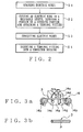
FIG.2 is a flowchart for manufacturing a wiring harness by using the wiring
harness manufacturing apparatus shown in FIG.1.
FIG.3(a) is an explanatory illustration of a painting device attached to a wire
stocking unit of the wiring harness manufacturing apparatus shown in FIG.1.
FIG.3(b) is an explanatory illustration of an electric wire colored by the painting
device of FIG.3(a).
FIG.4(a) is an explanatory illustration of another painting device attached to the
wire stocking unit of the wiring harness manufacturing apparatus shown in FIG.1.
FIG.4(b) is an explanatory illustration of an electric wire colored by the painting
device of FIG.4(a).
FIG.5(a) is an explanatory illustration of still another painting device attached to
the wire stocking unit of the wiring harness manufacturing apparatus shown in
FIG.1. FIG.5(b) is an explanatory illustration of an electric wire colored by the
painting device of FIG.5(a).
FIG.6(a) is an explanatory illustration of a painting device attached to a cutting
unit of the Wiring harness manufacturing apparatus shown in FIG.1. FIG.6(b) is
an explanatory illustration of an electric wire colored by the painting device of
FIG.6(a).
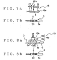
FIG.7(a) is an explanatory illustration of an example of a painting device
attached to a cutting unit and a joining unit of the wiring harness manufacturing
apparatus shown in FIG.1. FIG.7(b) is an explanatory illustration of an electric
wire colored by the painting device of FIG.7(a).
FIG.8(a) is an explanatory illustration of another example of a painting device
attached to a cutting unit and a joining unit of the wiring harness manufacturing
apparatus shown in FIG.1. FIG.8(b) is an explanatory illustration of an electric
wire colored by the painting device of FIG.8(a).
FIG.9 is a block diagram showing wiring harness manufacturing steps, using the
wiring harness manufacturing apparatus shown in FIG.1, and rough appearances
the electric wires.
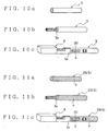
FIG.10(a) is an explanatory illustration showing a first example of an electric
wire to be assembled by using the wiring harness manufacturing apparatus shown
in FIG.1. FIG.10(b) is an explanatory illustration showing the electric wire whose
covering portion has been partly removed. FIG.10(c) is an explanatory illustration
showing the electric wire to which a terminal fitting is attached.
FIG.11(a) is an explanatory illustration showing a second example of an electric
wire to be assembled by using the wiring harness manufacturing apparatus shown
in FIG.1. FIG.11(b) is an explanatory illustration showing the electric wire whose
covering portion has been partly removed. FIG.11(c) is an explanatory illustration
showing the electric wire to which a terminal fitting is attached.
FIG.12(a) is an explanatory illustration showing a third example of an electric
wire to be assembled by using the wiring harness manufacturing apparatus shown
in FIG.1. FIG.12(b) is an explanatory illustration showing the electric wire whose
covering portion has been partly removed. FIG. 12(c) is an explanatory illustration
showing the electric wire to which a terminal fitting is attached. FIG.12(d) is an
explanatory illustration showing the electric wire on which a mark is put and to
which a terminal fitting is attached.
FIG.13(a) is an explanatory illustration showing a fourth example of an electric
wire to be assembled by using the wiring harness manufacturing apparatus shown
in FIG.1. FIG.13(b) is an explanatory illustration showing the electric wire whose
covering portion has been partly removed. FIG. 13(c) is an explanatory illustration
showing the electric wire to which a terminal fitting is attached. FIG.13(d) is an
explanatory illustration showing the electric wire on which a mark is put and to
which a terminal fitting is attached.
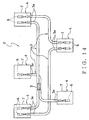
FIG.14 is a schematic illustration showing the structure of the wiring harness
assembled by the wiring harness manufacturing apparatus shown in FIG.I.
FIG.15 is a block diagram showing the structure of a wiring harness
manufacturing apparatus in accordance with the second embodiment of the present
invention.
FIG.16 is a flowchart for manufacturing a wiring harness by using the wiring
harness manufacturing apparatus shown in FIG.15.
FIG.17 is a block diagram showing wiring harness manufacturing steps, using
the wiring harness manufacturing apparatus shown in FIG.15, and rough
appearances the electric wires.
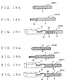
FIG.18(a) is an explanatory illustration showing an example of an electric wire
to be assembled by using the wiring harness manufacturing apparatus shown in
FIG.15. FIG:18(b) is an explanatory illustration showing the electric wire whose
covering portion has been partly removed. FIG.18(c) is an explanatory illustration
showing the electric wire to which a terminal fitting is attached.
FIG.19(a) is an explanatory illustration showing another example of an electric
wire to be assembled by using the wiring harness manufacturing apparatus shown
in FIG.15. FIG.19(b) is an explanatory illustration showing the electric wire
whose covering portion has been partly removed. FIG.19(c) is an explanatory
illustration showing the electric wire to which a terminal fitting is attached.
FIG.19(d) is an explanatory illustration showing the electric wire on which a mark
is put and to which a terminal fitting is attached.
Best Mode of the Invention
The first embodiment of the inventive wiring harness manufacturing method and
wiring harness manufacturing apparatus will now be described in further detail with
reference to FIGS.1 - 14. A wiring harness manufacturing apparatus 1, shown in
FIG.1, in accordance with the first embodiment manufactures or assembles a wiring
harness 2 shown in FIG. 14.
The wiring harness 2 is arranged on a motor vehicle. The wiring harness 2 has
electric wires 3, connectors 4, and joint-terminals 5 as shown in FIG.14. The
electric wire 3 is a covered wire having a conductive core wire and an insulative
covering portion covering the core wire. The electric wires 3 are bundled.
The connector 4 has a conductive terminal fitting 6 and an insulative connector
housing 7. The terminal fitting 6 is formed by bending a conductive sheet metal.
The terminal fitting 6 is attached to an end portion 3a of the electric wire 3. The
terminal fitting 6 is electrically-connected with the core wire of the electric wire 3.
The connector housing 7 is formed in a box-shape. The connector housing 7
accommodates the terminal fitting 6. Like this, the terminal fitting 6 is attached to
the connector housing 7.
The joint-terminal 5 is made of conductive sheet metal. The joint-terminal 5
electrically-connects core wires of the respective electric wires 3. At the
connecting portion of the electric wires 3, the covering portions of the electric
wires 3 are removed, and the core wires are exposed. The joint-terminal 5 covers
the exposed core wires. The joint-terminal 5 crimps the core wires of the electric
wires 3, thereby electrically-connecting the electric wires 3.
In the wiring harness 2 of the above structure, the electric wires 3 have been cut
off in desirable lengthes, and the covering portions of the end portions 3a have been
removed. The terminal fittings 6 are crimped to the core wires exposed from the
end portions 3a. The covering portions of the connecting portion of the electric
wires 3a are removed. The core wires exposed from the connecting portion are
crimped by the joint-terminal 5 so as to connect the electric wires 3. The terminal
fitting 6 is inserted into, and attached to, the connector housing 7.
Like this, the wiring harness 2 of the above structure is assembled. The wiring
harness 2 connects a plurality of electronic equipment mounted on a motor vehicle
by coupling the above connectors 4 with mating connectors of the electronic
equipment. The wiring harness 2 supplies electric power or transmits control
signals to the electronic equipment.
The wiring harness manufacturing apparatus 1 assembles or manufactures the
wiring harness 2 of the above structure. The wiring harness manufacturing
apparatus 1 has wire stocking units 10, cutting units 11, joining units 12 and case
insertion unit 13 as shown in FIG.1. In the embodiment shown in FIG.1, the
wiring harness manufacturing apparatus 1 has a pair of wire stocking units 10, a
pair of cutting units 11 and a pair of joining units 12.
The electric wire 3 is supplied to the wire stocking unit 10 from a wire
manufacturing apparatus 9. The electric wire 3 is, for example, rolled on a real.
The wire manufacturing apparatus 9 makes the above core wire from conductive
metal such as copper. The core wire is covered with insulative synthetic resin by
the wire manufacturing apparatus 9. The covering portion of the electric wire 3
made by the wire manufacturing apparatus 9 is in a non-colored state. That is, a
non-colored electric wire 3 is supplied to the wire stocking unit 10. Here, the non-colored
electric wire 3 has the covering portion of synthetic resin in which colorant
is not put. That is, the covering portion of the non-colored electric wire 3 has a
color of synthetic resin itself.,
In this specification, "to color the outer surface of the electric wire 3" means to
color the outer surface of the covering portion of the electric wire 3 with a colorant.
The colorant is a liquid substance in which color material (organic substance for
industry) is dissolved and dispersed in water or in other solvent. As the organic
substance, there exists dyes and pigments (mostly organic substance and synthetic
material). In the present specification, "colorant" means both paint and coloring
liquid.
In the coloring liquid, the dye is dissolved or dispersed in the solvent. In the
paint, the pigment is dispersed in the dispersion liquid. Therefore, when the outer
surface of the covering portion is colored by the coloring liquid, the dye soaks into
in the covering portion, and when the outer surface of the covering portion is
colored by the paint, the pigment adheres to the outer surface without soaking into
the covering portion. That is, "to color the outer surface of the covering portion of
the electric wire" in the present specification means to dye the outer surface of the
covering portion of the electric wire 3 with the dye and also to paint the pigment on
the outer surface of the covering portion of the electric wire 3.
And, the solvent and the dispersion liquid should have an affinity for synthetic
resin forming the covering portion of the electric wire 3 so that the dye securely
soaks into the covering portion of the electric wire 3 and the pigment securely
adheres to the outer surface of the covering portion of the electric wire 3.
The wire stocking unit 10 once stocks the electric wire 3 supplied from the wire
manufacturing apparatus 9. The painting devices 14,15,16 as the coloring means
are attached to one of the pair of wire stocking units 10 (hereinafter, 10a). The
painting devices 14,15,16 color the outer surface of the above electric wire 3
differently from a color of synthetic resin of the covering portion.
Each of the pair of wire stocking units 10a,10b supplies the electric wires 3 to
the respective cutting units 11. The electric wire 3 supplied to the cutting unit 11
is in a state of being rolled on a reel. The cutting unit 11 cuts off the electric wire
3 in a desirable length. The cutting unit 11 removes the covering portions of the
end portions 3a of the electric wire 3. The cutting unit 11 attaches the terminal
fittings 6 to the respective end portions 3a of the electric wire 3.
At least one of the painting devices 17,18,19 is attached to one cutting unit
(hereinafter, 11 a) of the pair of cutting units 11. In the illustrated embodiment, the
painting devices 17,18,19 are attached to the cutting unit 11a. The painting
devices 17,18,19 color the outer surface of the above electric wire 3 differently
from a color of synthetic resin of the covering portion.
At least one of the painting devices 18,19 as the coloring means is attached to
one joining unit (hereinafter, 12a) of the pair of joining units 12. In the illustrated
embodiment, the painting devices 18,19 are attached to the joining unit 12a. The
painting devices 18,19 color the outer surface of the above electric wire 3
differently from a color of synthetic resin of the covering portion.
The electric wire 3, to which the terminal fittings 6 have been attached by the
other cutting unit 11b, is supplied to the joining unit 12a from the cutting unit 11b.
The electric wire 3, to which the terminal fittings 6 have been attached, is supplied
to the other joining unit 12b from each of the pair of cutting units 11a, 11b. The
joining units 12a, 12b remove the covering portions of the above-described
connecting portions of the electric wires 3 and crimp the core wires with the joint-terminal
5 so as to connect the electric wires 3.
The electric wire 3 with the terminal fitting 6 is supplied to the case insertion
unit 13 from each of the pair of joining units 12a,12b. The case insertion unit 13
inserts the terminal fitting 6 attached to the end portion 3 a of the electric wire 3 into
the connector housing 7, thereby assembling the connector 4.
The painting- device 14 has an apparatus body 14a, a pair of rollers 14b, a
plurality of sprayers 14c and a dryer 14d as shown in FIG.3(a). The pair of rollers
14b are arranged with some interval, and the electric wire 3 is arranged between the
rollers 14b.
A pair of sprayers 14c are provided in the illustrated embodiment. The sprayer
14c sprays the colorant toward the electric wire 3 traveling between the rollers 14b.
The pair of sprayers 14c color the outer surface of the electric wire 3 over the
whole periphery thereof. The sprayers 14c color the outer surface of the electric
wire 3 differently from a color of synthetic resin of the covering portion over the
whole periphery of the electric wire 3.
The drier 14d is arranged downstream of the sprayers 14c in a traveling direction
of the electric wire 3. The drier 14d dries the colorant blown on the outer surface
of the electric wire 3 by the sprayers 14c. The painting device 14 of the above
structure colors the outer surface of the electric wire 3 in a color P (a hatched
portion in FIG.3(b)) different from a color of synthetic resin of the covering portion
over the whole periphery of the electric wire 3.
The painting device 15 has a pair of rollers 15a, sprayers 15b and markers 15c as
shown in FIG.4(a). The pair of rollers 15a are arranged with some interval, and
the electric wire 3 is arranged between the rollers 15a.
A pair of sprayers 15b are provided in the illustrated embodiment. The sprayer
15b sprays the colorant toward the electric wire 3 traveling between the rollers 15a.
The sprayers 15b color the outer surface of the electric wire 3. The sprayers 15b
color the outer surface of the electric wire 3 differently from a color of synthetic
resin of the covering portion over the whole periphery of the electric wire 3.
A pair of markers 15c are provided in the illustrated embodiment. The markers
15c are arranged downstream of the sprayers 15b in a traveling direction of the
electric wire 3. The marker 15c puts the colorant partly on the outer surface of the
electric wire 3, which colorant has a color different from both the color colored by
the sprayer 15b and the color of the covering portion.
In the painting device 15 of the above structure, the sprayer 15b colors the outer
surface of the electric wire 3 in a color P (a hatched portion in FIG.4(b)) different
from a color of synthetic resin of the covering portion over the whole periphery of
the electric wire 3. And then, the marker 15c colors the outer surface, having
been colored by the sprayer 15b, in a color R different from the color P and the
color of the covering portion itself. The painting device 15 colors the outer
surface of the electric wire 3 in a pattern of stripe of the colors P,R as shown in
FIG.4(b).
The painting device 16 has a pair of rollers 16a and a plurality of markers 16b as
shown in FIG.5(a). The pair of rollers 16a are arranged with some interval, and
the electric wire 3 is arranged between the rollers 16a.
A pair of markers 16b are provided in the illustrated embodiment. The marker
16b partly put a colorant on the outer surface of the electric wire 3. The pair of
markers 16b partly color the outer surface of the electric wire 3 differently from a
color of synthetic resin of the covering portion.
In the painting device 16 of the above structure, the marker 16b partly colors the
outer surface of the electric wire 3 in a color R (a hatched portion in FIG.5(b))
different from a color of synthetic resin of the covering portion. The painting
device 16 colors the outer surface of the electric wire 3 in a pattern of stripe of the
color R as shown in FIG.5(b).
The painting device 17 has a pair of running rollers 17a, a tubular member 17b
and a coloring unit 17c as shown in FIG.6(a). The pair of running rollers 17a put
the electric wire 3 therebetween and make the electric wire 3 run.
The tubular member 17b is formed tubularly in order to receive the end portion
3a of the electric wire 3. The tubular member 17b is provided with a through-hole
17d. The coloring unit 17c partly puts a colorant on the outer surface of the
electric wire 3 in the tubular member 17b through the through-hole 17d. The
coloring unit 17c partly colors the outer surface of the electric wire 3 differently
from a color of synthetic resin of the covering portion (that is, marking is carried
out on the end portion).
In the painting device 17 of the above structure, the coloring unit 17c partly
colors the outer surface of the electric wire 3 in a color S (a hatched portion in
FIG.6(b)) different from the colors P,R. The painting device 17 partly colors the
outer surface of the electric wire 3 in the color S so as to form a mark 20 as shown
in FIG.6(b).
The painting device 18 has wire clampers 18a and sprayers 18b as shown in
FIG.7(a). The wire clamper 18a clamps the end portion 3a of the electric wire 3.
The sprayer 18b partly sprays a colorant on the outer surface of the end portion 3a
of the electric wire 3. The sprayer 18b partly colors the outer surface of the
electric wire 3 differently from a color of synthetic resin of the covering portion
(that is, marking is carried out on the end portion).
In the painting device 18 of the above structure, the sprayer 18b partly colors the
outer surface of the electric wire 3 in a color S (a hatched portion in FIG.7(b))
different from the colors P,R. The painting device 18 partly colors the outer
surface of the electric wire 3 in the color S so as to form a mark 20 as shown in
FIG.7(b).
The painting device 19 has wire clampers 19a and a stamper 19b as shown in
FIG.8(a). The wire clamper 19a has holding members 19c,19c which close and
open each other. The wire clamper 19a sandwiches the end portion 3a of the
electric wire 3 between the holding members 19c,19c.
The stamper 19b moves relative to the end portion 3a of the electric wire 3 along
with the holding members 19c,19c. That is, the stamper 19b approaches the end
portion 3a of the electric wire 3 when the holding members 19c,19c close each
other. The stamper 19b is put into contact with the end portion 3a and partly puts
a colorant on the outer surface of the end portion 3a. The stamper 19b partly
colors the outer surface of the electric wire 3 differently from a color of synthetic
resin of the covering portion (that is, marking is carried out on the end portion).
In the painting device 19 of the above structure, the stamper 19b partly colors the
outer surface of the electric wire 3 in a color S (a hatched portion in FIG.8(b))
different from the colors P,R The painting device 19 partly colors the outer
surface of the electric wire 3 in the color S so as to form a mark 20 as shown in
FIG.8(b).
When the wiring harness 2 is manufactured by using the above wiring harness
manufacturing apparatus 1, the electric wire 3 wound up on a reel is firstly stocked
once in each of the wire stocking units 10a, 10b at Step S1 as a wire stocking step in
FIG.2 and FIG.9.
The wire stocking unit 10a colors the outer surface of the electric wire 3 over the
whole periphery thereof by using the painting device 14, forms (colors) a stripe
pattern on the outer surface of the electric wire 3 by using the painting device 15, or
forms (colors) a stripe pattern on the outer surface of the electric wire 3 by using
the painting device 16. And then, Step S2 (shown in FIG.2 and FIG.9) as a
cutting step is reached.
In Step S2, the electric wires 3 are conveyed toward the cutting units 11a, 11b
from the wire stocking units 10a,10b. The cutting units 11a, 11b cut off the
electric wires 3 in desirable lengthes, remove the covering portions of the end
portions 3a, and attach the terminal fittings 6 to the end portions 3a.
The cutting unit 11a forms the mark 20 on the end portion 3a of the electric wire
3 by using one of the painting devices 17,18,19 (that is, marking is carried out on
the end portion). And then, Step S3 (shown in FIG.2 and FIG.9) as a joining step
is reached.
In Step S3, the electric wire 3 is conveyed toward the joining unit 12b from the
cutting unit 11a, and the electric wires 3 are conveyed toward the joining units
12a, 12b from the cutting unit 11b. The joining units 12a,12b remove the covering
portions of the connecting portions of the electric wires 3 and connect the electric
wires 3 with the joint-terminal 5.
The joining unit 12a forms the mark 20 on the end portion 3a of the electric wire
3 by using one of the painting devices 18,19 (that is, marking is carried out on the
end portion). And then, Step S4 (shown in FIG.2 and FIG.9) as a case insertion
step is reached.
In Step S4, the electric wires 3 are conveyed toward the case insertion unit 13
from the joining units 12a,12b. The case insertion unit 13 inserts the terminal
fitting 6 attached to the end portion 3a of the electric wire 3 into the connector
housing 7. Like this, the wiring harness manufacturing apparatus 1 assembles the
wiring harness 2.
As above, when the non-colored electric wire 3 shown in FIG.10(a) is supplied
to the wire stocking unit 10b, the covering portion of the end portion 3 a is removed
as shown in FIG.10(b) at the cutting step. Subsequently, the above mark 20 is
formed in either the cutting step or the joining steps, that is, in either the cutting
unit 11a or the joining unit 12a. As shown in FIG.10(c), the electric wire 3 with
the terminal fitting 6 at the end portion 3a thereof is obtained.
Upon the supply of the non-colored electric wire 3 to the wire stocking unit 10a,
the electric wire 3 is colored by using the painting device 14. Then, as shown in
FIG.11(a), the electric wire 3 (hereinafter, 23) colored in the color P over the whole
periphery thereof is obtained. The covering portion of the end portion 3a is
removed at the cutting step as shown in FIG.11(b). Subsequently, the above mark
20 is formed in either the cutting step or the joining steps, that is, in either the
cutting unit 11a or the joining unit 12a. As shown in FIG.11(c), the electric wire 3
with the terminal fitting 6 at the end portion 3a thereof is obtained.
Upon the supply of the non-colored electric wire 3 to the wire stocking unit 10a,
the electric wire 3 is colored by using the painting device 15. Then, as shown in
FIG. 12(a), the electric wire 3 (hereinafter, 33) with a stripe pattern in the colors P,R
is obtained. The covering portion of the end portion 3a is removed at the cutting
step as shown in FIG.12(b).
Subsequently, the above mark 20 is formed in either the cutting step or the
joining steps, that is, in either the cutting unit 11a or the joining unit 12a. As
shown in FTG.12(d), the electric wire 3 with the terminal fitting 6 at the end portion
3a thereof is obtained. On the other hand, the electric wire 33 shown in FIG.12(b)
is conveyed to the cutting unit 11b and the joining unit 12b. And then, the electric
wire 33 with the terminal fitting 6 at the end portion 3 a thereof but without a mark
is obtained as shown in FIG.12(c).
Upon the supply of the non-colored electric wire 3 to the wire stocking unit 10a,
the electric wire 3 is colored by using the painting device 16. Then, as shown in
FIG.13(a), the electric wire 3 (hereinafter, 43) with a stripe pattern in the color R is
obtained. The covering portion of the end portion 3a is removed at the cutting
step as shown in FIG. 13(b).
Subsequently, the above mark 20 is formed in either the cutting step or the
joining steps, that is, in either the cutting unit 11a or the joining unit 12a. As
shown in FIG.13(d), the electric wire 3 with the terminal fitting 6 at the end portion
3a thereof is obtained. On the other hand, the electric wire 43 shown in FIG.13(b)
is conveyed to the cutting unit 11b and the joining unit 12b. And then, the electric
wire 43 with the terminal fitting 6 at the end portion 3a thereof but without a mark
is obtained as shown in FIG. 13(c).
According to the present embodiment, as shown in FIG.9, the outer surface of
the electric wire 3 is colored in one of the wire stocking step and the cutting step.
And, as shown in FIG.9, the outer surface of the electric wire 3 is colored in one of
the wire stocking step, the cutting step and the joining step. Further, the outer
surface of the electric wire 3 is colored in one of the cutting step and the joining
step. Like this, the electric wire 3 is not necessarily colored in all the steps.
Therefore, the painting devices 14,15,16,17,18,19 to color the electric wire 3 need
not to be provided on all the wire stocking units 10a, 10b, the cutting units 11a, 11b,
and the joining units 12a,12b. Therefore, the number of the painting devices
14,15,16,17,18,19 can be reduced, and the space for the wiring harness
manufacturing apparatus 1 can be reduced.
And, because the electric wire 3 is not necessarily colored in all the steps, all the
electric wires 3 need not to be conveyed to the painting devices 14,15,16,17,18,19
from the wire stocking units 10a,10b, the cutting units 11a,11b, and the joining
units 12a,12b. Therefore, the conveying work of the electric wires 3 can be
reduced, and production efficiency for manufacturing the wiring harness 2 can be
improved, thereby reducing the production cost of the wiring harness 2.
Further, the electric wire 3 is colored in a step for assembling the wiring harness
2. Therefore, the article number (the kind of color of the outer surface) of the
electric wire 3 stocked by the wire stocking units 10a, 10b can be reduced.
Therefore, trouble of controlling the electric wire 3 can be reduced, which could
prevent the article number from being mistaken during the assembly of the wiring
harness 2. Therefore, the yield of the wiring harness 2 can be improved.
The painting devices 14,15,16,17,18,19 to color the electric wire 3 are attached
only to the wire stocking unit 10a, the cutting unit 11a, and the joining unit 12a.
Like this, the painting devices 14,15,16,17,18,19 to color the electric wire 3 need
not to be provided on all the wire stocking units 10a,10b, the cutting units 11a, 11b,
and the joining units 12a,12b. Therefore, the number of the painting devices
14,15,16,17,18,19 can be reduced, and the space for the wiring harness
manufacturing apparatus 1 can be reduced, thereby reducing the production cost of
the wiring harness 2.
Next, the second embodiment of the inventive wiring harness manufacturing
method and wiring harness manufacturing apparatus will now be described in
further detail with reference to FIGS.15 - 19. Here, the same references are
assigned to the same elements or members as the above first embodiment, and the
description thereof is omitted.
An electric wire 23 colored in a color P over the whole periphery is supplied
from a wire manufacturing apparatus 9 to a wiring harness manufacturing apparatus
1 of the present embodiment. A painting device 16 is attached to a wire stocking
unit 10a.
A wiring harness 2 is assembled through Step S1 to Step S4 shown in FIG. 16
and FIG.17 by using the wiring harness manufacturing apparatus 1, similarly to the
above-described first embodiment.
The electric wire 23 having been colored as shown in FIG.18(a) is supplied to a
wire stocking unit 10b. Then, a covering portion of an end portion 3a is removed
as shown in FIG.18(b) in the cutting step. Subsequently, the above mark 20 is
formed in either the cutting step or the joining steps, that is, in either the cutting
unit 11a or the joining unit 12a (that is, marking is carried out on the end portion).
As shown in FIG.18(c), the electric wire 23 with a terminal fitting 6 at the end
portion 3a thereof is obtained.
Upon the supply of the colored electric wire 23 to the wire stocking unit 10a, the
electric wire 23 is colored by using the painting device 16. Then, as shown in
FIG.19(a), the electric wire 33 with a stripe pattern in the colors P,R is obtained.
The covering portion of the end portion 3a is removed at the cutting step as shown
in FIG.19(b).
Subsequently, the above mark 20 is formed in either the cutting step or the
joining steps, that is, in either the cutting unit 11a or the joining unit 12a (that is,
marking is carried out on the end portion). As shown in FIG.19(d), the electric
wire 3 with the terminal fitting 6 at the end portion 3 a thereof is obtained. On the
other hand, the electric wire 33 shown in FIG.19(b) is conveyed to the cutting unit
11b and the joining unit 12b. And then, the electric wire 33 with the terminal
fitting 6 at the end portion 3a thereof but without a mark is obtained as shown in
FIG.19(c).
According to the present embodiment, similarly to the above-described first
embodiment, the painting devices 16,17,18,19 to color the electric wire 3 are
attached only to the wire stocking unit 10a, the cutting unit 11a, and the joining unit
12a. Like this, the painting devices 16,17,18,19 to color the electric wire 3 need
not to be provided on all the wire stocking units 10a,10b, the cutting units 11a, 11b,
and the joining units 12a,12b. Therefore, the number of the painting devices
16,17,18,19 can be reduced, and the space for the wiring harness manufacturing
apparatus 1 can be reduced, thereby reducing the production cost of the wiring
harness 2.
Here, the color and the marking of the electric wires 3,23,33,43 are not used for
indicating the steps for assembling the wiring harness 2 as shown in FIG.10 -
FIG.13,FIG.18,FIG,19. The color and the marking of the electric wires
3,23,33,43 ware used for indicating the kind of electric wire and the electric or
electronic system in which the wiring harness 2 is used.
Various electric wires 3,23,33,43 shown in FIG.10 - FIG.13,FIG.18,FIG,19 can
be made by using the above-described wiring harness manufacturing apparatus 1.
Further, in the present invention, the coloring of the electric wire 3 by the painting
devices 14,15,16,17,18,19 can be carried out at any step of cutting the electric wire
3, removing the covering portion, attaching the terminal fitting 6, and inserting the
terminal fitting 6. Preferably, the coloring of the electric wire 3 by the painting
devices 14,15,16,17,18,19 is carried out just after any of the above steps.
Here, in the above first and second embodiments of the wiring harness
manufacturing apparatus 1, the mark 20 is formed on the electric wires 3,23 in
either the cutting step or the joining step. However, in the present invention, the
mark 20 may not be formed on the electric wires 3,23 in both the cutting step and
the joining step.
Further, in the above-described embodiment, the units 10a, 11a, 12a are provided
with some of the painting devices 14,15,16,17,18,19. However, the painting
devices 14,15,16,17,18,19 may be provided on any one (one portion) of the units
10a, 10b, 11a, 11b, 12a, 12b. That is, the painting devices 14,15,16,17,18,19 may be
provided on at least one of the wire stocking unit 10a and the cutting unit 11a.
The painting devices 14,15,16,17,18,19 may be provided on at least one of the wire
stocking unit 10a, the cutting unit 11a, and the joining unit 12a.
Industrial Applicability
As described above, in the present invention set forth in claim 1, the electric wire
is colored in at least one of the wire stocking step and the cutting step. Like this,
since the electric wire is not necessarily colored in all the steps, the device to color
the electric wire needs not to be attached to all the units to carry out the wire
stocking step and the cutting step. Therefore, the number of the device to color
the electric wire can be reduced, and a space for the apparatus for carrying put the
wiring harness manufacturing method can be reduced.
And, because the electric wire is not necessarily colored in all the steps, all the
electric wires need not to be conveyed to the devices to color the electric wire from
the units to carry out the wire stocking step and the cutting step. Therefore, the
conveying work of the electric wires can be reduced, and production efficiency for
manufacturing the wiring harness can be improved, thereby reducing the
production cost of the wiring harness.
Further, the electric wire is colored in a step for assembling the wiring harness.
Therefore, the article number (the kind of color of the outer surface) of the electric
wire stocked by the wire stocking units can be reduced. Therefore, trouble of
controlling the electric wire can be reduced, which could prevent the article number
from being mistaken during the assembly of the wiring harness. Therefore, the
yield of the wiring harness can be improved.
In the present invention set forth in claim 2, the electric wire is colored in at least
one of the wire cutting step and the joining step. Like this, since the electric wire
is not necessarily colored in all the steps, the device to color the electric wire needs
not to be attached to all the units to carry out the wire cutting step and the joining
step. Therefore, the number of the device to color the electric wire can be reduced,
and a space for the apparatus for carrying put the wiring harness manufacturing
method can be reduced.
And, because the electric wire is not necessarily colored in all the steps, all the
electric wires need not to be conveyed to the devices to color the electric wire from
the units to carry out the wire stocking step, the cutting step, and the joining step.
Therefore, the conveying work of the electric wires can be reduced, and production
efficiency for manufacturing the wiring harness can be improved, thereby reducing
the production cost of the wiring harness.
Further, the electric wire is colored in a step for assembling the wiring harness.
Therefore, the article number (the kind of color of the outer surface) of the electric
wire stocked by the wire stocking units can be reduced. Therefore, trouble of
controlling the electric wire can be reduced; which could prevent the article number
from being mistaken during the assembly of the wiring harness. Therefore, the
yield of the wiring harness can be improved.
In the present invention set forth in claim 3, the coloring means to color the
electric wire are attached to one of the wire stocking units and the cutting units.
Like this, the coloring means- need not to be provided on all the wire stocking units
and the cutting units. Therefore, the number of the coloring means can be reduced,
and the space for the wiring harness manufacturing apparatus can be reduced,
thereby reducing the production cost of the wiring harness.
And, the electric wire is colored by the coloring means in a step for assembling
the wiring harness. Therefore, the article number (the kind of color of the outer
surface) of the electric wire stocked by the wire stocking units can be reduced.
Therefore, trouble of controlling the electric wire can be reduced, which could
prevent the article number from being mistaken during the assembly of the wiring
harness. Therefore, the yield of the wiring harness can be improved.
In the present invention set forth in claim 4, the coloring means to color the
electric wire are attached to one of the wire stocking units, the cutting units, and the
joining units. Like this, the coloring means need not to be provided on all the
wire stocking units, the cutting units, and the joining units. Therefore, the number
of the coloring means can be reduced; and the space for the wiring harness
manufacturing apparatus can be reduced, thereby reducing the production cost of
the wiring harness.
And, the electric wire is colored by the coloring means in a step for assembling
the wiring harness. Therefore, the article number (the kind of color of the outer
surface) of the electric wire stocked by the wire stocking units can be reduced.
Therefore, trouble of controlling the electric wire can be reduced, which could
prevent the article number from being mistaken during the assembly of the wiring
harness. Therefore, the yield of the wiring harness can be improved.