EP1431925A2 - Transportmechanismuns für eine Postmaschine und Verfahren zum Registrieren einer Postsendung in einer Postmaschine - Google Patents
Transportmechanismuns für eine Postmaschine und Verfahren zum Registrieren einer Postsendung in einer Postmaschine Download PDFInfo
- Publication number
- EP1431925A2 EP1431925A2 EP03029209A EP03029209A EP1431925A2 EP 1431925 A2 EP1431925 A2 EP 1431925A2 EP 03029209 A EP03029209 A EP 03029209A EP 03029209 A EP03029209 A EP 03029209A EP 1431925 A2 EP1431925 A2 EP 1431925A2
- Authority
- EP
- European Patent Office
- Prior art keywords
- roller
- mail piece
- belt
- rollers
- idler roller
- Prior art date
- Legal status (The legal status is an assumption and is not a legal conclusion. Google has not performed a legal analysis and makes no representation as to the accuracy of the status listed.)
- Granted
Links
Images

Classifications
-
- G—PHYSICS
- G07—CHECKING-DEVICES
- G07B—TICKET-ISSUING APPARATUS; FARE-REGISTERING APPARATUS; FRANKING APPARATUS
- G07B17/00—Franking apparatus
- G07B17/00459—Details relating to mailpieces in a franking system
- G07B17/00467—Transporting mailpieces
Definitions
- the invention disclosed herein relates generally to mailing systems, and more particularly to a mailing machine transport mechanism and method.
- Mailing systems such as, for example, a mailing machine, often include different modules that automate the processes of producing mail pieces.
- the typical mailing machine includes a variety of different modules or sub-systems each of which performs a different task on the mail piece.
- the mail piece is conveyed downstream utilizing a transport mechanism, such as rollers or a belt, to each of the modules.
- Such modules could include, for example, a singulating module, i.e., separating a stack of mail pieces such that the mail pieces are conveyed one at a time along the transport path, a moistening/sealing module, i.e., wetting and closing the glued flap of an envelope, a weighing module, and a metering/printing module, i.e., applying evidence of postage to the mail piece.
- a singulating module i.e., separating a stack of mail pieces such that the mail pieces are conveyed one at a time along the transport path
- a moistening/sealing module i.e., wetting and closing the glued flap of an envelope
- a weighing module e., weighing module
- a metering/printing module i.e., applying evidence of postage to the mail piece.
- the exact configuration of the mailing machine is, of course, particular to the needs of the user.
- Modern mailing machines utilize digital printing techniques for producing images on a mail piece being processed therethrough.
- Conventional digital printing techniques include bubble jet and ink jet, each of which produces an image in a dot matrix pattern.
- individual print head elements such as resistors or piezoelectric elements
- a dot matrix pattern is produced in the visual form of the desired indicia, i.e., the evidence of postage.
- Digital printing technology has significant advantages when used in a mail handling apparatus as compared to older technology that utilized either a flat platen or a rotary drum to imprint indicia on mail pieces. For example, if the variable indicia image data needs to be changed, it can easily be done through the installation of new or upgraded software versus having to replace the entire meter, since the flat platen and drum are typically not separately removable. Moreover, greater printing speeds can be obtained as compared to conventional mechanical printing systems. However, the use of a digital print head in a mail handling apparatus presents other issues that must be taken into consideration.
- the ink jet nozzles of an ink jet printer to properly deposit ink on the surface of the receiving medium, it is critical that a small predetermined gap be maintained between the exit plane of the nozzles and the surface of the receiving medium, typically in the order of one sixteenth to one thirty-second of an inch.
- This gap is necessary to achieve acceptable image quality, since too small a gap causes scuffing of the print head and to large a gap results in inaccurate dot placement, with either situation resulting in a deteriorated print image.
- the mail pieces such as, for example, envelopes, postcards, flats, and the like
- the front panels on which the postage indicia is printed lying in a fixed registration plane, which is disposed beneath the exit plane of the nozzles a distance equal to the aforementioned gap.
- This arrangement is referred to hereinafter as top registration.
- top registration The problem that arises, however, with top registration is that the plane of the rear panel of the mail piece is not fixed, as is the case with bottom registration, but rather must shift vertically in accordance with variations in the thickness of the mail pieces being conveyed through the mailing machine.
- the mailing machine must be capable of accepting mail pieces of varying thickness.
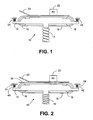
- Figs. 1 and 2 illustrate a portion of a conventional mailing machine, including a transport mechanism 10, that provides top registration of a mail piece.
- Transport 10 includes a support bracket 12 coupled to a support spring 14.
- One or more drive/idler rollers 16 are mounted to the support bracket 12.
- a belt 18 is looped around the drive/idler rollers 16.
- At least one drive roller 16 is coupled to a motor (not shown) that controls rotation of the drive roller 16, and hence movement of the belt 18.
- a registration plate 20 is situated above the belt 18.
- a print head 22 is mounted adjacent to the registration plate 20, situated over an opening (not shown) in the registration plate 20.
- Spring 14 maintains a biasing force on support bracket 12, and hence the belt 18, in the direction of the registration plate 20.
- the mail piece 30 As a mail piece 30 is transported by the movement of the belt 18 in the gap between the belt 18 and the bottom surface of the registration plate 20, the mail piece 30 is kept registered against the bottom surface of registration plate 20 by the force exerted from spring 14, thereby fixing the distance between the print head 22 and the top surface of the mail piece 30.
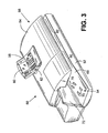
- Most mailing machines are typically designed to handle mail pieces of different thickness, such as, for example, from card stock up to three-quarters of an inch thick. As such, the transport 10 must be displaceable to accommodate the thicker mail pieces. As a thicker mail piece is transported by the transport 10, the spring 14 will compress (as illustrated in Fig. 2), thereby allowing the mail piece to pass between the belt 18 and the registration plate 20, while still maintaining the registration of the mail piece against the bottom surface of the registration plate 20. Compression of the spring 14 will cause a small gap 40 between the support bracket 12 and the up-stops 24.
- the transport 10 including the support bracket 12 and drive/idler rollers 16, is relatively large and heavy.
- the spring 14 must be strong enough to lift both the transport 10, along with a heavy mail piece, to ensure proper registration of the mail piece along the bottom surface of the registration plate 20. This makes it extremely difficult to provide fine adjustments to the gap. If the belt 18 make contact with the registration plate 20, the amount of friction between the two, caused by the force of spring 14, could damage the motor driving the belt 18 or even prevent the belt 18 from moving at all. It is thus necessary to always maintain the small gap between the belt 18 and registration plate 20 to prevent such damage to the motor or immobilization of the belt 18.
- the spring 14 will decompress until the support bracket 12 contacts the up-stops 24.
- this decompression and resulting movement of the support bracket 12 is both quick and forceful, causing a severe shock on the up-stops 24 and transport 10 when the support bracket 12 makes contact.
- the amount of displacement of the transport 10, and corresponding shock to the up-stops 24 and transport 10 upon return to its original position, increases as the mail piece thickness increases.
- the sudden decompression of spring 14 causes several problems. First, the noise associated with the support bracket 12 making contact with the up-stops 24 is substantial.
- This necessary maintenance increases the cost of owning a mailing machine, as well as increases the down time, i.e., time which the machine cannot be used. If the maintenance is not performed regularly to properly maintain the gap, the transport 10 may become inoperable if the gap has decreased (due to the unacceptable amount of friction between the belt 18 and registration plate 20), or may not properly register thin mail pieces, such as card stock, if the gap has increased. Either of these situations will result in dissatisfaction with the mailing machine.
- the present invention alleviates the problems associated with the prior art and provides a transport mechanism and method that provides top registration for mail pieces that can effectively handle mail pieces of different thickness.
- the present invention effectively eliminates the criticality of maintaining the small gap between the belt and registration plate, reduces the occurrence of the spring compressing, and, should the spring compress, reduces the amount of noise and shock associated with the subsequent decompression of the spring.
- a top registration transport mechanism includes one or more additional rollers that are coupled to the drive/idler rollers for the transport belt by pivotable links.
- a semi-elastic belt is looped around the drive/idler rollers and additional rollers.
- the transport mechanism includes a support bracket that is coupled to a spring, which maintains a biasing force on the support bracket in the direction of a registration plate. The amount of movement of the support bracket is limited by one or more up-stops, which preferably are provided with a damping material.
- the additional rollers have a diameter that is larger than the drive/idler rollers, causing a portion of the transport belt in the area of the additional rollers to be slightly raised.
- the registration plate above the transport can contact the raised portion of the belt to displace the belt and additional rollers, thereby ensuring that very thin mail pieces, such as, for example, card stock, can be effectively processed by the transport. Because the mass of the displaced components is very small as compared with the mass of the entire transport, the amount of friction between the belt and registration plate, when no mail piece is present, is limited to an acceptable value. As a mail piece traverses the transport, the additional rollers are further displaced, and registration of the mail piece against the bottom of the registration plate is maintained by the force of the belt acting to return the additional rollers to their original position.
- the force will displace the support bracket and compress the spring.
- the damping material that is provided on the up-stops reduces the shock and noise associated with the support bracket contacting the up-stops.
- the criticality of maintaining the small gap between the belt and registration plate is significantly decreased, as the amount of friction between the belt and registration plate is limited to an acceptable value. Additionally, the compression of the spring supporting the entire transport mechanism will not occur unless the mail piece is a thick mail piece, i.e., the thickness of the mail piece is greater than the difference between the diameter of the additional rollers and the drive/idler rollers. Thus, a large portion of mail pieces can be handled by the transport of the present invention without having to displace the support bracket by compressing the spring. This results in less wear on the transport due to the decrease in shock to the support bracket, up-stops and surrounding components, since the number of times the spring will be compressed and subsequently decompress will be significantly reduced.
- the up-stops can be provided with a damping material. Accordingly, even when the support bracket is displaced by compression of the spring due to a thick mail piece, when the mail piece exits the transport and the spring decompresses, the resulting noise and shock can be significantly reduced.
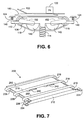
- Mailing machine 50 comprises a base unit, designated generally by the reference numeral 52, the base unit 52 having a mail piece input end, designated generally by the reference numeral 54 and a mail piece output end, designated generally by the reference numeral 56.
- a control unit 58 is mounted on the base unit 52, and includes one or more input/output devices, such as, for example, a keyboard 60 and a display device 62.
- One or more cover members 64 are pivotally mounted on the base 52 so as to move from the closed position shown in Fig. 3 to an open position (not shown) so as to expose various operating components and parts for service and/or repair as needed.
- the base unit 52 further includes a horizontal feed deck 68 which extends substantially from the input end 54 to the output end 56.
- a plurality of nudger rollers 70 are suitably mounted under the feed deck 68 and project upwardly through openings in the feed deck so that the periphery of the rollers 70 is slightly above the upper surface of the feed deck 68 and can exert a forward feeding force on a succession of mail pieces placed in the input end 54.
- a vertical wall 72 defines a mail piece stacking location from which the mail pieces are fed by the nudger rollers 70 along the feed deck 68.
- the mail pieces may be passed through one or more modules, such as, for example, a singulator module (not shown) and moistening/sealing module. Each of these modules is located generally in the area indicated by reference numeral 80.
- the mail pieces are then passed to a metering/printing module located generally in the area indicated by reference numeral 82.
- Transport mechanism 100 could be used, for example to transport a mail piece through the metering/printing module of mailing machine 50.
- Transport mechanism 100 provides top registration of a mail piece and passes the mail piece past a print head 122 for printing thereon.
- Transport 100 includes a support bracket 112 coupled to a support spring 114.
- a drive roller 116 is mounted near a first end of the support bracket 112.
- Drive roller 116 is coupled to a motor (not shown) that controls rotation of the drive roller 116.
- An idler roller 136 is mounted to the support bracket 112 near the end opposite drive roller 116.
- the rollers 116, 136 are fixedly mounted to the support bracket, i.e., they rotate about a fixed shaft.
- a pair of displaceable idler rollers 140, 142 are provided between the drive roller 116 and idler roller 136.
- the shaft of idler roller 140 is coupled to the shaft of idler roller 136 via pivotable link 150
- the shaft of idler roller 142 is coupled to the shaft of drive roller 146 via pivotable link 152.
- the idler rollers 140, 142 could be pivotally mounted directly to the support bracket 112 or mounted in a vertical channel in the support bracket 112.
- rollers 140, 142 can rotate or move vertically, i.e., the shaft of rollers 140, 142 is not fixed and can move with respect to the support bracket 112.
- Rollers 140, 142 preferably have a diameter that is greater than the diameter of rollers 116, 136, and protrude through slots in the top of the support bracket 112.
- the portion of the belt 118 located between the rollers 140, 142 will be raised slightly higher, due to the difference in diameter of rollers 140, 142 and rollers 116, 136, than the portion of the belt 118 nearest the rollers 116, 136.
- Rollers 140, 142 are preferably formed from plastic or other lightweight material.
- a belt 118 is looped around the rollers 116, 136, 140, 142.
- Belt 118 is preferably a semi-elastic belt, and therefore will act to maintain the center of the rollers 136, 116, 140 and 142 parallel to each other in the same plane (not shown), referred to herein as the rest position.
- a registration plate 120 is situated above the belt 118.
- a print head 122 is mounted adjacent to the registration plate 120, situated over an opening (not shown) in the registration plate 120.
- Spring 114 maintains a biasing force on support bracket 112, and hence the belt 118, in the direction of the registration plate 120.
- up-stops 124 are adjustable and are provided with a damping material, such as, for example, rubber.
- the gap between the belt and registration plate is critical, as it must be small enough to run card stock yet large enough to prevent excessive friction between the belt and the registration plate.
- the transport 100 of the present invention effectively eliminates any gap between the belt 118 and registration plate 120 while limiting any frictional drag between the belt 118 and registration plate 120 to a minimal acceptable amount. This is accomplished by the operation of the floating rollers 140, 142 in conjunction with the belt 118. As illustrated in Fig. 4, the home position, i.e., no mail piece present, of support bracket 112 can be set utilizing up-stops 124 such that the pivotable links 150, 152 are slightly off horizontal.
- pivotable links 150, 152 The position of pivotable links 150, 152 is due to the belt 118 making contact with the registration plate 120, thereby providing a downward force on the rollers 140, 142 and displacing the rollers 140, 142, causing the rollers 140, 142 to pivot slightly via links 150, 152.
- the centers of the rollers 140, 142 are slightly lower than the centers of the rollers 116, 136 due to the displacement of the rollers 140, 142.
- the belt 118 will contact the bottom surface of the registration plate 120.
- the mass of the displaced components i.e., rollers 140, 142, links 150, 152 and belt 118
- the amount of friction between the belt 118 and registration plate 120 is limited to an acceptable value, i.e., the amount of frictional torque on the motor (not shown) that is driving the drive roller 116 is such that it will not have any detrimental effects on the motor.
- a "thin" mail piece 130 being transported by the transport 100 of the present invention.
- a "thin” mail piece is defined as a mail piece that has a thickness that is approximately equal to or less than the difference between the diameter of the rollers 140, 142 and rollers 116, 136.
- the mail piece 130 will exert a downward force on the belt 118, thereby causing the rollers 140, 142 to pivot downward via pivoting links 150, 152.
- Mail piece 130 will maintain registration against the bottom surface of registration plate 120 due to the force of belt 118 acting to return the rollers 140, 142 to the rest position.
- the rollers 140, 142 will return to the home position as illustrated in Fig. 4, due top the semi-elasticity of belt 118, to await the next mail piece.
- Mail piece 160 is a "thick" mail piece, i.e., the thickness of mail piece 160 is greater than the difference between the diameter of the rollers 140, 142 and rollers 116, 136.
- the mail piece 160 will exert a downward force on the belt 118, thereby causing the rollers 140, 142 to pivot downward via pivoting links 150, 152.
- any additional force exerted by the mail piece 160 will cause the bottom of the belt 118 to contact the top of the support bracket 112.
- the force of the belt 118 contacting the support bracket 112 will cause the spring 114 to compress.
- the compression of the spring 114 allows the mail piece 160 to pass between the belt 118 and the registration plate 120, while still maintaining the registration of the mail piece 160 against the bottom surface of the registration plate 120. Compression of the spring 114 will cause a small gap 140 between the support bracket 112 and the up-stops 124.
- Mail piece 160 will maintain proper registration against the bottom surface of registration plate 120 due to the force exerted by the compressed spring 114.
- the spring 114 will decompress until the support bracket 112 contacts the up-stops 124 and the rollers 140, 142 will return to the home position (due to the force from belt 118) to await the next mail piece.
- the damping material on up-stops 124 will absorb some of the contact force of the support bracket 112, thereby reducing the shock and noise when the support bracket 112 contacts the up-stops 124.
- the transport 100 has several advantages over conventional transports, such as transport 10 illustrated in Figs. 1 and 2.
- the criticality of maintaining the small gap between the belt 118 and registration plate 120 is significantly decreased.
- the amount of friction between the belt 118 and registration plate 120 is limited to an acceptable value, i.e., the amount of frictional torque on the motor (not shown) that is driving the drive roller 116 is such that it will not have any detrimental effects on the motor.
- the gap spacing between the belt 118 and registration plate 120 is not as critical, and must be maintained only to a point such that the belt 118 is not being pressed against the registration plate 120 by the force of spring 114.
- the compression of spring 114 will not occur unless the mail piece is a thick mail piece, i.e., the thickness of mail piece 160 is greater than the difference between the diameter of the rollers 140, 142 and rollers 116, 136.
- the transport 100 without having to displace the support bracket 112 by compressing the spring 114.
- This results in less wear on the transport 100 due to the decrease in shock to the support bracket 112, up-stops 124 and surrounding components, since the number of times the spring 114 will be compressed and subsequently decompress will be significantly reduced. This also significantly reduces the amount of noise generated by the transport 100 when processing mail pieces.
- the up-stops 124 can be provided with a damping material. Accordingly, even when the support bracket 112 is displaced by compression of the spring 114 due to a thick mail piece, when the mail piece exits the transport 100 and the spring 114 decompresses, the resulting noise and shock can be significantly reduced.
- Transport 200 is similar to transport 100 except that it utilizes multiple belts as described below.
- Transport 200 includes a support bracket 212 coupled to a support spring (not shown) similarly as described with respect to support bracket 112 and spring 114 of transport 100.
- the transport 200 includes a plurality of parallel, spaced part drive rollers 216 and idler rollers 236.
- a respective belt 260, 218, 262 is looped around each respective drive roller 216 and idler roller 236 pair.
- Drive rollers 216 are coupled to a motor (not shown) that controls rotation of the drive rollers 216.
- a pair of idler rollers 240, 242 are provided between the drive roller 216 and idler roller 236 of belt 218.
- Rollers 240, 242 similarly to rollers 140, 142 of transport 100, are coupled to the rollers 236, 216 with pivotable links (not shown) similarly as described for links 150, 152 of transport 100.
- Belt 218 is preferably a semi-elastic belt. The amount of movement of the support bracket 212 in the upward direction is limited by a pair of up-stops 224 similar to up-stops 124.
- the operation of the transport 200 is as follows.
- Belt 218 operates in substantially the same manner as belt 118 described with respect to Figs. 5 and 6 and will not be repeated fully here. It is important to note that the level of belt 218 is raised above the level of the belts 260, 262 by the rollers 240, 242. Thus, in the home position of transport 200, only the belt 218 will contact the bottom of the registration plate (not shown), thereby reducing the frictional drag to an acceptable amount as previously described. Belts 260, 262 do not contact the bottom of the registration plate (not shown), and therefore do not contribute to any frictional torque on the motor driving the drive rollers 216. For thin mail pieces, top registration is provided by the belt 218 similarly as described with respect to belt 118 for Fig.
- a top registration transport system and method that can effectively handle mail pieces of different thickness.
- the transport mechanism of the present invention effectively eliminates the criticality of maintaining the small gap between the belt and registration plate, reduces the occurrence of the spring compressing, and, should the spring compress, reduces the amount of noise and shock associated with the subsequent decompression of the spring.
Landscapes
- Physics & Mathematics (AREA)
- General Physics & Mathematics (AREA)
- Registering Or Overturning Sheets (AREA)
- Delivering By Means Of Belts And Rollers (AREA)
Applications Claiming Priority (2)
| Application Number | Priority Date | Filing Date | Title |
|---|---|---|---|
| US10/326,512 US6938894B2 (en) | 2002-12-19 | 2002-12-19 | Transport mechanism and method for a mailing machine |
| US326512 | 2002-12-19 |
Publications (3)
| Publication Number | Publication Date |
|---|---|
| EP1431925A2 true EP1431925A2 (de) | 2004-06-23 |
| EP1431925A3 EP1431925A3 (de) | 2006-06-07 |
| EP1431925B1 EP1431925B1 (de) | 2015-02-18 |
Family
ID=32393126
Family Applications (1)
| Application Number | Title | Priority Date | Filing Date |
|---|---|---|---|
| EP03029209.8A Expired - Lifetime EP1431925B1 (de) | 2002-12-19 | 2003-12-18 | Transportmechanismuns für eine Postmaschine und Verfahren zum Registrieren einer Postsendung in einer Postmaschine |
Country Status (3)
| Country | Link |
|---|---|
| US (1) | US6938894B2 (de) |
| EP (1) | EP1431925B1 (de) |
| CA (1) | CA2453492C (de) |
Cited By (5)
| Publication number | Priority date | Publication date | Assignee | Title |
|---|---|---|---|---|
| EP1814087A1 (de) | 2006-01-31 | 2007-08-01 | Neopost Technologies | Optimierte Transportvorrichtung für Maschine zur Verarbeitung von Post |
| EP2071303A1 (de) * | 2007-12-14 | 2009-06-17 | Pitney Bowes Inc. | Selbstanpassende Hilfskis für eine Wiegevorrichtung |
| EP2226199A1 (de) | 2009-03-02 | 2010-09-08 | Pitney Bowes Inc. | Postsendungsfördersystem |
| CN106516816A (zh) * | 2016-12-28 | 2017-03-22 | 天津飞通科技有限公司 | 一种真空吸附纸张送料设备 |
| EP3859688A1 (de) * | 2020-01-29 | 2021-08-04 | Neopost Technologies | Umschlagdruckvorrichtung |
Families Citing this family (5)
| Publication number | Priority date | Publication date | Assignee | Title |
|---|---|---|---|---|
| US6966711B2 (en) | 2003-12-18 | 2005-11-22 | Pitney Bowes Inc. | Dynamic registration device for mailing system |
| US7163348B2 (en) * | 2004-01-05 | 2007-01-16 | Pitney Bowes Inc. | Postage meter for printing near the top edge of an envelope |
| DE102005012029B3 (de) * | 2005-03-16 | 2006-07-13 | Siemens Ag | Vorrichtung zum Vereinzeln von überlappenden flachen Sendungen |
| DE102008035300B4 (de) * | 2008-07-29 | 2010-07-29 | Siemens Aktiengesellschaft | Vorrichtung und Verfahren zum Wiegen eines Gegenstands während des Transports |
| JP5532863B2 (ja) | 2009-11-27 | 2014-06-25 | 株式会社リコー | 給紙装置および画像形成装置 |
Family Cites Families (6)
| Publication number | Priority date | Publication date | Assignee | Title |
|---|---|---|---|---|
| US4821049A (en) | 1987-12-02 | 1989-04-11 | Pitney Bowes Inc. | Substrate transport apparatus, especially for mail handling |
| FR2655752B1 (fr) * | 1989-12-08 | 1992-12-31 | Alcatel Satmam | Machine a affranchir a transporteur integre. |
| JPH08156353A (ja) * | 1994-10-07 | 1996-06-18 | Canon Inc | プリント装置 |
| DE29615331U1 (de) * | 1996-09-03 | 1996-12-05 | A.E.M. Megras, Vincennes | Stempelkopf |
| US6179419B1 (en) | 1998-09-29 | 2001-01-30 | Hewlett-Packard | Belt driven media handling system with feedback control for improving media advance accuracy |
| FR2790997B1 (fr) | 1999-03-16 | 2001-06-01 | Secap | Dispositif pour imprimer un signe et machine a affranchir le comportant |
-
2002
- 2002-12-19 US US10/326,512 patent/US6938894B2/en not_active Expired - Lifetime
-
2003
- 2003-12-16 CA CA002453492A patent/CA2453492C/en not_active Expired - Fee Related
- 2003-12-18 EP EP03029209.8A patent/EP1431925B1/de not_active Expired - Lifetime
Non-Patent Citations (1)
| Title |
|---|
| None |
Cited By (9)
| Publication number | Priority date | Publication date | Assignee | Title |
|---|---|---|---|---|
| EP1814087A1 (de) | 2006-01-31 | 2007-08-01 | Neopost Technologies | Optimierte Transportvorrichtung für Maschine zur Verarbeitung von Post |
| FR2896722A1 (fr) * | 2006-01-31 | 2007-08-03 | Neopost Technologies Sa | Dispositif de transport optimise pour machine de traitement de courrier |
| US7419243B2 (en) | 2006-01-31 | 2008-09-02 | Neopost Technologies | Device for conveying and guiding mail items |
| EP2071303A1 (de) * | 2007-12-14 | 2009-06-17 | Pitney Bowes Inc. | Selbstanpassende Hilfskis für eine Wiegevorrichtung |
| EP2226199A1 (de) | 2009-03-02 | 2010-09-08 | Pitney Bowes Inc. | Postsendungsfördersystem |
| US8123023B2 (en) | 2009-03-02 | 2012-02-28 | Pitney Bowes Inc. | Mailpiece conveyance system |
| CN106516816A (zh) * | 2016-12-28 | 2017-03-22 | 天津飞通科技有限公司 | 一种真空吸附纸张送料设备 |
| EP3859688A1 (de) * | 2020-01-29 | 2021-08-04 | Neopost Technologies | Umschlagdruckvorrichtung |
| US11565536B2 (en) | 2020-01-29 | 2023-01-31 | Quadient Technologies France | Envelope printing device |
Also Published As
| Publication number | Publication date |
|---|---|
| US6938894B2 (en) | 2005-09-06 |
| CA2453492A1 (en) | 2004-06-19 |
| US20040119223A1 (en) | 2004-06-24 |
| CA2453492C (en) | 2007-03-13 |
| EP1431925A3 (de) | 2006-06-07 |
| EP1431925B1 (de) | 2015-02-18 |
Similar Documents
| Publication | Publication Date | Title |
|---|---|---|
| US6820873B2 (en) | Transport mechanism for a mailing machine | |
| US5180154A (en) | Method and apparatus for changing the direction of motion of flat articles | |
| EP0854445B1 (de) | Artikelförderapparat | |
| US6938894B2 (en) | Transport mechanism and method for a mailing machine | |
| US7168700B2 (en) | Sheet feeder apparatus and method with throughput control | |
| US8148650B2 (en) | Mailing machine transport system with integral scale for weighing mail pieces where the contact force on the take away rollers is reduced to eliminate oscillations of the weighing platform | |
| US5723825A (en) | Transport apparatus for a weighing module | |
| US8490964B2 (en) | Document feeder with pivoting delivery table, particularly for digital printers | |
| US8186787B2 (en) | Method and apparatus for printing on variable thickness print media | |
| US8178796B2 (en) | Mailing machine transport system including a guide to reduce the impact on the weighing device caused by the trailing edge of the mailpeice | |
| US10668504B2 (en) | Item individualization station | |
| US6817608B2 (en) | Method and apparatus for stacking mailpieces in consecutive order | |
| JP3775511B2 (ja) | 扁平な発送物に消印を印刷するための装置及び方法 | |
| US20090152802A1 (en) | Apparatus for Pressing Flat Materials onto a Transport Module | |
| US5738348A (en) | Sheet feeder | |
| US5717165A (en) | Apparatus and method for positioning and isolating a printing mechanism in a mail handling machine | |
| US7750254B2 (en) | Self-adjusting support skis for weighing device | |
| US6966711B2 (en) | Dynamic registration device for mailing system | |
| US4305655A (en) | Duplex printer and method of printing | |
| CA2183122C (en) | Apparatus and method for positioning a printing mechanism between stations in a mail handling apparatus | |
| GB2258458A (en) | Method and apparatus for aligning while changing direction of flat articles | |
| US8576264B2 (en) | Registration device for mail processing system having wide print nozzle arrays | |
| US5427025A (en) | Compliant platen for high speed flat bed printer | |
| EP0484177A1 (de) | Verfahren und Vorrichtung zum Ändern der Bewegungsrichtung von flachen Gegenständen | |
| US11565536B2 (en) | Envelope printing device |
Legal Events
| Date | Code | Title | Description |
|---|---|---|---|
| PUAI | Public reference made under article 153(3) epc to a published international application that has entered the european phase |
Free format text: ORIGINAL CODE: 0009012 |
|
| AK | Designated contracting states |
Kind code of ref document: A2 Designated state(s): AT BE BG CH CY CZ DE DK EE ES FI FR GB GR HU IE IT LI LU MC NL PT RO SE SI SK TR |
|
| AX | Request for extension of the european patent |
Extension state: AL LT LV MK |
|
| PUAL | Search report despatched |
Free format text: ORIGINAL CODE: 0009013 |
|
| AK | Designated contracting states |
Kind code of ref document: A3 Designated state(s): AT BE BG CH CY CZ DE DK EE ES FI FR GB GR HU IE IT LI LU MC NL PT RO SE SI SK TR |
|
| AX | Request for extension of the european patent |
Extension state: AL LT LV MK |
|
| 17P | Request for examination filed |
Effective date: 20061108 |
|
| AKX | Designation fees paid |
Designated state(s): DE FR GB |
|
| 17Q | First examination report despatched |
Effective date: 20080415 |
|
| GRAP | Despatch of communication of intention to grant a patent |
Free format text: ORIGINAL CODE: EPIDOSNIGR1 |
|
| INTG | Intention to grant announced |
Effective date: 20140901 |
|
| GRAS | Grant fee paid |
Free format text: ORIGINAL CODE: EPIDOSNIGR3 |
|
| GRAA | (expected) grant |
Free format text: ORIGINAL CODE: 0009210 |
|
| AK | Designated contracting states |
Kind code of ref document: B1 Designated state(s): DE FR GB |
|
| REG | Reference to a national code |
Ref country code: GB Ref legal event code: FG4D |
|
| REG | Reference to a national code |
Ref country code: DE Ref legal event code: R096 Ref document number: 60347310 Country of ref document: DE Effective date: 20150402 |
|
| REG | Reference to a national code |
Ref country code: DE Ref legal event code: R097 Ref document number: 60347310 Country of ref document: DE |
|
| REG | Reference to a national code |
Ref country code: FR Ref legal event code: PLFP Year of fee payment: 13 |
|
| PLBE | No opposition filed within time limit |
Free format text: ORIGINAL CODE: 0009261 |
|
| STAA | Information on the status of an ep patent application or granted ep patent |
Free format text: STATUS: NO OPPOSITION FILED WITHIN TIME LIMIT |
|
| 26N | No opposition filed |
Effective date: 20151119 |
|
| REG | Reference to a national code |
Ref country code: FR Ref legal event code: PLFP Year of fee payment: 14 |
|
| PGFP | Annual fee paid to national office [announced via postgrant information from national office to epo] |
Ref country code: GB Payment date: 20161228 Year of fee payment: 14 |
|
| PGFP | Annual fee paid to national office [announced via postgrant information from national office to epo] |
Ref country code: FR Payment date: 20161227 Year of fee payment: 14 |
|
| PGFP | Annual fee paid to national office [announced via postgrant information from national office to epo] |
Ref country code: DE Payment date: 20161229 Year of fee payment: 14 |
|
| REG | Reference to a national code |
Ref country code: DE Ref legal event code: R119 Ref document number: 60347310 Country of ref document: DE |
|
| GBPC | Gb: european patent ceased through non-payment of renewal fee |
Effective date: 20171218 |
|
| REG | Reference to a national code |
Ref country code: FR Ref legal event code: ST Effective date: 20180831 |
|
| PG25 | Lapsed in a contracting state [announced via postgrant information from national office to epo] |
Ref country code: FR Free format text: LAPSE BECAUSE OF NON-PAYMENT OF DUE FEES Effective date: 20180102 Ref country code: DE Free format text: LAPSE BECAUSE OF NON-PAYMENT OF DUE FEES Effective date: 20180703 |
|
| PG25 | Lapsed in a contracting state [announced via postgrant information from national office to epo] |
Ref country code: GB Free format text: LAPSE BECAUSE OF NON-PAYMENT OF DUE FEES Effective date: 20171218 |