EP1431852A2 - Synchronous controller - Google Patents
Synchronous controller Download PDFInfo
- Publication number
- EP1431852A2 EP1431852A2 EP03257828A EP03257828A EP1431852A2 EP 1431852 A2 EP1431852 A2 EP 1431852A2 EP 03257828 A EP03257828 A EP 03257828A EP 03257828 A EP03257828 A EP 03257828A EP 1431852 A2 EP1431852 A2 EP 1431852A2
- Authority
- EP
- European Patent Office
- Prior art keywords
- axis
- motion
- axes
- master
- amount
- Prior art date
- Legal status (The legal status is an assumption and is not a legal conclusion. Google has not performed a legal analysis and makes no representation as to the accuracy of the status listed.)
- Withdrawn
Links
Images

Classifications
-
- G—PHYSICS
- G05—CONTROLLING; REGULATING
- G05B—CONTROL OR REGULATING SYSTEMS IN GENERAL; FUNCTIONAL ELEMENTS OF SUCH SYSTEMS; MONITORING OR TESTING ARRANGEMENTS FOR SUCH SYSTEMS OR ELEMENTS
- G05B19/00—Program-control systems
- G05B19/02—Program-control systems electric
- G05B19/18—Numerical control [NC], i.e. automatically operating machines, in particular machine tools, e.g. in a manufacturing environment, so as to execute positioning, movement or co-ordinated operations by means of program data in numerical form
- G05B19/41—Numerical control [NC], i.e. automatically operating machines, in particular machine tools, e.g. in a manufacturing environment, so as to execute positioning, movement or co-ordinated operations by means of program data in numerical form characterised by interpolation, e.g. the computation of intermediate points between programmed end points to define the path to be followed and the rate of travel along that path
- G05B19/4103—Digital interpolation
-
- G—PHYSICS
- G05—CONTROLLING; REGULATING
- G05B—CONTROL OR REGULATING SYSTEMS IN GENERAL; FUNCTIONAL ELEMENTS OF SUCH SYSTEMS; MONITORING OR TESTING ARRANGEMENTS FOR SUCH SYSTEMS OR ELEMENTS
- G05B2219/00—Program-control systems
- G05B2219/30—Nc systems
- G05B2219/33—Director till display
- G05B2219/33129—Group spindles, axis into motion groups, nc channel structure
-
- G—PHYSICS
- G05—CONTROLLING; REGULATING
- G05B—CONTROL OR REGULATING SYSTEMS IN GENERAL; FUNCTIONAL ELEMENTS OF SUCH SYSTEMS; MONITORING OR TESTING ARRANGEMENTS FOR SUCH SYSTEMS OR ELEMENTS
- G05B2219/00—Program-control systems
- G05B2219/30—Nc systems
- G05B2219/42—Servomotor, servo controller kind till VSS
- G05B2219/42186—Leader-follower, motion proportional to axis
-
- G—PHYSICS
- G05—CONTROLLING; REGULATING
- G05B—CONTROL OR REGULATING SYSTEMS IN GENERAL; FUNCTIONAL ELEMENTS OF SUCH SYSTEMS; MONITORING OR TESTING ARRANGEMENTS FOR SUCH SYSTEMS OR ELEMENTS
- G05B2219/00—Program-control systems
- G05B2219/30—Nc systems
- G05B2219/50—Machine tool, machine tool null till machine tool work handling
- G05B2219/50218—Synchronize groups of axis, spindles
Definitions
- the present invention relates to a synchronous controller for causing a slave axis (means for moving a slave element) to synchronously follow a master axis (means for moving a master element), and more particularly, to a synchronous controller in which an operation of a master axis is composed of operations of a plurality of axes.
- a method for moving a slave element to synchronously follow a motion of a master element as a reference element there is known a method of controlling master and slave axes, these axes respectively serving as means for moving the master element and means for moving the slave element to synchronously follow the master element.
- This control method is referred to as electronic cam since it electrically achieves an operation equivalent to that of a cam and a cam follower which moves to follow rotation of the cam.
- the motion of the master axis is determined as a combination of motions of a plurality of axes.
- a motion of the tool is realized by interpolation of the X and Y axes.
- a control mode is conventionally adopted in which the master and slave axes are operated in synchronism with an imaginary axis which is provided upwardly to the master axis.
- the present invention provides a synchronous controller capable of easily controlling a slave axis in synchronism with a master axis, even in a case where a motion of the master axis is achieved by a composite motion of a plurality of axes.
- a synchronous controller comprises: a master-axis motion amount calculation section for calculating a motion command amount of a master axis by combining motion command amounts of a plurality of axes at every predetermined period; and a synchronous processing section for calculating a motion command amount of the slave axis at every predetermined period based on the motion command amount of the master axis calculated by the master-axis motion amount calculation section to be outputted for the slave axis, whereby the slave axis can be controlled to synchronously follow the master axis which performs a composite motion of the plurality of axes.
- a synchronous controller comprises: a master-axis motion amount calculation section for calculating a motion amount of the master axis by combining motion amounts detected by detectors of the plurality of axes for every predetermined period; and a synchronous processing section for calculating a motion amount of the slave axis at every predetermined period based on the motion amount of the master axis calculated by the master-axis motion amount calculation section to be outputted for the slave axis, whereby the slave axis can be controlled to synchronously follow the master axis which performs a composite motion of the plurality of axes in an external machine.
- FIG. 1 is a view for explaining the operational principle of this invention.
- the master axis is constituted by an internal master axis Ma, i.e., a means that is driven by motions of two perpendicular axes (X- and Y-axes) controlled by a synchronous controller
- the master axis is constituted by an external master axis Mb, i.e., a mechanism that is driven by a plurality of axes (two axes, i.e., perpendicular X- and Y-axes) controlled by an external controller other than the synchronous controller.
- interpolation/distribution processing (A-2) is as conventionally performed on the basis of, e.g., programmed motion commands (A-1) of the X- and Y-axes that constitute the master axis, to determine motion commands X, Y for every predetermined interpolation/distribution period. Then, the motion commands X, Y are subject to acceleration/deceleration processing (A-3x, A-3y), and the resultant motion commands X, Y are output to an X-axis servo control means (A-4x) and a Y-axis servo control means (A-4y), respectively, as in the conventional case.
- A-4x X-axis servo control means
- A-4y a Y-axis servo control means
- the acceleration/deceleration processing is performed after the interpolation.
- the acceleration/deceleration processing may be made before the interpolation, and in that case, the interpolation/distribution processing is performed after the acceleration/deceleration processing.
- the amount of motion S of the master axis for every predetermined interpolation/distribution period is determined by multiplying the amount of motion M of the master axis by a predetermined proportional coefficient, or it is determined as a function of the amount of motion M of the master axis. Then, the amount of motion of the slave axis thus determined is output to a servo control means for the slave axis (C-3).
- the aforesaid processing is repeatedly performed at intervals of the predetermined interpolation/distribution period, whereby the motion amounts are output to the servo control means for the X and Y axes that constitute the master axis and to the servo control means for the slave axis, respectively.
- Each of these servo control means drives a corresponding one of axis servomotors, thus making it possible to drive the slave axis in synchronism with the master axis constituted by a tool or the like that is driven by the X and Y axes.
- the master axis consisting of means driven by a plurality of axes that are drivingly controlled by an external controller
- amounts of motion of these axes are read at intervals of a predetermined period, and combined by calculation to determine an amount of motion M of the master axis.
- FIG. 1 this example where the master axis consists of a mechanism driven by perpendicular external X- and Y-axes is shown under the indication "(B) For external master axis Mb.”
- an amount of motion M of the master axis is calculated in accordance with the aforementioned equation (1) (C-1).
- an amount of motion of the slave axis is calculated as described above (C-2), and output to the slave axis servo control means (C-3).
- amounts of motion of the external X- and Y-axes are determined at intervals of the predetermined period, and an amount of motion M of the master axis for the predetermined period is calculated. From the amount of motion M, an amount of motion of the slave axis for the predetermined period is calculated and output to the slave axis servo control means that drives a servomotor which in turn drives the slave axis, whereby the slave axis is controlled in synchronism with the external master axis.
- FIG. 2 shows an example of work performed under the control of a synchronous controller of one embodiment of the present invention.
- a heating wire 2 is affixed to an electric carpet 1 while the wire is reciprocated.
- a nozzle 3 is driven in the perpendicular X-and Y-axes on a surface of the carpet 1 to which the heating wire is affixed, and the heating wire 2 is fed in the Z-axis perpendicular to the X-Y plane (i.e., the heating wire attached surface of the carpet (hereinafter referred to as carpet plane)), to be affixed to the surface of the carpet 1.
- carpet plane the heating wire attached surface of the carpet
- the heating wire 2 must be fed as the nozzle 3 is moved in the direction of a vector sum of X- and Y-axis motions.
- the feed speed of the heating wire 2 must be the same as a vector sum of moving speeds of the nozzle 3 in the X- and Y-axis directions.
- the nozzle 3 serves as the master axis, that is, the master axis consists of the nozzle 3 whose motion is determined as the composition of its X- and Y-axis motions.
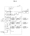
- FIG. 3 is a block diagram showing one embodiment of a numerical controller that constitutes a synchronous controller for performing the work shown in FIG. 2.
- a CPU 11 is a processor used for the overall control of the controller 10. Specifically, the CPU 11 reads, via a bus 19, a system program stored in a ROM 12, and controls the controller in accordance with the system program.
- a RAM 13 is stored with temporal data for calculation or display and various data that are input by an operator through a display/MDI unit 34.
- a CMOS memory 14 is backed up by a battery, not shown, and is hence constituted as a non-volatile memory capable of holding stored contents, even if the power to the numerical controller 10 is shut off.
- the CMOS memory 14 stores a machining program, etc. that are read through an interface 15 or that are input through the display/MDI unit 34.
- the interface 15 is used to connect external equipment 35 such as adapter with the controller 10.
- a machining program, etc. are read from the external equipment 35, through which a machining program edited in the controller 10 may be stored in an external storage means.
- a programmable controller (PC) 16 operates in accordance with a sequence program stored in the controller 10, and outputs signals to auxiliary equipment of a machine tool through an I/O unit 17, thus controlling the equipment.
- the PC 16 also receives signals from switches, etc. of an operation panel provided on a main body of the machine tool, performs required signal processing, and outputs the processed signals to the CPU 11.
- the display/MDI unit 34 is a manual data input device that is provided with a display, a keyboard, etc.
- An interface 18 receives commands and data from the keyboard of the display/MDI unit 34 and outputs the same to the CPU 11.
- Axis control means 20-22 receive motion command amounts for the respective axes from the CPU 11, and output commands to servo amplifiers 23-25, respectively. In response to the commands, the servo amplifiers 23-25 drive axis servomotors 30-32. These axis servomotors 30-32 having position/velocity detectors feed position/velocity feedback signals from their position/velocity detectors back to the axis control means 20-22 for position/velocity feedback control. In FIG. 3, illustration of position/velocity feedback is omitted.
- the X- and Y-axis servomotors 30, 31 drive the nozzle 3 in the X- and Y-axis directions, respectively, and the Z-axis servomotor 32 serves as a servomotor for driving a feed means for feeding a heating wire from the nozzle 3.
- the above-described arrangement is the same as the conventional numerical controller.
- the synchronous controller of this embodiment constituted by such numerical controller, comprises a synchronous control program that is stored in the ROM 12 and a machining program, stored in the CMOS memory 14, for affixing a heating wire to a carpet.
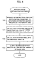
- FIG. 4 is a flowchart of processing that is executed for every interpolation period by the processor 11 of this embodiment.
- the processor 11 reads, as conventionally, one block of the machining program and executes a command that is read therefrom. If a motion command is read, processing for interpolation/distribution and processing for acceleration/deceleration (before or after the interpolation) are as conventionally performed, to determine amounts of motion X, Y to be distributed to the X- and Y-axes constituting the master axis (Step 100). Next, on the basis of the thus determined distribution motion amounts X, Y, calculation of the equation (1) is performed to determine, as amount of motion M of the master axis, an amount of composite motion of the nozzle 3 on the carpet plane (Step 101).
- an amount of command motion S for the Z axis serving as the slave axis is then determined by multiplying the amount of motion M of the master by a predetermined proportional coefficient k (Step 102).
- the proportional coefficient k varies depending on the means for feeding a heating wire 2, more specifically, depending on how much amount the heating wire 2 is fed according to an amount of rotation of the Z-axis servomotor for driving the wire feed means.
- the amount of command motion S of the Z axis which is required to feed the heating wire 2 in an amount corresponding to the amount of motion M of the master axis, is determined by multiplying the motion amount M by k.
- S k ⁇ M
- the thus determined amount of motion S of the slave axis is output to the axis control circuit 22 for drivingly controlling the Z-axis servomotor 32, and the amounts of motion X, Y of the X and Y axes determined at Step 100 are output to the axis control circuits 20, 21 for drivingly controlling the X- and Y-axis servomotors 30, 31, respectively, whereupon the processing in the present period is completed.
- the respective axis control circuits 20-22 individually carry out position/velocity loop processing on the basis of the amounts of command motion received and the position/velocity feedback signals that are supplied from the position/velocity detectors, not shown, respectively attached to the servomotors 30-32, to drive the servomotors 30-32 through the servo amplifiers 23-25, thus moving the nozzle in the X and Y directions and feeding the heating wire 2 to coincide with the amount (velocity) of motion of the nozzle, whereby the heating wire 2 is affixed to the carpet 1.
- the heating wire 2 is affixed while reciprocating the nozzle 3 on the carpet plane, as shown in FIG. 2, based on the machining program.
- the master axis consists of the nozzle 3 driven by the X and Y axes that are controlled by the controller 10.
- processing shown at Step 100 in FIG. 4 is executed to detect amounts of motion of the plurality of axes constituting the master axis by using detectors and to determine the amounts of motion for every predetermined cycle.
- processing in Steps 101, 102 is executed to determine an amount of motion S of the slave axis, which is then output to axis control means for driving the slave axis.
- mean that constitutes the master axis is comprised of a mechanism driven by two axes, i.e., the X and Y axes.
- the amount of motion of the master axis may be determined from a composite vector of motions of three perpendicular axes (X, Y and Z axes), and the slave axis may be driven accordingly.
- the slave axis is moved in synchronism with and in a predetermined proportional relation to the master axis.
- the slave axis may be moved as a predetermined function of motion of the master axis.
- the slave axis may be drivingly controlled by using a multiplying factor, determined as a given function, for the slave axis with respect to the master axis.
- the present invention makes it possible to simply and easily synchronize a motion of the slave axis for moving a slave element with a motion of the master axis for moving a master element to perform a composite motion of a plurality of axes. Even if the master axis serves as means for driving the master element by a composite motion of a plurality of axes of an external machine or apparatus, the slave axis can also be synchronously controlled with ease.
Landscapes
- Engineering & Computer Science (AREA)
- Computing Systems (AREA)
- Theoretical Computer Science (AREA)
- Human Computer Interaction (AREA)
- Manufacturing & Machinery (AREA)
- Physics & Mathematics (AREA)
- General Physics & Mathematics (AREA)
- Automation & Control Theory (AREA)
- Numerical Control (AREA)
- Control Of Position Or Direction (AREA)
Abstract
Description
Claims (2)
- A synchronous controller for driving a slave axis to synchronously follow a master axis performing a composite motion of a plurality of axes, comprising:a master-axis motion amount calculation section for calculating a motion command amount of the master axis by combining motion command amounts of the plurality of axes at every predetermined period; anda synchronous processing section for calculating a motion command amount of the slave axis at every predetermined period based on the motion command amount of the master axis calculated by said master-axis motion amount calculation section to be outputted for the slave axis.
- A synchronous controller for driving a slave axis to synchronously follow an operation of a master axis performing a composite motion of a plurality of axes, comprising:a master-axis motion amount calculation section for calculating a motion amount of the master axis by combining motion amounts detected by detectors of the plurality of axes for every predetermined period; anda synchronous processing section for calculating a motion amount of the slave axis at every predetermined period based on the motion amount of the master axis calculated by said master-axis motion amount calculation section to be outputted for the slave axis.
Applications Claiming Priority (2)
| Application Number | Priority Date | Filing Date | Title |
|---|---|---|---|
| JP2002367603 | 2002-12-19 | ||
| JP2002367603A JP2004199433A (en) | 2002-12-19 | 2002-12-19 | Synchronous control device |
Publications (2)
| Publication Number | Publication Date |
|---|---|
| EP1431852A2 true EP1431852A2 (en) | 2004-06-23 |
| EP1431852A3 EP1431852A3 (en) | 2004-12-22 |
Family
ID=32376285
Family Applications (1)
| Application Number | Title | Priority Date | Filing Date |
|---|---|---|---|
| EP03257828A Withdrawn EP1431852A3 (en) | 2002-12-19 | 2003-12-12 | Synchronous controller |
Country Status (3)
| Country | Link |
|---|---|
| US (1) | US6897626B2 (en) |
| EP (1) | EP1431852A3 (en) |
| JP (1) | JP2004199433A (en) |
Cited By (4)
| Publication number | Priority date | Publication date | Assignee | Title |
|---|---|---|---|---|
| EP1801680A2 (en) | 2005-12-20 | 2007-06-27 | KUKA Roboter GmbH | Process for moving a robot |
| EP1669828A3 (en) * | 2004-12-09 | 2008-04-30 | Fanuc Ltd | Synchronous controller |
| EP1956453A1 (en) * | 2007-02-05 | 2008-08-13 | Robert Bosch Gmbh | Method for operating machines with adjustable movement profiles |
| EP3091409A1 (en) * | 2015-04-28 | 2016-11-09 | Omron Corporation | Controller, control system, control method for controller, control program, and storage medium |
Families Citing this family (17)
| Publication number | Priority date | Publication date | Assignee | Title |
|---|---|---|---|---|
| JP2004246498A (en) * | 2003-02-12 | 2004-09-02 | Fanuc Ltd | Position control device |
| JP3830475B2 (en) * | 2003-08-05 | 2006-10-04 | ファナック株式会社 | Control device |
| EP1574921B1 (en) * | 2004-03-11 | 2012-12-12 | Omron Corporation | Synchronous controller |
| JP2005322076A (en) * | 2004-05-10 | 2005-11-17 | Fanuc Ltd | Numerical controller |
| JP4743649B2 (en) * | 2005-02-24 | 2011-08-10 | 株式会社リコー | Curved surface polishing apparatus and curved surface polishing method |
| WO2007057390A2 (en) * | 2005-11-16 | 2007-05-24 | Abb Ab | Method and device for controlling motion of an industrial robot with a position switch |
| JP5173522B2 (en) * | 2008-03-26 | 2013-04-03 | 三菱電機株式会社 | Electronic cam control device |
| US20130166059A1 (en) * | 2011-06-14 | 2013-06-27 | Mitsubishi Electric Corporation | Numerical control device |
| DE102015008188B3 (en) * | 2015-06-25 | 2016-06-16 | Kuka Roboter Gmbh | Departure of a predetermined path with a robot |
| JP2017102509A (en) * | 2015-11-30 | 2017-06-08 | ファナック株式会社 | Cam data display device |
| JP6441257B2 (en) * | 2016-04-28 | 2018-12-19 | ファナック株式会社 | Numerical control apparatus and synchronous tracking control method |
| EP3321754B1 (en) * | 2016-11-11 | 2020-09-09 | Siemens Aktiengesellschaft | Method for optimizing of movement profiles, computer program product, control device and installation or robot |
| EP3561621B1 (en) | 2018-04-26 | 2023-01-04 | Siemens Aktiengesellschaft | Determination of an adapted leading value |
| JP7310465B2 (en) * | 2018-12-27 | 2023-07-19 | オムロン株式会社 | Synchronous control device, synchronous control system, synchronous control method, and simulation device |
| JP6943268B2 (en) * | 2019-03-29 | 2021-09-29 | オムロン株式会社 | Control device |
| US12510882B2 (en) | 2020-06-24 | 2025-12-30 | Siemens Aktiengesellschaft | Method for controlling a plurality of execution mechanisms, electronic device, and storage medium |
| CN113910234B (en) * | 2021-10-27 | 2022-10-14 | 因格(苏州)智能技术有限公司 | Double-manipulator control method and storage medium |
Family Cites Families (12)
| Publication number | Priority date | Publication date | Assignee | Title |
|---|---|---|---|---|
| US3593615A (en) * | 1969-11-12 | 1971-07-20 | Ralph W Krutsinger Jr | Mechanism for transferring dimensional and shape information between two and three dimensional objects |
| JPS5717012A (en) * | 1980-07-07 | 1982-01-28 | Fanuc Ltd | Numerical controller |
| CA1201321A (en) | 1981-12-22 | 1986-03-04 | Anne-Marie Dahlen | Protein-fruit drink |
| GB2142257B (en) * | 1983-07-02 | 1986-11-26 | Gen Motors Overseas | Adhesive application apparatus |
| US4739344A (en) * | 1987-02-27 | 1988-04-19 | Astro-Med, Inc. | Chart recorded having multiple thermal print heads |
| JPH07107643B2 (en) * | 1988-02-22 | 1995-11-15 | 本田技研工業株式会社 | NC synchronous control system |
| US5121329A (en) * | 1989-10-30 | 1992-06-09 | Stratasys, Inc. | Apparatus and method for creating three-dimensional objects |
| JP2880590B2 (en) * | 1991-07-24 | 1999-04-12 | 株式会社不二越 | Synchronous control method for industrial robot |
| DE19538826A1 (en) * | 1995-10-18 | 1997-04-30 | Siemens Ag | Axis synchronisation system for numerical machine tool control or robot |
| JP2000271888A (en) | 1999-03-25 | 2000-10-03 | Fanuc Ltd | Robot controller |
| EP1090722B1 (en) * | 1999-09-16 | 2007-07-25 | Fanuc Ltd | Control system for synchronously cooperative operation of a plurality of robots |
| JP3504222B2 (en) * | 2000-09-04 | 2004-03-08 | ファナック株式会社 | Robot controller |
-
2002
- 2002-12-19 JP JP2002367603A patent/JP2004199433A/en active Pending
-
2003
- 2003-12-12 EP EP03257828A patent/EP1431852A3/en not_active Withdrawn
- 2003-12-16 US US10/735,705 patent/US6897626B2/en not_active Expired - Fee Related
Cited By (7)
| Publication number | Priority date | Publication date | Assignee | Title |
|---|---|---|---|---|
| EP1669828A3 (en) * | 2004-12-09 | 2008-04-30 | Fanuc Ltd | Synchronous controller |
| US7859214B2 (en) | 2004-12-09 | 2010-12-28 | Fanuc Ltd. | Synchronous controller |
| EP1801680A2 (en) | 2005-12-20 | 2007-06-27 | KUKA Roboter GmbH | Process for moving a robot |
| EP1801680A3 (en) * | 2005-12-20 | 2009-09-02 | KUKA Roboter GmbH | Process for moving a robot |
| EP2574998A1 (en) * | 2005-12-20 | 2013-04-03 | KUKA Laboratories GmbH | Process for moving a robot |
| EP1956453A1 (en) * | 2007-02-05 | 2008-08-13 | Robert Bosch Gmbh | Method for operating machines with adjustable movement profiles |
| EP3091409A1 (en) * | 2015-04-28 | 2016-11-09 | Omron Corporation | Controller, control system, control method for controller, control program, and storage medium |
Also Published As
| Publication number | Publication date |
|---|---|
| US6897626B2 (en) | 2005-05-24 |
| EP1431852A3 (en) | 2004-12-22 |
| US20040128022A1 (en) | 2004-07-01 |
| JP2004199433A (en) | 2004-07-15 |
Similar Documents
| Publication | Publication Date | Title |
|---|---|---|
| US6897626B2 (en) | Synchronous controller | |
| US8483865B2 (en) | Numerical controller with tool trajectory display function | |
| EP1353251A2 (en) | Numerical controller | |
| JPH09323279A (en) | Integrated control system for work robot | |
| EP1447728A2 (en) | Position control device | |
| US20080120566A1 (en) | Device for displaying a moving locus | |
| JP2021056835A (en) | Simulation device | |
| EP0397887B1 (en) | Method of correcting machining program | |
| EP0510204A1 (en) | Method of evaluating operating accuracy in numerically controlled machine | |
| US7203568B2 (en) | Numerical controller | |
| US6546127B1 (en) | System and method for real time three-dimensional model display in machine tool | |
| US20070185609A1 (en) | Numerical control method | |
| US5181178A (en) | Spindle control command method | |
| EP0851328B1 (en) | Superposition control method using numerical controller | |
| KR910002317B1 (en) | Numerical control device | |
| US6999844B2 (en) | Numerical controller | |
| WO1991010179A1 (en) | Display system of numerical controller | |
| EP0428950A2 (en) | Motor driving control apparatus | |
| EP0107794B1 (en) | Numerical control system | |
| US6397123B1 (en) | Numerical control apparatus | |
| US7370796B2 (en) | Laser processing system | |
| EP1327924A1 (en) | Numerical control method and numerical control device | |
| US6150786A (en) | Controller for industrial machine | |
| JP2003044144A (en) | Multi-axis synchronous control device, multi-axis synchronous control method, and multi-axis synchronous control program | |
| US5583409A (en) | Numerical control apparatus and method for controlling a machine |
Legal Events
| Date | Code | Title | Description |
|---|---|---|---|
| PUAI | Public reference made under article 153(3) epc to a published international application that has entered the european phase |
Free format text: ORIGINAL CODE: 0009012 |
|
| AK | Designated contracting states |
Kind code of ref document: A2 Designated state(s): AT BE BG CH CY CZ DE DK EE ES FI FR GB GR HU IE IT LI LU MC NL PT RO SE SI SK TR |
|
| AX | Request for extension of the european patent |
Extension state: AL LT LV MK |
|
| PUAL | Search report despatched |
Free format text: ORIGINAL CODE: 0009013 |
|
| AK | Designated contracting states |
Kind code of ref document: A3 Designated state(s): AT BE BG CH CY CZ DE DK EE ES FI FR GB GR HU IE IT LI LU MC NL PT RO SE SI SK TR |
|
| AX | Request for extension of the european patent |
Extension state: AL LT LV MK |
|
| 17P | Request for examination filed |
Effective date: 20050413 |
|
| AKX | Designation fees paid |
Designated state(s): DE |
|
| STAA | Information on the status of an ep patent application or granted ep patent |
Free format text: STATUS: THE APPLICATION IS DEEMED TO BE WITHDRAWN |
|
| 18D | Application deemed to be withdrawn |
Effective date: 20060706 |